Connecting Device for the Fluidic Connection of a Fluid Pipe Section to a Further Fluid Pipe Section
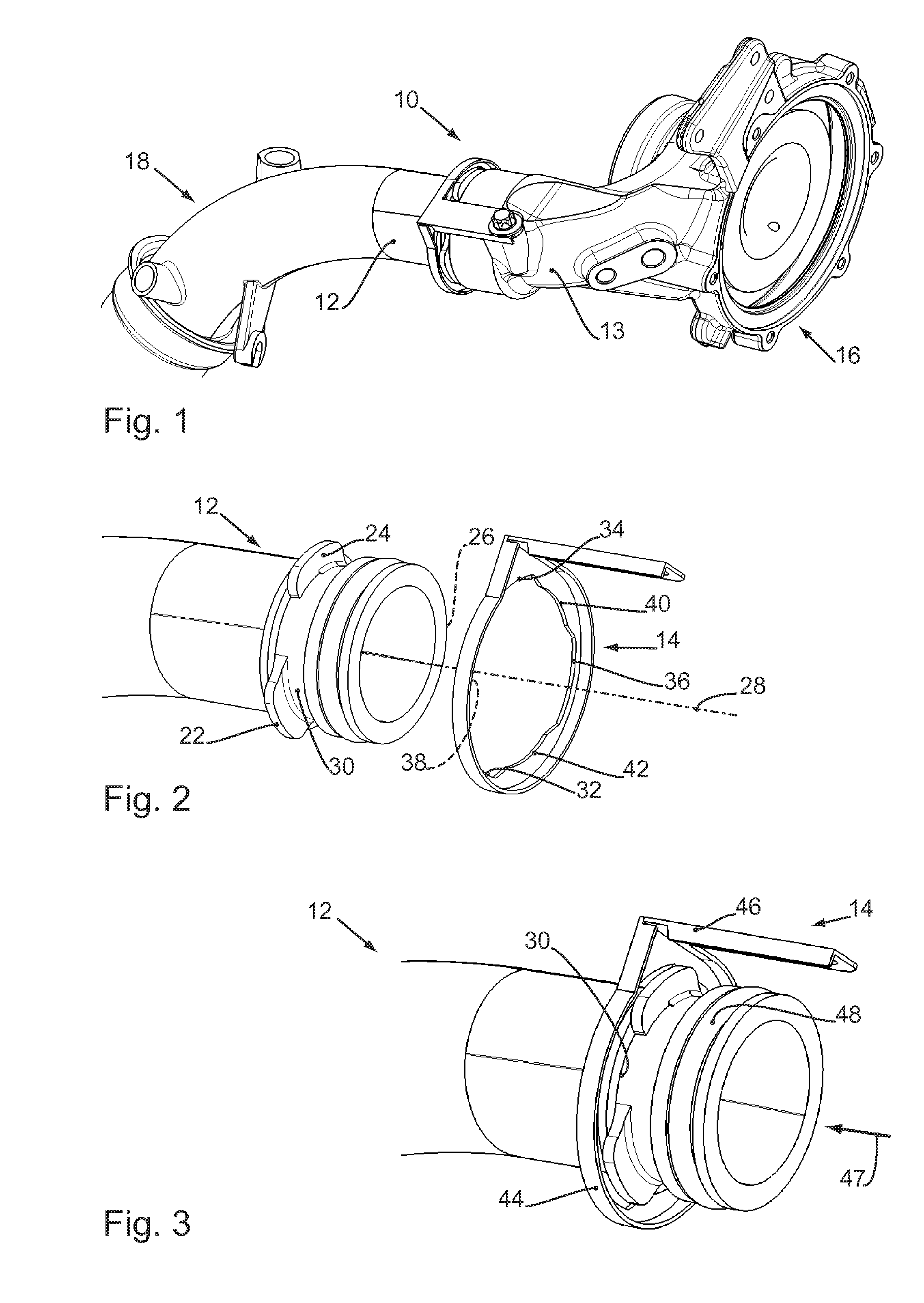
The invention relates to a connecting device for the fluidic connection of a fluid pipe section to a further fluid pipe section, in particular of a turbocharger having a charge air pipe. From the prior art, it is known to fluidically connect a turbocharger to a further device, for example to a resonator, by means of a charge air pipe. Such a charge air pipe is also referred to as a charge air hose. US 2012/0298063 A1 discloses a connecting device for connecting a charge air pipe to a turbocharger. Here, the connecting device has a bayonet connection. Furthermore, a connecting device for connecting a charge air pipe to a turbocharger which has a sealing ring has been disclosed in US 2007/0216161 A1. Finally, connecting devices in the form of “screw solutions” which have a strap, wherein the strap connects two pipe end sections and is fixed to a pipe end section by means of a screw in each case, are used on the market. The known connecting devices must either be produced laboriously and expensively or, ultimately, can only be fitted in a circuitous manner due to the restricted installation conditions in the engine compartment of a motor vehicle. At the same time, the costs for manufacturing such a connecting device are critical, mainly because the connecting devices in question are mass-produced products. The invention is based on the object of providing a connecting device for the fluidic connection of a fluid pipe section to a further fluid pipe section, for an example, a fluidic connection of a turbocharger to a charge air pipe in such a way that the connection can be produced cost effectively and is also easy and convenient to fit. This object is achieved by a connecting device with the characteristics of Claim 1. The dependent claims specify expedient developments. The connecting device according to the invention for the fluidic connection of a fluid pipe section to a further fluid pipe section, in particular for the connection of a turbocharger to a charge air pipe, comprises a first pipe end section and a second pipe end section, wherein a retaining element of the connecting device, which can be rotated at least to a limited extent about the longitudinal axis of the first pipe end section, is arranged on the first pipe end section, wherein the retaining element and the first pipe end section have a plurality of projections which form a bayonet connection between the first pipe end section and the retaining element, wherein the retaining element has a strap with a through-opening into which a screw of the retaining element is fed, and wherein the second pipe element has an opening into which the screw can be inserted. The connecting device therefore has two pipe end sections which can be connected to one another. A first pipe end section has a retaining element which can be rotated at least to a limited extent about the longitudinal axis of the first pipe end section. The retaining element has a strap which is provided with a through-opening. A screw is fed into the through-opening. The screw therefore extends through the through-opening of the strap of the retaining element and can be inserted, i.e. screwed, into an opening of the second pipe end section. For this purpose, the opening of the second pipe end section can be provided with a female thread which corresponds to a male thread of the screw. A bayonet connection is formed between the retaining element and the first pipe end section by means of a plurality of projections. The bayonet connection limits at least the possibility of movement of the retaining element in the direction of the pipe end of the first pipe end section in the connected state of the connecting device. The connection of the two pipe end sections therefore takes place from the first pipe end section via the bayonet connection to the retaining element with the strap and further to the screw which is inserted into the second pipe end section. The connecting device has a simple design structure and can therefore be produced cost-effectively. Furthermore, it can be easily fitted in a restricted engine compartment. The retaining element only has to be placed onto the first pipe end section and subsequently rotated relative to the first pipe end section about its longitudinal axis in order to bring the bayonet connection into its locking position and, by this means, to couple the retaining element tightly to the first pipe end section. It is therefore not necessary to rotate the whole pipe end section in order to close the bayonet connection. The connecting device is finally fixed by screwing the single screw into the opening of the second pipe end section. As a result, the two pipe end sections are connected tightly and in a fixed rotational relationship to one another. This saves a screw compared with known “screw solutions” and the overall assembly is simplified. The connection is formed particularly stably when the projections of the retaining element which constitute a part of the bayonet connection are designed as one part, i.e. in one piece, with the further components of the retaining element. Alternatively or in addition, for stable formation of the connection, the projections of the first pipe end section are preferably designed as one part with the further components of the pipe end section. The pipe end sections can preferably be slid inside one another. For example, the first pipe end section can be fed axially into the second pipe end section. Alternatively, the second pipe end section can be fed into the first pipe end section. This enables a particularly fluid-tight connection to be achieved. In order to further simplify the handling of the connecting device for a fitter, the first pipe end section can have at least one stop which limits the rotation of the retaining element about the first pipe end section. As a result of this, the fitter only has to turn the retaining element “as far as the stop” in order to ensure the correct closure of the bayonet connection. According to the invention, the strap can have a guide section for locating the correct assembly position of the strap on the second pipe end section. In doing so, the guide section can be designed as an angled edge section of the strap which interacts with a guide surface of the second pipe end section. The retaining element can have a fixing section for mounting the retaining element on the first pipe end section which encompasses more than half the circumference of the first pipe end section. The retaining element can therefore be designed in the form of a clamp which can be pressed onto the first pipe end section. In order to achieve a particularly secure connection, the fixing section is preferably substantially ring-shaped, wherein the fixing section fully encompasses the circumference of the first pipe end section. The strap constitutes a particularly heavily stressed part of the connecting device according to the invention. A design of the connecting device which is at the same time strong and cost-effective is enabled in that the strap is made of sheet metal. The stability of the connecting device is particularly high when the strap is formed as one part with the fixing section. In particular, the retaining element can be made of metal or a fiber composite material. An elastic sealing element can be arranged or formed between the first pipe end section and the second pipe end section in order to achieve a particularly airtight connection of the pipe end sections. In particular, the elastic sealing element can be a radial sealing element. The elastic sealing element can be formed as one part with the connecting device. On the other hand, the sealing element can also be designed in the form of a sealing ring so that a standardized sealing element which can be purchased inexpensively is used. In an embodiment of the connecting device according to the invention for the fluidic connection of a turbocharger to a charge air pipe, the first pipe end section can be a pipe end section of the turbocharger and the second pipe end section a pipe end section of the charge air pipe. At the same time, the first pipe end section can be formed as one part with a turbocharger housing. Alternatively, in the embodiment of the connecting device according to the invention for the fluidic connection of a turbocharger to a charge air pipe, the first pipe end section can be a pipe end section of the charge air pipe and the second pipe end section a pipe end section of the turbocharger. At the same time, the second pipe end section can be formed as one part with a turbocharger housing. The connecting device according to the invention can be used for connecting pipes for channeling air. Furthermore, the connecting device can be designed for connecting pipes for channeling other media. Further characteristics and advantages of the invention can be seen from the following detailed description of an exemplary embodiment of the invention based on the figures, the drawing, which shows the details essential to the invention, and from the claims. The characteristics shown in the drawing are presented in such a way that the special features according to the invention can be made clearly visible. The different characteristics can be realized individually in their own right or jointly in any combination in variants of the invention. The drawing shows the assembly of a connecting device according to the invention in single steps ( In detail: When the retaining element 14 slides onto the first pipe section 12, the projections 22, 24, 26 of the first pipe end section 12 can be guided by matching recesses 32, 34, 36. More accurately, the projection 22 can be guided by or be slide through the recess 32, the projection 24 by or through the recess 34 and the projection 26 by or through the recess 36. The retaining element 14 has three radially inwardly extending projections 38, 40, 42 which, in the connected state of the connecting device 10 (see In order to form a particularly well sealed connection, the first pipe end section 12 has an elastic sealing element 48, which is not shown in the subsequent figures for reasons of clarity. The through-opening 54 is designed in the form of an elongated hole to enable play of the first pipe end section 12 along its longitudinal axis 28 (see The strap 46 has a guide section 60 for resting against the second pipe end section 13. The guide section 60 runs substantially parallel to the longitudinal axis 28 (see In summary, the invention relates to a connecting device for connecting two pipe end sections in a fluidically sealed manner. The connecting device has a retaining element which can be fitted by means of a bayonet connection to a first pipe end section. The retaining element has strap which can be fixed to a second pipe end section by means of a screw of the connecting device. The connecting device is therefore particularly simple from a constructive point of view, creates a sealed connection, and can also be fitted in restricted conditions. The invention relates to a connecting device (10) for connecting two pipe end sections (12, 13) in a fluidically sealed manner. The connecting device (10) has retaining element which can be fitted to a first pipe end section (12) by means of a bayonet connection. The retaining element has a strap (46) which can be fixed to a second pipe end section (13) by means of a screw (58) of the connecting device (10). The connecting device (10) is therefore particularly simple from a constructive point of view, creates a sealed connection, and can also be easily fitted in restricted condition. 1. A connecting device for the fluidic connection of a fluid pipe section to a further fluid pipe section, comprising:
the first fluid pipe section having a first pipe end section; and the further fluid pipe section having a second pipe end section; a connecting device for fluidically connecting and securing together the first pipe end section to the second pipe end section, the connecting device including:
a retaining element axially inserted onto and axially removable from the first pipe end section; wherein the retaining element is configured and adapted to be rotated at least to a limited extent about a longitudinal axis of the first pipe end section; wherein the retaining element is arranged on the first pipe end section; a plurality of radially outwardly extending projections arranged on an outer circumference of the first pipe end section, the plurality of radially outwardly extending projections engaging with the retaining element to form a rotationally engagable axial position locking connection between the retaining element and the first pipe end section; wherein the retaining element has a strap with a through-opening into which a screw of the retaining element is inserted; and wherein the second pipe end section has an screw receiving opening into which the screw can be inserted to axially connect and axially positionally lock the fluid pipe section to the further fluid pipe section. 2. The connecting device as claimed in the first pipe end section has at least one stop which limits the rotation of the retaining element about the first pipe end section. 3. The connecting device as claimed in the retaining element has a fixing section which encompasses more than half of an outer circumference of the first pipe end section, the fixing section configured ad adapted to rotatably engage and mount the retaining element onto the first pipe end section. 4. The connecting device as claimed in the fixing section is substantially ring-shaped and fully encompasses the circumference of the first pipe end section. 5. The connecting device as claimed in the strap is made of sheet metal. 6. The connecting device as claimed in the strap is formed unitarily with and in one piece with the fixing section of the retaining element. 7. The connecting device as claimed in an elastic sealing element is arranged or formed between and sealing between the first pipe end section and the second pipe end section, the elastic sealing element fluidically sealing the connection between the first pipe end section and the second pipe end section. 8. The connecting device as claimed in the first pipe end section is a charge air pipe; and the second pipe section is an internal combustion engine turbocharger. 9. The connecting device as claimed in the second pipe end section is a charge air pipe; and the first pipe section is an internal combustion engine turbocharger. 10. The connecting device as claimed in the strap is made of sheet metal and formed unitarily with and in one piece with the fixing section of the retaining element; and wherein an elastic sealing element is arranged or formed between and sealing between the first pipe end section and the second pipe end section, the elastic sealing element fluidically sealing the connection between the first pipe end section and the second pipe end section. 11. A charge air pipe having a connecting device according to the first fluid pipe section is a first charge air pipe end section for a turbocharger; and the second fluid pipe section is a first charge air pipe end section for a turbocharger.TECHNICAL FIELD
BACKGROUND
SUMMARY OF THE INVENTION
BRIEF DESCRIPTION OF THE DRAWINGS
DETAILED DESCRIPTION OF THE INVENTION