SALAD SPINNER BRAKE MECHANISM
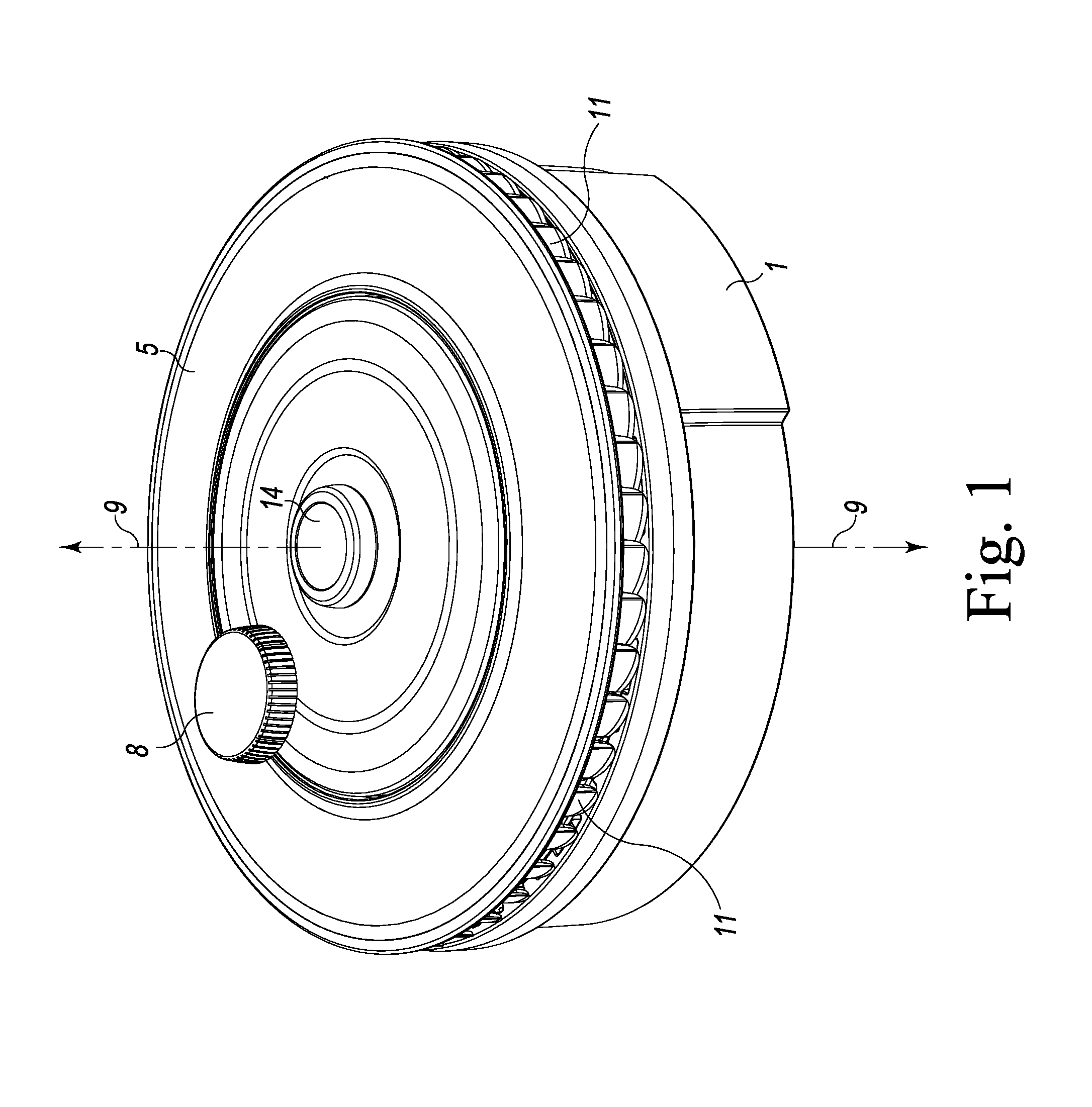
This is a continuation-in-part of U.S. patent application Ser. No. 13/898,227 filed on May 20, 2013, which was a continuation-in-part of U.S. patent application Ser. No. 12/753,300 filed on Apr. 2, 2010, now abandoned, which was a non-provisional application based on U.S. Provisional Patent Application Ser. No. 61/211,653 filed on Apr. 2. 2009. The present invention relates to an improved food preparation product. More particularly, it is a rotatable greens drying device (hereinafter, salad spinner) that decreases the time and effort required to dry washed greens by use of an improved brake mechanism. Salad spinner devices are common and not new to the marketplace. All known salad spinners are designed to create centrifugal force that expedites removal of residual water which accumulates after rinsing leafy vegetables. This is done to avoid soggy greens which can detract from the texture and quality of a salad. Each known device in the prior art employs a mechanical method for swiftly rotating a perforated container filled with rinsed greens inside a vessel that captures and contains water after its removal. This mechanical method is not the subject of this disclosure as it could be satisfactorily achieved by using one of several drive mechanisms already known in the public domain. Most salad spinner devices consist of five main components: (1) a rigid and stationary exterior main bowl with (2) an exterior lid, (3) an interior rotatable colander with (4) an engageable interior lid, and (5) a rotary drive device that is fastened to the exterior lid which when activated by the user, spins the interior lid and colander in unison. The exterior lid, rotary drive, and interior lid are usually combined in a lid assembly. The user typically will fill the colander with leafy greens and wash them thoroughly under a faucet. Then, the dripping colander is placed inside the main bowl on a countertop, the lid assembly (containing the exterior lid, interior lid and the rotary device) is placed on top of the bowl and the user activates the rotary drive device to create the centrifugal force needed to remove water from the greens. The colander rotation has to stop before the dewatered greens can be removed. A brake is an additional component that is sometimes found on salad spinners. The colander, its contents, and the interior lid represent a considerable mass that, when rotating together in a low-friction environment, take a long time to slow back down to stationary when application of spinning force is ceased. Simpler devices without a brake require the user to either (1) simply wait for the rotation to decay or (2) remove the lid and stop the fast-spinning colander by hand. The former method adds considerable time to the operation, while the latter technique is awkward and messy. One type of brake known since at least French Patent 743,906, issued Jan. 16, 1933, uses a simple exterior lid-mounted elastic button 21 to selectively contact a point on the interior lid located off-axis, that is, radially-outward of the center. A latter example of the simple radially-displaced elastic brake is shown in U.S. Pat. No. 6,018,883 to Mulhauser. The rotating mechanism occupies the center of both devices, and apparently no thought was given to coaxially mounting the brake with the rotating mechanism. One major drawback of an off-axis, radially-displaced brake is that substantial unbalancing moment is applied to the spinning mass, making the braking action rough, loud, hard to control, and a generally unpleasant end to an otherwise elegant operation. Another drawback of the radially-displaced type of brake is that the support system for the rotating mass must be heavier to provide resistance to the unbalancing moment of the brake. There is a need, then, for a salad spinner device that provides a smooth and balanced braking action applied coaxially with the colander axis of rotation. The salad spinner of the present invention includes a brake that is coaxially applied with the colander axis of rotation. A more complete understanding of the invention and its advantages will be apparent from a review of the Detailed Description in conjunction with the following Drawings, in which: Referring initially to In operation, to begin use, the support frame 1 and colander 3 are first extended to their use configurations. Leafy greens are placed inside the colander 3, washed with water and spread evenly. The removable drive assembly 5, with attached fan 7 and actuator 8, is removably coupled to the support frame 1 and colander 3 by placing it on top of the support frame 1 directly above the colander 3. The removable drive assembly 5 self-locates with the fan 7 affixed to the colander rim 3 Further details regarding the salad spinner construction and operation are found in U.S. patent application Ser. No. 13/898,227 filed on May 20, 2013, and U.S. patent application Ser. No. 12/753,300 filed on Apr. 2, 2010, and the disclosures of each are included by reference thereto as if fully set forth herein. As best shown in In general, drive assembly 5 includes the actuator 8 connected to a drive plate 15. Drive plate 15 is connected via a ring gear (shown in Describing now the drive assembly 5 and its coaxial brake in more detail, the salad spinner includes the drive assembly 5 removably coupled to a colander 3. The actuator 8 transmits a driving input applied to the actuator 8 to rotate the colander 3 about an axis of rotation 9. The actuator 8 is rotatably mounted to a drive plate 15 a radial distance from the axis of rotation 9 such that the drive plate 15 and actuator 8 are a crank mechanism for imparting rotary force around axis of rotation 9. A transmission for rotating force provided by the crank includes a ring gear on the drive plate 15 (shown in A one-way, freewheel clutch is also provided. The clutch includes the clutch member 18, which has arms 33 below driven gear 17 loosely constraining the plurality of clutch cylinders 20. Hub 19 has an internal clutch surface 35 for frictional engagement with the clutch member 18 by way of the clutch cylinders 20 and the arms 33 when the drive plate 15 is rotated in one direction and for freewheeling disengagement when the drive plate rotation speed is less than the rotation speed of the hub. The hub 19 is adapted and arranged to be connected in a rotary driving relationship to the colander 3 for rotation. In the preferred embodiment, the hub and colander connection includes a pair of diametrically opposed dogs 21 pivotally connected to the hub 19. The dogs 21 engage a pair of corresponding fan slots 37 on fan 7. Fan 7 has an outer rim 39 frictionally engaged with the outer rim 3 The coaxial brake selectively applies braking force to the hub 19 coaxially with the colander axis of rotation 9, which is the essential feature of this invention. The coaxial brake includes button 14 fixed to the drive plate 15. Button 14 is constrained for linear motion with respect to the drive plate 15 by a plurality of semi-cylindrical button fingers 43 extending vertically-downward from an internal bottom surface 45 of the button 14. Button fingers 43 extend through loosely-fitted, cooperating, semi-cylindrical finger holes 47 in the drive plate 15, such that linear motion is permitted but corotation of the button 14 and drive plate 15 is provided. Button 14 outward linear motion is constrained by engagement tabs 49 extending inwardly from an internal side surface 51 of the button 14. The engagement tabs 49 cooperate with engagement slots 53 on the drive plate 15 to establish a limit on outward linear motion of the button 14. Coil spring 22 is retained by the button 14 and drive plate 15 and is adapted and arranged to urge the button 14 outwardly away from the drive plate 15. The brake actuation element 23 has an upper ring 55, two semi-cylindrical actuation arms 57 depending from the upper ring 55, and a brake surface 59 at the bottom 61 of each actuation arm 57. The actuation arms 57 extend vertically-downward from the upper ring 55 through loosely-fitted, cooperating, semi-cylindrical arm holes 63 in the drive assembly top 31. The upper ring 55 is closely-adjacent to bottoms 65 of the button fingers 43 to receive coaxial, linear force from linear motion applied to the button 14. Drive assembly top 31 remains stationary in all phases of operation of the salad spinner, so brake actuation element 23 does not rotate but is allowed linear relative motion with respect to the drive assembly top 31. Brake ring 24 is located closely-adjacent to the brake surfaces 59 at the bottoms 61 of the actuation arms 57. Brake ring 24 is a resilient, toroidal ring with a top surface 67 adjacent to the bottoms 61 of the actuation arms 57. Top surface 67 receives coaxial, linear force transmitted by the brake actuation element 23 from the button 14. Brake ring 24 also has a bottom surface 69. A braked surface 71 is formed on the hub and located closely-adjacent to the brake ring bottom surface 69. The braked surface 71 is located within the hub 19 to receive coaxial, linear force applied by the brake ring bottom surface 69. The coaxial, linear force is transmitted to the hub by the brake ring 24, brake actuation element 23, and button 14. Referring now to In In Though it is intended to fully describe the invention as set forth here, it is reasonable to assume that one skilled in the art could adjust, modify, subtract or adapt certain aspects of this salad spinner device without departing from its original scope. The implementation of individual or combined improvements disclosed here as part of another salad spinner device would be possible. For example, one variation would be to omit the collapsibility of the colander and employ a rigid version. Still another example would be to support or suspend this salad spinner device by another method such as with folding legs or a rigid outer bowl. The colander itself could, in fact, be freestanding—its lower end engaging with an electronic or manual drive component placed on the floor of a sink. Various known drive mechanisms could include pull-chord escapements, levers, gear sets, plungers, and electric motors. Again, these mechanisms are not the subject matter of this disclosure. The gist of this improved salad spinner is that a coaxial brake is employed. The recommended materials will likely be, but are not limited to rigid and elastomeric plastic or metal. While the invention has been illustrated and described as embodied in a preferred salad spinners, it is not intended to be limited to the details shown, since it will be understood that various omissions, modifications, substitutions and changes in the forms and details of the devices illustrated in their operation can be made by those skilled in the art without departing in any way from the spirit of the present invention. Without further analysis, the foregoing will so fully reveal the gist of the present invention that others can, by applying current knowledge, readily adapt it for various applications without omitting features that, from the standpoint of prior art, fairly constitute essential characteristics of the generic or specific aspects of this invention. A salad spinner has a hub connected in a rotary driving relationship to a colander mounted within the salad spinner for rotation about an axis of rotation. A brake provides braking force to the hub coaxially with the colander axis of rotation. 1. A salad spinner comprising:
a hub adapted and arranged to be connected in a rotary driving relationship to a colander mounted within the salad spinner for rotation about an axis of rotation; and a brake adapted and arranged to provide braking force to the hub coaxially with the colander axis of rotation. 2. The salad spinner of 3. The salad spinner of 4. The salad spinner of 5. The salad spinner of 6. The salad spinner of 7. A salad spinner comprising:
a removable drive assembly removably coupled to a colander and including an actuator to transmit a driving input applied to the actuator to rotate the colander about an axis of rotation; the actuator being rotatably mounted to a drive plate a radial distance from the axis of rotation such that the drive plate and actuator are a crank mechanism for imparting rotary force around the axis of rotation; the drive plate connected to a hub adapted and arranged to be connected in a rotary driving relationship to the colander for rotation; a coaxial brake for selectively applying braking force to the hub coaxially with the colander axis of rotation; the coaxial brake including a button fixed to the drive plate and constrained for linear motion with respect thereto; a coil spring retained by the button and drive plate adapted and arranged to urge the button outwardly away from the drive plate; a brake actuation element to receive coaxial, linear force from linear motion applied to the button; a brake ring located closely-adjacent to the brake actuation element to receive coaxial, linear force transmitted by the brake actuation element from the button; and a braked surface formed on the hub located closely-adjacent to the brake ring, the braked surface being within the hub to receive coaxial, linear force applied by the brake ring, the coaxial, linear force transmitted to the hub by the brake ring, brake actuation element, and button. 8. The salad spinner of 9. The salad spinner of 10. The salad spinner of 11. The salad spinner of 12. The salad spinner of 13. The salad spinner of 14. The salad spinner of 15. The salad spinner of 16. A salad spinner comprising:
a removable drive assembly removably coupled to a colander and including an actuator to transmit a driving input applied to the actuator to rotate the colander about an axis of rotation; the actuator being rotatably mounted to a drive plate a radial distance from the axis of rotation such that the drive plate and actuator are a crank mechanism for imparting rotary force around the axis of rotation; a transmission including a ring gear on the drive plate, a pair of idler gears engaged with each other, with one idler gear engaged with the ring gear, the idler gears being rotatably mounted to a drive assembly top, and a driven gear fixed to a clutch member and engaged with the other idler gear; a one-way, freewheel clutch including the clutch member, the clutch member having arms below the driven gear loosely constraining a plurality of clutch cylinders, and a hub with an internal clutch surface for frictional engagement with the clutch member by way of the clutch cylinders and the arms when the drive plate is rotated in one direction, and for freewheeling disengagement when the drive plate rotation speed is less than the rotation speed of the hub; the hub adapted and arranged to be connected in a rotary driving relationship to the colander for rotation, the hub and colander connection including a pair of diametrically opposed dogs pivotally connected to the hub, the dogs engaging a pair of corresponding fan slots on a fan, and the fan having an outer rim frictionally engaged with an outer rim of the colander; a coaxial brake for selectively applying braking force to the hub coaxially with the colander axis of rotation; the coaxial brake including a button fixed to the drive plate and constrained for linear motion with respect thereto; the button being constrained for linear motion with respect to the drive plate by a plurality of semi-cylindrical button fingers extending vertically-downward from an internal bottom surface of the button through loosely-fitted, cooperating, semi-cylindrical finger holes in the drive plate, such that linear motion is permitted but corotation of the button and drive plate is provided; the button outward linear motion being constrained by engagement tabs extending inwardly from an internal side surface of the button, the engagement tabs cooperating with engagement slots on the drive plate to establish a limit on outward linear motion of the button; a coil spring retained by the button and drive plate adapted and arranged to urge the button outwardly away from the drive plate; a brake actuation element having an upper ring, two semi-cylindrical actuation arms depending from the upper ring, and a brake surface at the bottom of each actuation arm, the actuation arms extending vertically-downward from the upper ring through loosely-fitted, cooperating, semi-cylindrical arm holes in the drive assembly top, the upper ring being closely-adjacent to bottoms of the button fingers to receive coaxial, linear force from linear motion applied to the button; a brake ring located closely-adjacent to the brake surfaces at the bottoms of the actuation arms, the brake ring being a resilient, toroidal ring with a top surface adjacent to the bottoms of the actuation arms to receive coaxial, linear force transmitted by the brake actuation element from the button, and the brake ring having a bottom surface; and a braked surface formed on the hub located closely-adjacent to the brake ring bottom surface, the braked surface being within the hub to receive coaxial, linear force applied by the brake ring bottom surface, the coaxial, linear force transmitted to the hub by the brake ring, brake actuation element, and button.CROSS-REFERENCE TO RELATED APPLICATIONS
TECHNICAL FIELD
BACKGROUND OF THE INVENTION
SUMMARY OF THE INVENTION
BRIEF DESCRIPTION OF THE DRAWINGS
DETAILED DESCRIPTION