Wheel Bearing Apparatus
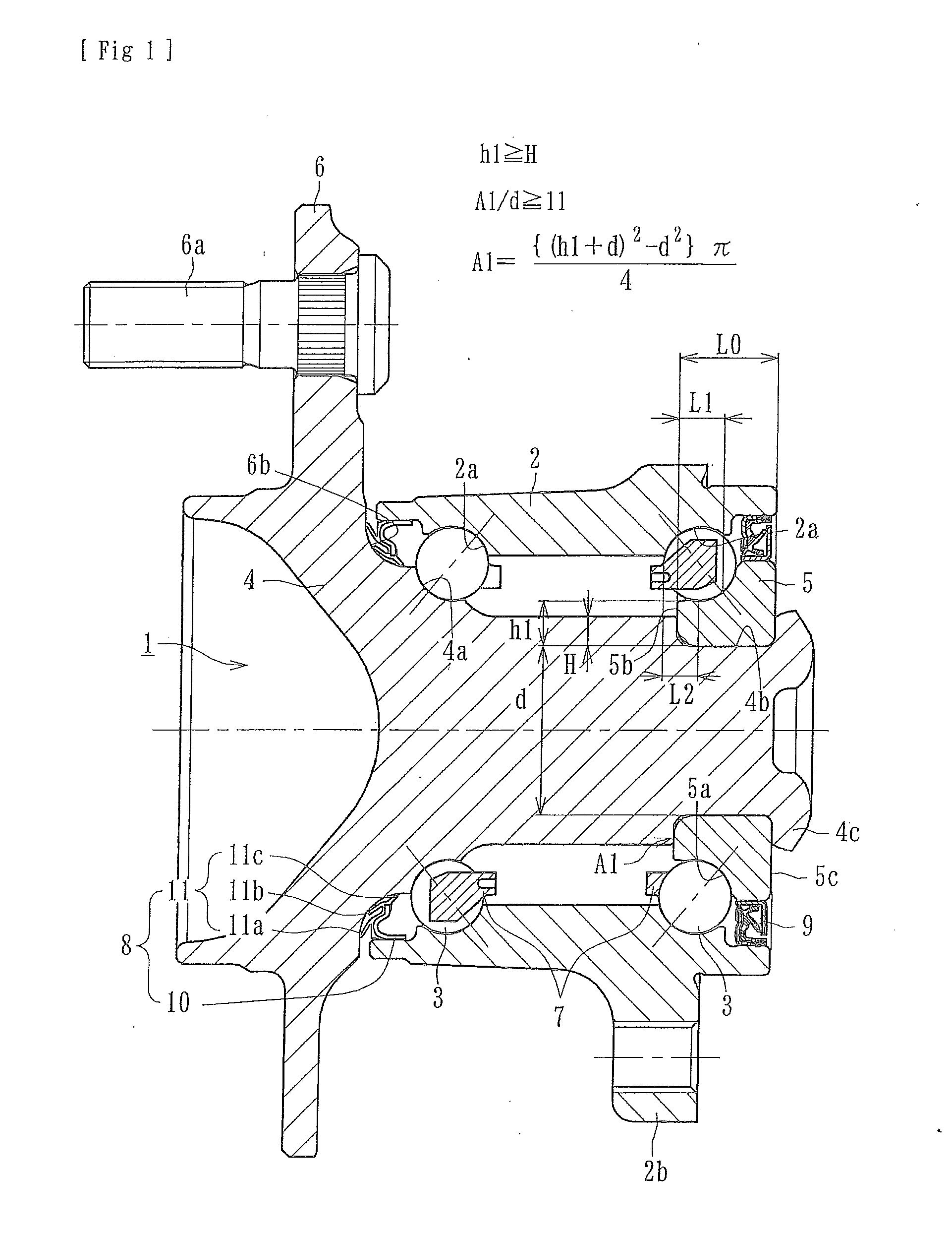
This application is a continuation of International Application No. PCT/JP2014/050144, filed Jan. 8, 2014, which claims priority to Japanese Application No. 2013-001666, filed Jan. 9, 2013. The disclosures of the above applications are incorporating herein by reference. The present disclosure generally relates to a wheel bearing apparatus that rotationally supports a wheel of a vehicle and, more particularly, to a wheel bearing apparatus with a self-retaining structure where an inner ring is secured on a wheel hub by swing caulking of the wheel hub. This is intended to suppress the hoop stress on the inner ring by the caulking process and to reduce bearing friction. There are two types of vehicle wheel bearing apparatus for automobiles, those used for driving wheels and those for driven wheels. In wheel bearing apparatus that rotationally supports wheels relative to a suspension apparatus of the automobile, it is desirable to reduce manufacturing cost, weight and size of the wheel bearing apparatus. A representative example of a prior art wheel bearing apparatus for a driven wheel is shown in The wheel bearing apparatus 50 is a third generation type used for a driven wheel. It includes an inner member 51, an outer member 60, and a plurality of balls 56, 56 contained between the inner member 51 and the outer member 60. The inner member 51 has a wheel hub 52 and an inner ring 53 press-fit onto the wheel hub 52. The wheel hub 52 is integrally formed with a wheel mounting flange 54, to mount a wheel (not shown), on one end. Bolt apertures 55 are formed in the wheel mounting flange 54 to receive hub bolts (not shown) equidistantly along its periphery. The wheel hub 52 is integrally formed, on its outer circumference, with one inner raceway surface 52 A caulking portion 52 The outer member 60 has, on its outer circumference, an integrally formed body mounting flange (not shown). The outer member 60 includes double row outer raceway surfaces 60 The wheel hub 52 is made of medium-high carbon steel such as S53C including carbon of 0.40-0.80% by weight. It is hardened by high frequency induction hardening to have a surface hardness of 58-64 HRC over a region including the inner raceway surface 52 Similarly to the wheel hub 52, the outer member 60 is formed of medium-high carbon steel such as S53C including carbon of 0.40-0.80% by weight. The wheel hub 52 is formed with double row outer raceway surfaces 60 As shown in an enlarged view of The provision of the recessed portion 62 on the inner circumference of the inner ring 53 makes it possible to relieve the radially expanding force applied to the inner raceway surface 53 The prior art wheel bearing apparatus 50 can suppress the hoop stress caused on the inner raceway surface 53 It has been considered effective to reduce friction of the bearing by reducing the bearing clearance after caulking and, more particularly, to reduce the negative clearance range. It is important to examine the bearing specifications where both the suppression of the hoop stress and the reduction of friction are considered. A relationship between the bearing friction and the bearing clearance after caulking is known. It is schematically shown in It is therefore an object of the present disclosure to provide a wheel bearing apparatus that can suppress the hoop stress of the inner ring caused by the caulking process and reduce the bearing friction while suppressing the clearance range after caulking. To achieve the above mentioned objects, according to the present disclosure, a wheel bearing apparatus comprises an outer member, an inner member and rolling members between the two. The outer member is integrally formed with a body mounting flange on its outer circumference. The outer member inner circumference includes double row outer raceway surfaces. The inner member includes a wheel hub and an inner ring. The wheel hub is integrally formed on its one end with a wheel mounting flange. The wheel hub outer circumference includes one inner raceway surface opposing one of the outer raceway surfaces. A cylindrical portion axially extends from the inner raceway surface through a stepped portion. The inner ring is formed with the other inner raceway surface on its outer circumference. The other inner raceway surface opposes the other of the double row outer raceway surfaces. Double row rolling elements are rollably contained between the inner raceway surfaces of the inner member and the outer raceway surfaces of the outer member. The inner ring is axially immovably secured on the wheel hub by a caulking portion. The caulked portion is formed by plastically deforming, radially outward, an end of the cylindrical portion of the wheel hub. The thickness of a smaller end surface of the inner ring is larger than the height of the stepped portion of the wheel hub. The axial position of the smaller end surface of the inner ring is set within an axial range between the axial position of the outermost-side point of the inner-side rolling elements of the double row rolling elements and the axial position of the groove bottom point of the inner raceway surface of the inner ring. The wheel bearing apparatus of the present disclosure is of a “third generation” type. The inner ring is axially immovably secured on the wheel hub by a caulking portion. The caulking portion is formed by plastically deforming, radially outward, an end of the cylindrical portion of the wheel hub. The thickness of a smaller end surface of the inner ring is larger than the height of the stepped portion of the wheel hub. The axial position of the smaller end surface of the inner ring is set within an axial range between the axial position of the outermost-side point of the inner-side rolling elements of the double row rolling elements and the axial position of the groove bottom point of the inner raceway surface of the inner ring. Thus, it is possible to provide a wheel bearing apparatus that can reduce bearing friction by reducing the sensitivity of the elastic deformation of the inner ring during the caulking process and by suppressing variation of the negative clearance after caulking. A value is obtained by dividing a dimensionless value of the area of the smaller end surface of the inner ring by a dimensionless value of the inner diameter of the inner ring. The value is set to 11 or more. This makes it possible to suppress both the hoop stress caused by the caulking process and the variation of the bearing clearance after caulking. Thus, this further reduces the bearing friction. A recessed portion is formed on the inner-side end of the wheel hub. The depth of the recessed portion extends to the axial position of the stepped portion of the wheel hub. The cylindrical portion has a circular cross-section. This makes it possible to reduce weight of the wheel hub and the hoop stress caused on the inner ring while suppressing expansion of the inner ring during the caulking process. A spacer, with a rectangular longitudinal section, is disposed on the cylindrical portion of the wheel hub. Thus, the inner ring is secured on the wheel hub with the inner ring. The spacer is sandwiched between the caulking portion and the stepped portion of the wheel hub. This makes it possible to improve the durability of the inner ring while reducing the deformation and therefore hoop stress of the inner ring and maintain the bearing preload at a proper value. The pitch circle diameter of the inner-side rolling elements of the double row rolling elements is larger than the pitch circle diameter of the outer-side rolling elements of the double row rolling elements. The size of each double row rolling element is the same. The number of the inner-side rolling elements is larger than that of the outer-side rolling elements. This makes it possible to increase the bearing rigidity of the inner-side portion compared with the outer-side portion. Thus, this improves the bearing life. Also, it is possible to prevent a reduction of the roundness of the inner raceway surface of the inner ring while suppressing deformation of the inner ring during the caulking process. The wheel bearing apparatus of the present disclosure comprises an outer member, an inner member and rolling elements. The outer member is integrally formed with a body mounting flange on its outer circumference. The outer member inner circumference includes double row outer raceway surfaces. The inner member includes a wheel hub and an inner ring. The wheel hub is integrally formed on its one end with a wheel mounting flange. The wheel hub outer circumference includes one inner raceway surface opposing one of the outer raceway surfaces. A cylindrical portion axially extends from the inner raceway surface through a stepped portion. The inner ring is formed with the other inner raceway surface on its outer circumference. The other inner raceway surface opposes the other of the double row outer raceway surfaces. Double row rolling elements are rollably contained between the inner raceway surfaces of the inner member and the outer raceway surfaces of the outer member. The inner ring is axially immovably secured on the wheel hub by a caulking portion. The caulked portion is formed by plastically deforming, radially outward, an end of the cylindrical portion of the wheel hub. The thickness of a smaller end surface of the inner ring is larger than the height of the stepped portion of the wheel hub. The axial position of the smaller end surface of the inner ring is set within an axial range between the axial position of the outermost-side point of the inner-side rolling elements of the double row rolling elements and the axial position of the groove bottom point of the inner raceway surface of the inner ring. Thus, it is possible to provide a wheel bearing apparatus that can reduce bearing friction by reducing the sensitivity of the elastic deformation of the inner ring during the caulking process and by suppressing variation of the negative clearance after caulking. Further areas of applicability will become apparent from the description provided herein. The description and specific examples in this summary are intended for purposes of illustration only and are not intended to limit the scope of the present disclosure. The drawings described herein are for illustrative purposes only of selected embodiments and not all possible implementations, and are not intended to limit the scope of the present disclosure. A wheel bearing apparatus comprises an outer member, an inner member and rolling elements. The outer member is integrally formed with a body mounting flange on its outer circumference. The outer member inner circumference includes double row outer raceway surfaces. The inner member includes a wheel hub and an inner ring. The wheel hub is integrally formed on its one end with a wheel mounting flange. The wheel hub outer circumference includes one inner raceway surface opposing one of the outer raceway surfaces. A cylindrical portion axially extends from the inner raceway surface through a stepped portion. The inner ring is formed with the other inner raceway surface on its outer circumference. The other inner raceway surface opposes the other of the double row outer raceway surfaces. Double row rolling elements are rollably contained between the inner raceway surfaces of the inner member and the outer raceway surfaces of the outer member. Seals are mounted in annular openings formed between the outer member and the inner member. The inner ring is axially immovably secured on the wheel hub under a predetermined bearing preloaded state by a caulking portion. The caulking portion is formed by plastically deforming, radially outward, an end of the cylindrical portion of the wheel hub. A thickness of a smaller end surface of the inner ring is larger than a height of the stepped portion of the wheel hub. A value obtained by dividing a dimensionless value of the area of the smaller end surface of the inner ring by a dimensionless value of the inner diameter of the inner ring is set to 11 or more. The axial position of the smaller end surface of the inner ring is set within an axial range between the axial position of the outermost-side point of the inner-side rolling elements of the double row rolling elements and the axial position of the groove bottom point of the inner raceway surface of the inner ring. Preferable embodiments of the present disclosure will be described with reference to the accompanied drawings. The wheel bearing apparatus of the present disclosure is a so-called “third generation” type for a driven wheel. It comprises an inner member 1, an outer member 2, and double row rolling elements (balls) 3, 3 rollably contained between the inner member 1 and the outer member 2. The inner member 1 includes a wheel hub 4 and an inner ring 5 press-fit onto the wheel hub 4, via a predetermined interference. The wheel hub 4 is integrally formed, on its outer-side end, with a wheel mount flange 6 to mount a wheel (not shown). Hub bolts 6 The inner ring 5 is formed, on its outer circumference, with the other (inner-side) inner raceway surface 5 The wheel hub 4 is formed of medium-high carbon steel such as S53C including carbon of 0.40-0.80% by weight. It is hardened by high frequency induction hardening to have a surface hardness of 58-64 HRC. The surface hardness is over a region from an inner-side base 6 The outer member 2 is formed, on its outer circumference, with a body mounting flange 2 Similarly to the wheel hub 4, the outer member 2 is formed of medium-high carbon steel such as S53C including carbon of 0.40-0.80% by weight. At least the double row outer raceway surfaces 2 The outer-side seal 9 is formed as an integrated seal. It includes a metal core 10 press-fit into the outer-side end of the outer member 2, via a predetermined interface. A sealing member 11 is adhered to the metal core 10 by vulcanizing adhesion. The metal core 10 is press-formed from austenitic stainless steel sheet (JIS SUS 304 etc.) or cold rolled steel sheet (JIS SPCC etc.) to have a substantially L-shaped longitudinal section. On the other hand, the sealing member 11 is formed from synthetic rubber such as NBR (acrylonitrile-butadiene rubber). It includes a side lip 11 There are materials forming the sealing member 11 other than NBR, for example, HNBR (hydrogenation acrylonitrile-butadiene rubber), EPDM (ethylene propylene rubber) etc. superior in heat, and ACM (poly-acrylic rubber), FKM (fluororubber), silicone rubber etc. superior in chemical resistance. On the other hand, the inner-side seal 9 is formed as a so-called pack seal. It includes a slinger 12 and a sealing plate 13 oppositely arranged as shown in The sealing plate 13 includes a metal core 14 to be fit into the end of the outer member 2. A sealing member 15 is integrally adhered to the metal core 14 by vulcanizing adhesion. The metal core 14 is press-formed from austenitic stainless steel sheet or preserved cold rolled steel sheet to have a substantially L-shaped longitudinal section. The sealing member 15 is formed from synthetic rubber such as NBR etc. The seaing member 15 includes a side lip 15 Although the wheel bearing apparatus is shown with a double row angular contact ball bearing using balls as the rolling elements 3, the present disclosure is not limited to such a bearing and may utilize a double row tapered roller bearing using tapered rollers as rolling elements. In the wheel bearing apparatus of this caulking type, it has been found that the bearing clearance after caulking is reduced as compared with the bearing clearance before caulking due to elastic deformation of the inner ring 5 caused by the caulking. However, with respect to the variation of clearance (i.e. range of variation of clearance), it is usually increased. For example, when the variation of clearance before caulking is 20 μm, the variation of clearance after caulking would not be wholly shifted by caulking and would be increased to 40 μm. It is supposed that this will be increased due to the variation of the elastic deformation of the inner ring 5. The applicant has noticed that reduction of the bearing friction could be achieved by suppressing the bearing clearance after caulking while reducing the variation of the elastic deformation of the inner ring. Thus, this reduces the sensitivity of elastic deformation of the inner ring. The inner ring 5 is axially immovably secured on the cylindrical portion 4 The variation (range) of bearing clearance after caulking is a total of a variation of initial clearance before caulking and a variation of clearance reduction due to caulking. The applicant has noticed that a portion of the inner ring 5 from a contact point P (hereinafter referred to as “touch position P”) between the inner raceway surface 5 More particularly, the thickness hi of the smaller end surface 5 As can be seen from the relationship between a ratio of the area A1 of a smaller end surface 5 The deformation amount of the inner ring 5 when a certain load is applied to the inner ring 5 can be obtained from a formula below: Since σ=εE, it can be expressed as F/ΔL×E/L0, and thus ΔL=(F×L0)/(A×E) wherein σ: stress, ε: strain, E; Young's modulus, F: axial force, A: sectional area of inner ring, AL: deformation amount of inner ring, and L0: width of inner ring. When applying this to Considering that the load (axial force F) is constant and the Young's modulus E is the same because of using the same material, it can be understood from the formula above that the deformation of the inner ring 5 will become small when L1 is small and A1 is large (the thickness of the smaller end 5 The longitudinal section of the inner ring 5 is substantially square. Thus, the smaller the width of the smaller end 5 In other words, it is possible to totally reduce the bearing friction by totally reducing the range of variation (shown by hatchings) with assigning the reduced part of variation range to reduction of variation of tight clearance side after caulking. This wheel bearing apparatus of the second embodiment is also a so-called “third generation” type for a driven wheel. It comprises an inner member 17, an outer member 18, and double row rolling elements (balls) 3, 3 rollably contained between the inner member 17 and the outer member 18. The inner member 17 includes a wheel hub 19 and an inner ring 20 press-fit onto the wheel hub 19 via a predetermined interference. The wheel hub 19 is integrally formed, on its outer-side end, with the wheel mount flange 6 to mount a wheel (not shown). The wheel hub 19 includes one (outer-side) inner raceway surface 4 The wheel hub 19 is formed of medium-high carbon steel such as S53C including carbon of 0.40-0.80% by weight. It is hardened by high frequency induction hardening to have a surface hardness of 58-64 HRC over a region from an inner-side base 6 The outer member 18 is formed, on its outer circumference, with a body mounting flange (not shown). The outer member includes inner circumference double row outer raceway surfaces 2 In this embodiment, the pitch circle diameter PCDi of the inner-side rolling elements 3 is set larger than the pitch circle diameter PCDo of the outer-side rolling elements 3 (PCDi>PCDo). Each of the inner-side and outer-side rolling elements has the same size (diameter). However, due to the difference of the pitch circle diameters PCDi, PCDo, the number of the inner-side row of rolling elements 3 is set larger than the number of the outer-side row of rolling elements 3. The pitch circle diameter PCDi of the inner-side rolling elements 3 is set larger than the pitch circle diameter PCDo of the outer-side rolling elements 3 (PCDi>PCDo). The number of the inner-side rolling elements 3 is set larger than the number of the outer-side rolling elements 3. This makes it possible to increase the bearing rigidity of the inner-side as compared with that of the outer-side. Thus, this extends the life of bearing and prevents the roundness of the inner raceway surface 20 As a consequence of making the pitch circle diameter PCDi of the inner -side rolling elements 3 larger than the pitch circle diameter PCDo of the outer-side rolling elements 3, the thickness of the inner ring 20 is set large. Similarly to the first embodiment, the thickness h2 of the smaller end 20 This makes it possible to reduce the bearing friction by reducing the sensitivity of the elastic deformation of the inner ring 20 during the caulking process and by suppressing variation of the negative clearance after caulking. Also, it suppresses the hoop stress of the inner ring 22 caused by the caulking process. In addition according to the present disclosure, a recessed portion 21 is formed on the inner-side end of the wheel hub 19. The depth of the recessed portion 21 extends to the axial position of the stepped portion 16 of the wheel hub 19. The cylindrical portion 19 This wheel bearing apparatus of the third embodiment is also a so-called “third generation” type for a driven wheel. It includes an inner member 22, the outer member 18, and double row rolling elements (balls) 3, 3 rollably contained between the inner member 22 and the outer member 18. The inner member 22 includes a wheel hub 23 and the inner ring 20 press-fit onto the wheel hub 23, via a predetermined interference. The wheel hub 23 is integrally formed with the wheel mounting flange 6 on its outer-side end. The wheel hub outer circumference includes one (outer-side) inner raceway surface 4 The wheel hub 23 is formed of medium-high carbon steel such as S53C including carbon of 0.40-0.80% by weight. It is hardened by high frequency induction hardening to have a surface hardness of 58-64 HRC over a region from the inner-side base 6 According to this embodiment, the spacer 24, with a rectangular longitudinal section, is disposed on the cylindrical portion 23 The present disclosure can be applied to the third generation wheel bearing apparatus of the caulking type where the inner ring is press-fit onto the cylindrical portion of the wheel hub and the inner ring is secured by caulking. The present disclosure has been described with reference to the preferred embodiments. Obviously, modifications and alternations will occur to those of ordinary skill in the art upon reading and understanding the preceding detailed description. It is intended that the present disclosure be construed to include all such alternations and modifications insofar as they come within the scope of the appended claims or their equivalents thereof. A wheel bearing apparatus has an outer member, an inner member with an inner ring and double row rolling elements rollably contained between inner raceway surfaces of the inner member and outer raceway surfaces of the outer member. The inner ring is axially immovably secured on the wheel hub by a caulking portion. A thickness of a smaller end surface of the inner ring is larger than the height of a stepped portion of a wheel hub of the inner member. The axial position of the smaller end surface of the inner ring is set within an axial range between an axial position of the outermost-side point of the inner-side rolling elements of the double row rolling elements and an axial position of the groove bottom point of an inner raceway surface of the inner ring. 1. A wheel bearing apparatus comprising:
an outer member integrally formed on its outer circumference with a body mounting flange, the outer member inner circumference includes double row outer raceway surfaces; an inner member includes a wheel hub and an inner ring, the wheel hub is integrally formed on its one end with a wheel mounting flange, the wheel hub outer circumference includes one inner raceway surface opposing one of the outer raceway surfaces, a cylindrical portion axially extends from the inner raceway surface through a stepped portion, the inner ring is formed, on its outer circumference, respectively, with the other inner raceway surface opposing the other of the double row outer raceway surfaces; double row rolling elements are rollably contained between the inner raceway surfaces of the inner member and the outer raceway surfaces of the outer member; the inner ring is axially immovably secured on the wheel hub by a caulking portion, the caulked portion is formed by plastically deforming, radially outward, an end of the cylindrical portion of the wheel hub; thickness of a smaller end surface of the inner ring is larger than a height of the stepped portion of the wheel hub; and axial position of the smaller end surface of the inner ring is set within an axial range between the axial position of the outermost-side point of the inner-side rolling elements of the double row rolling elements and an axial position of a groove bottom point of the inner raceway surface of the inner ring. 2. The wheel bearing apparatus of 3. The wheel bearing apparatus of 4. The wheel bearing apparatus of 5. The wheel bearing apparatus of CROSS-REFERENCE TO RELATED APPLICATIONS
FIELD
BACKGROUND
SUMMARY
DRAWINGS
DETAILED DESCRIPTION