ENDOSCOPE
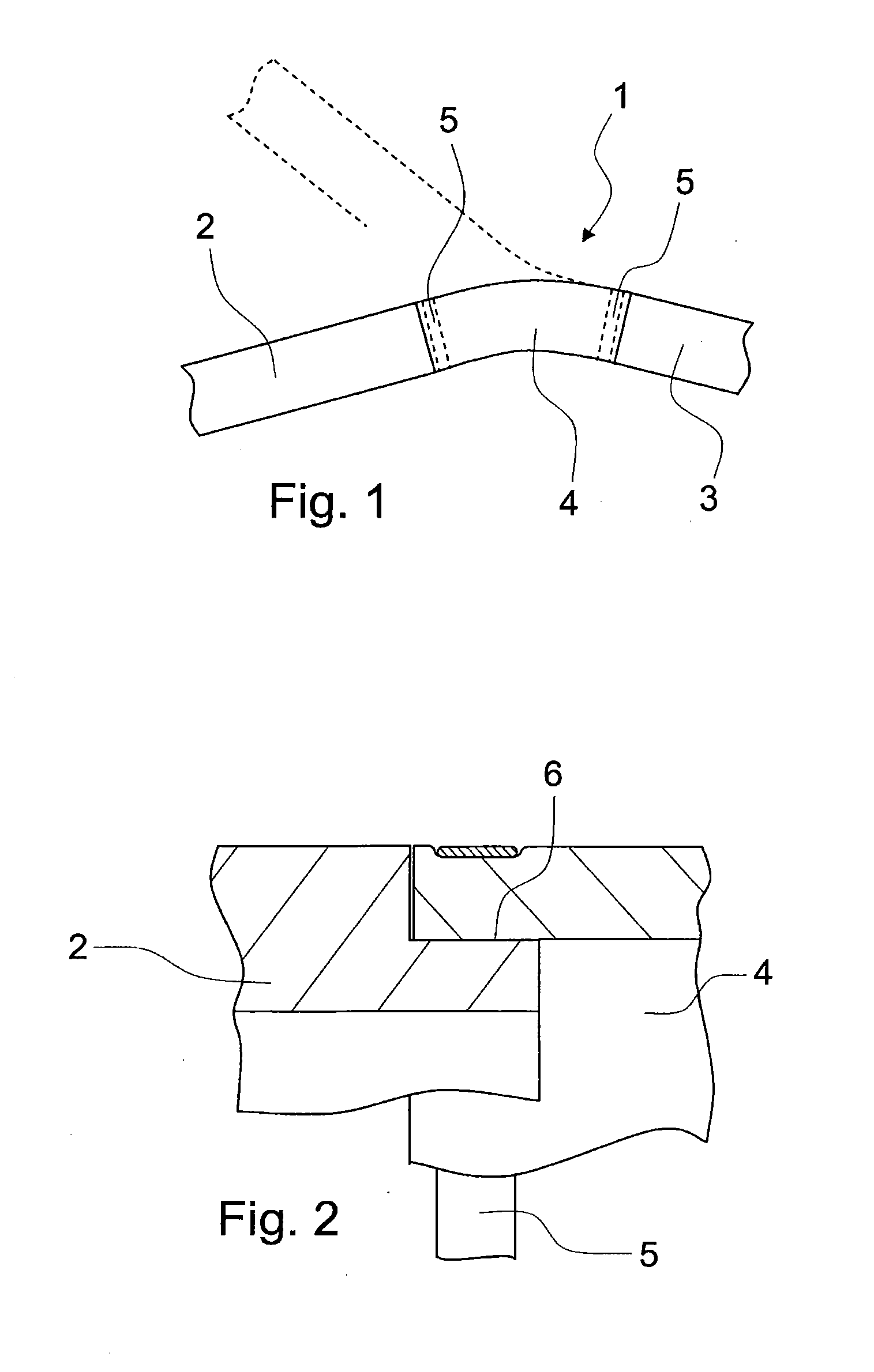
The present application is based upon and claims the benefit of priority from PCT/EP2014/000007 filed on Jan. 6, 2014, which claims benefit to DE 10 2013 003 315.2 filed on Feb. 28, 2013, the entire contents of each of which are incorporated herein by reference. 1. Field The present invention generally relates to endoscopes, and more particularly to an endoscope of the type referred to in claim 1 and also to a method for its production. 2. Prior Art In addition to rigid endoscopes, often enclosed by metal tubing, such as are used in urology and laparoscopy; generic endoscopes are known which have rigid and flexible portions that adjoin one another. Even endoscopes that are likely designated as completely flexible, such as those for intestinal examinations, are formed to be at least rigid on their proximal handling part, and have at that point a transition from a flexible to a rigid portion. In this case, the outer seal of the endoscope is of decisive importance, not only for endoscopes used in industrial applications, but in particular for medical endoscopes. The outer seal is then particularly important when the endoscope is being prepared. Preparation is understood to include cleaning and sterilization, thus activities that use liquids and e.g. also steam, from which the complicated inner workings of the endoscope, with its optical and electronic components, should be protected. Flexible portions of endoscopes have internally at most one stiffening framework, which consists of parts flexibly connected to one another or of helical spring type elements. An elastic hose, which guarantees the fluid-tight seal, always surrounds these flexible portions on the outside. The problem thereby is the sealing of the ends of the hose, which usually takes place generically by pushing the hose on and radially clamping it to the rigid portion. This displaces the entire sealing problem to the correct action of the clamping device. Clamping devices in the form of conventional hose clamps, as are common in many branches of technology, cannot be used here, as outwardly protruding and potentially sharp-edged parts are not allowed for use in a patient's body. A known solution consists in binding off the hose pushed onto the rigid portion using a thin plastic thread, similar to fishing line; the thread is tightened and the ends are knotted. The clamping device is subsequently completed by a cover with the aid of an adhesive material, a lacquer, or by using an adhesive tape. This construction provides good results for the user; however, there are also disadvantages during production. A mechanical production of the clamping device is not possible. It can only be completed by people with very dexterous fingers. High production costs result from this. An object consists in making an endoscope of the type listed in the beginning more economically with high safety. This problem is solved using the features of claim 1, and by a method according to claim 6. Accordingly, the endoscope uses a metal loop member, in which windings are welded. A clamping device of this type can be attached mechanically with a low error rate. By this means, costs are reduced and reliability is increased, thus in particular, patient safety in the case of medical use. Advantageously according to claim 2, an eyelet is provided on the end of the loop member. By means of this, a loop may be very easily formed, which facilitates the start of the looping process. Advantageously according to claim 3, the loop member is formed as a flat strip. This enables a high strength at low thickness and easy and secure welding across the width of the flat strip. In addition, the risk of injury is reduced due to the flat configuration. Advantageously according to claim 4, the flat strip is broadened in the area of the eyelet. This provides a high edge stability for the eyelet and the possibility of welding the flat strip, which returns here after wrapping the hose over the eyelet, wherein the broadened area protects the hose from the effects of the welding process. Advantageously according to claim 5, the loop member is formed as wire. By this means as well, advantageous embodiments of the clamping device may be created which have no sharp-edged points and are able to be safely welded, without damaging the hose. The production of the endoscope takes place advantageously using the feature of one of claims 6 through 8. In the drawings, the invention is presented schematically and by way of example. In the area shown, endoscope 1 includes three portions, namely a rigid portion 2 and a further rigid portion 3. These may both be formed e.g. as steel tubing on their depicted outer sides. A flexible portion 4 is arranged between the two rigid portions 2 and 3. Flexible portion 4 is formed on its outer side by an elastic hose which enables bending of flexible portion 4, as is indicated in Clamping devices 5 are arranged on the two end areas of flexible portion 4 (represented as dashed lines in In the end area of hose 4, which sits on reduced end area 6 of rigid portion 2, the clamping device 5 is placed externally around hose 4, which clamping device is shown schematically in Clamping device 5, in the form of loop member (referred to herein also with reference numeral 5) is tightened with force around elastic hose 4 and presses itself, as shown in The structure from This results in the placement position of the clamping device according to The first winding is shown in In contrast to the embodiments of Using a suitable winding machine, the metal wire, as shown in In this case, one welded seam 11 is always arranged between two windings. In total, there are thus four welded seams. These are arranged on a relatively short circumferential area along the contact line between each two windings. If the windings are wrapped sufficiently closely, then they may be welded here without damaging the hose lying below them. Deviating from the embodiment of welded seams 11 shown, an arrangement of welded seams in the direction of the axis of the endoscope, thus essentially transverse to the placement of the welded seams shown in As in the embodiment of While there has been shown and described what is considered to be preferred embodiments of the invention, it will, of course, be understood that various modifications and changes in form or detail could readily be made without departing from the spirit of the invention. It is therefore intended that the invention be not limited to the exact forms described and illustrated, but should be constructed to cover all modifications that may fall within the scope of the appended claims. An endoscope including: a flexible portion having an elastic hose; at least one rigid portion having at least at one end adjoined to the flexible portion at an end area, the at least one end being enclosed by the elastic hose; and a clamping device disposed over the elastic hose at the end area to sealingly clamp the flexible portion to the at least one rigid portion by applying a radial force to the end area, the clamping device including a loop member which is made of metal and which winds around the hose with at least two windings, and in which at least the two windings are welded to one another. 1. An endoscope comprising:
a flexible portion having an elastic hose; at least one rigid portion having, at least at one end adjoined to the flexible portion at an end area, the at least one end being enclosed by the elastic hose; and a clamping device disposed over the elastic hose at the end area to sealingly clamp the flexible portion to the at least one rigid portion by applying a radial force to the end area, the clamping device including a loop member which is made of metal and which winds around the hose with at least two windings, and in which at least the two windings are welded to one another. 2. The endoscope according to 3. The endoscope according to 4. The endoscope according to 5. The endoscope according to one of 6. A method for producing the endoscope of pushing the hose with the end area over the at least one rigid portion; looping the looped member at least once around the end area; tightening the loop member to apply the radial force to the end area, and welding the at least two windings of the loop member to one another. 7. The method according to 8. The method according to one of 9. (canceled)CROSS-REFERENCE TO RELATED APPLICATION
BACKGROUND
SUMMARY
BRIEF DESCRIPTION OF THE DRAWINGS
DETAILED DESCRIPTION