ELECTRICAL CONNECTOR WITH IMPRIVED GROUNDING BAR
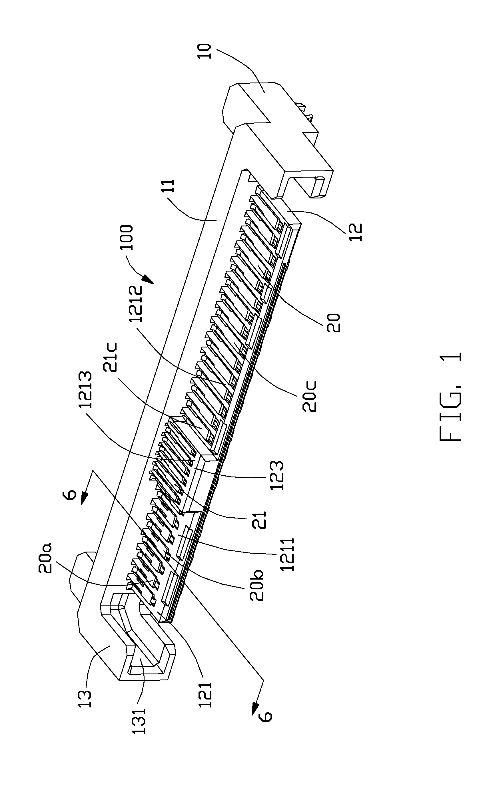
1. Field of the Invention The present invention relates to an electrical connector, and more particularly to an electrical connector used for high frequency transmission. 2. Description of the Related Art Chinese Patent Application No. 103515792A published on Jan. 15, 2014, discloses an electrical connector including an insulative housing and a plurality of conductive terminals retained in the insulative housing. The insulative housing defines a base portion, a tongue portion extending forwardly from the base portion and a plurality of terminal slots formed on the tongue portion, the tongue portion defines at least one mating surface. The conductive terminal defines a retaining portion retained in the insulative housing and a contacting portion disposed on the tongue portion. The conductive terminals includes a plurality of differential signal terminal pairs and grounding terminals, the grounding terminals are arranged on both sides of each differential signal terminal pairs. The retaining portions of the grounding terminals are electrically connected to each other and the contacting portions of the grounding terminals are also electrically connected to each other. The electrical connector has a good high-frequency transmission performance when the transmission rate is 12 Gbps. However, when the transmission rate is up to 24 Gbps, signal crosstalk phenomenon is more obvious which seriously affecting the quality of the high-frequency signal transmission. Therefore, an improved electrical connector is highly desired to meet overcome the requirement. An object of the present invention is to provide an electrical connector having good high frequency transmission performance. In order to achieve above-mentioned object, an electrical connector includes an insultive housing extending along a longitudinal direction and defining a base seat and a mating portion extending from the base seat along a mating direction perpendicular to the longitudinal direction, the mating portion defines a mating surface and a plurality of terminal slots recessed on the mating surface. A plurality of conductive terminals are retained in the terminal slots and include a plurality of differential signal terminal pairs and a plurality of grounding terminals located between the plurality of differential signal terminal pairs, each conductive terminal defines a contacting portion disposed on the mating surface, a retaining portion fixed to the base seat and a connecting portion extending outside of the base seat, the contacting portion of each grounding terminal has a free end extending toward the inside of the mating portion. A first grounding bar is facing to the contacting portions of the conductive terminals, and the free ends of the grounding terminals are abutting against the first grounding bar. And a second grounding bar is facing to the retaining portions of the conductive terminals and defines a base portion and a plurality of abutting portions extending from the base portion and abutting against the retaining portions of the grounding terminals. The first grounding bar and the second grounding bar are connected by a bridging portion thereof. Other objects, advantages and novel features of the invention will become more apparent from the following detailed description of the present embodiment when taken in conjunction with the accompanying drawings. Reference will now be made to the drawing figures to describe a preferred embodiment of the present invention in detail. Referring to The mating portion 12 defines a first surface 121 and a second surface 122 opposite to each other, and a convex portion 123 projecting from the first surface 121. The first surface 121 is divided into a first mating surface 1211, a second mating surface 1212 and a second mating surface 1213 formed on the convex portion 123, the second surface 122 is defined as a forth mating surface. Each conductive terminal 20 defines a contacting portion 21 disposed on said mating surface, a retaining portion 22 fixed to the base seat 11 and a connecting portion 23 projecting outside of the base seat 11. The retaining portion 22 is connecting the contacting portion 21 and the connecting portion 23, and the connecting portion 23 is used to secure to a circuit board or a cable by soldering or otherwise. The conductive terminals 20 are divided into a plurality of differential signal terminal 20 Referring to Referring to The first grounding bar 30 and the second grounding bar 40 are connected to each other by at least one bridging portion 43, which is eliminating the potential difference between the first grounding bar 30 and the second grounding bar 40 so that the potential difference between the connecting portions and the retaining portions of the grounding terminals is close to zero potential, thereby improving the performance of the high-frequency transmission and obtaining good transmission quality. The number of the bridging portion 43 is preferred two in present embodiment, considering the size of the bridging portion 43 and the manufacturing difficulty of the electrical connector. The bridge portion 43 is substantially horizontal “S” shape and includes a first arcuate portion 431 opening downwardly and a second arcuate portion 432 opening upwardly in order to obtain good flexibility and increase retention. The first arcuate portion 431 is extending from the base portion 41 and the second arcuate portion 432 is extending from the first arcuate portion 431 and abutting against the first grounding bar 30. It is worth noting that, the bridging portion 43 extends only toward the first grounding bar 30 and need to be connected to the first grounding bar 30 so that the first grounding bar 30 and the second grounding bar 40 are electrically connected to each other. And the abutting portions 42 are not necessarily face the first grounding bar 30, depending on the relative position between the conductive terminals 20 and the second grounding bar 40. It is to be understood, however, that even though numerous characteristics and advantages of the present invention have been set forth in the foregoing description, together with details of the structure and function of the invention, the disclosure is illustrative only, and changes may be made in detail, especially in matters of shape, size, and arrangement of parts within the principles of the invention to the full extent indicated by the board general meaning of the terms in which the appended claims are expressed. An electrical connector includes an insultive housing and defining a base seat and a mating portion extending from the base seat. A plurality of conductive terminals are retained in the mating portion and include a plurality of differential signal terminal pairs and grounding terminals, each conductive terminal defines a contacting portion disposed on the mating portion, a retaining portion fixed to the base seat and a connecting portion extending outside of the base seat, the contacting portion of each grounding terminal has a free end extending toward the inside of the mating portion and abutting against a first grounding bar. A second grounding bar defines a base portion and a plurality of abutting portions extending from the base portion and abutting against the retaining portions of the grounding terminals. The first grounding bar and the second grounding bar are connected by a bridging portion thereof. 1. An electrical connector, comprising:
an insultive housing extending along a longitudinal direction and defining a base seat and a mating portion extending from the base seat along a mating direction perpendicular to the longitudinal direction, the mating portion defining a mating surface and a plurality of terminal slots recessed on the mating surface; a plurality of conductive terminals retained in the terminal slots and comprising a plurality of differential signal terminal pairs and a plurality of grounding terminals located between the plurality of differential signal terminal pairs, each conductive terminal defining a contacting portion disposed on the mating surface, a retaining portion fixed to the base seat and a connecting portion extending outside of the base seat, the contacting portion of each grounding terminal having a free end extending toward the inside of the mating portion; a first grounding bar facing to the contacting portions of the conductive terminals, and the free ends of the grounding terminals abutting against the first grounding bar; and a second grounding bar facing to the retaining portions of the conductive terminals and defining a base portion and a plurality of abutting portions extending from the base portion and abutting against the retaining portions of the grounding terminals; wherein the first grounding bar and the second grounding bar are connected by a bridging portion thereof. 2. The electrical connector as described in 3. The electrical connector as described in 4. The electrical connector as described in 5. The electrical connector as described in 6. The electrical connector as described in 7. The electrical connector as described in 8. The electrical connector as described in 9. An electrical connector, comprising:
an insultive housing extending along a longitudinal direction and defining a base seat and a mating portion extending from the base seat along a mating direction perpendicular to the longitudinal direction, the mating portion defining opposite a first surface and a second surface and a convex portion projecting from the first surface, the first surface divided into a first mating surface, a second mating surface and a third mating surface formed on the convex portion due to the convex portion, and the second surface defined as a fourth mating surface; a plurality of conductive terminals retained in the insultive housing and defining a plurality of differential signal terminal pairs, grounding terminals and power terminals, each conductive terminal defining a contacting portion disposed on the mating surface, a retaining portion fixed to the base seat and a connecting portion extending outside of the base seat; a first grounding bar connected to the front ends of the contacting portions the grounding terminals; and a second grounding bar connected to the retaining portions of the grounding terminals; wherein the first grounding bar and the second grounding bar are connected by a bridging portion thereof. 10. The electrical connector as described in 11. The electrical connector as described in 12. The electrical connector as described in 13. The electrical connector as described in 14. An electrical connector comprising:
an insulative housing having a base seat extending along a longitudinal direction, a mating portion extending forwardly from the base seat in a front-to-back direction perpendicular to said longitudinal direction; a plurality of contacts disposed in the housing and categorized with signal contacts and grounding contacts, each of said contacts defining a front flat horizontal contact section exposed upon the mating portion, and a rear flat horizontal retaining section embedded within the base seat; a first grounding bar extending along the longitudinal direction and rearwardly assembled into a first middle slot of the mating portion frame from a front side of the housing; a second grounding bar extending along the longitudinal direction and forwardly assembled into a second middle slot of the base seat from a rear side of the housing; wherein the first grounding bar and the second grounding bar are essentially located at a same level, and the second grounding bar has a plurality of spring fingers extending in at least a vertical direction perpendicular to both said longitudinal direction and said front-to-back direction, to selectively mechanically and electrically connect to the retaining sections of the grounding contacts, respectively, and at least one spring tang extending in at least the front-to-back direction to mechanically and electrically connect to the first grounding bar. 15. The electrical connector as claimed in 16. The electrical connector as claimed in 17. The electrical connector as claimed in 18. The electrical connector as claimed in 19. The electrical connector as claimed in BACKGROUND OF THE INVENTION
BRIEF SUMMARY OF THE INVENTION
BRIEF DESCRIPTION OF THE DRAWINGS
DESCRIPTION OF PREFERRED EMBODIMENT OF THE INVENTION