AUGMENTING A FLOODWALL WITH A COLLAR
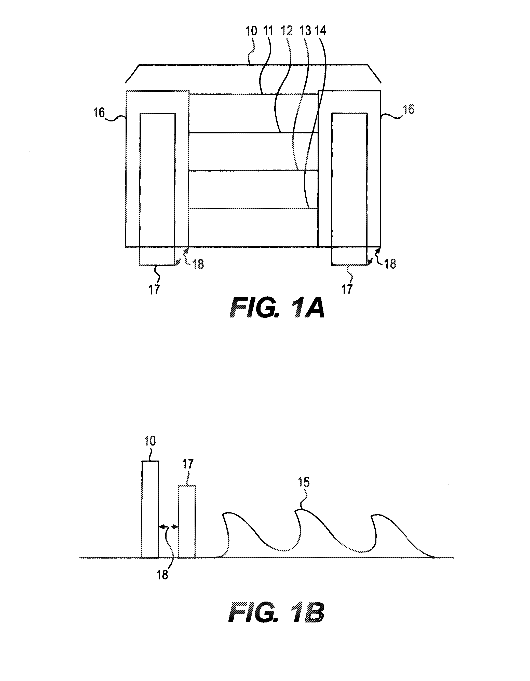
This patent application claims priority to U.S. Provisional Application No. 62/029,250, filed Jul. 25, 2014, entitled “Augmenting a Floodwall with a Collar,” now pending. This patent application contains the entire Detailed Description of U.S. Patent Application No. 62/029,250. Buildings and other locations often times are built near bodies of water. Various phenomena may cause the body of water to rise, and potentially cause deleterious effects associated with flooding. As storms become more frequent and larger, and other phenomena, such as climate change becomes an issue, flooding may become more common. One such solution is to provide a floodwall. The floodwall may be erected in between the source of water and the building/location. Thus, even if the water rises over a certain level, the floodwall may effectively block the water out. Several problems exist with floodwalls. One issue is that the floodwall may not be aesthetically pleasing. Thus, a general facade of a building/location may be drastically altered by the placement of a floodwall. A workaround to this problem is to provide removable floodwalls. Removable floodwalls have been implemented in numerous locations around the world. The removable floodwall allows the floodwall to be erected when needed, or during a particularly flood sensitive time period. The floodwall 10 includes a plurality of removable planks 11-14, a post 16. The removable planks 11-14 are stackable, and may be selectively provided based on need or an implementer of the floodwall 10's preference. As shown in Also shown in The bollard 17 may be reinforced into the ground by various techniques, such as, but not limited to, a concrete attachment to the ground. Also shown in The bollard 17 is merely one type of existing structure that may be near or around the floodwall 10. However, in order to simplify the explanation of the aspects disclosed herein, the bollard 17 will be employed to illustrate the concepts disclosed herein. However, one of ordinary skill in the art may substitute the bollard 17 with similar existing elements in or around a floodwall 10. As water 15 hits the floodwall 10, as shown in the side-view, the floodwall 10 provides a certain amount of protection against the water 15. However, as water patterns change, flooding becomes more of an issue, and climate change also become more pernicious—the singular solution to preventing floods may not be adequate. Thus, existing floodwalls may be incapable of being adequate for the size and force of flooding that was not anticipated. However, due to the introduction of an existing structure, for example, the bollard 17, modifying a floodwall 10 to be stronger and more capable of being flood and wind resistance may be difficult. A system, method and collar for augmenting a floodwall are disclosed herein. The collar includes metal shell conformed in the shape of bollard, and is slide-able over the bollard. The collar is capable of being locked to the bollard by a bolt. The detailed description refers to the following drawings, in which like numerals refer to like items, and in which: The invention is described more fully hereinafter with references to the accompanying drawings, in which exemplary embodiments of the invention are shown. This invention may, however, be embodied in many different forms and should not be construed as limited to the embodiments set forth herein. Rather, these exemplary embodiments are provided so that this disclosure is thorough, and will fully convey the scope of the invention to those skilled in the art. It will be understood that for the purposes of this disclosure, “at least one of each” will be interpreted to mean any combination the enumerated elements following the respective language, including combination of multiples of the enumerated elements. For example, “at least one of X, Y, and Z” will be construed to mean X only, Y only, Z only, or any combination of two or more items X, Y, and Z (e.g. XYZ, XZ, YZ, X). Throughout the drawings and the detailed description, unless otherwise described, the same drawing reference numerals are understood to refer to the same elements, features, and structures. The relative size and depiction of these elements may be exaggerated for clarity, illustration, and convenience. As explained in the Background section, floodwalls, such as floodwall 10, may be implemented to help aid and protect an environment, building, or area from environmental conditions, such as flooding. However, due to legacy conditions, the certain areas may not include any sort of flooding protection. One such solution is a removable floodwall, such as floodwall 10. Floodwall 10 provides an ability to prevent an area from being engulfed by waters, and the floodwall 10 may be built to be strong enough to avoid being knocked down by winds. In order for floodwall 10 to be effective, the strength and durability of the floodwall 10 needs to match and anticipate flooding situations. However, various conditions may cause flooding to be stochastic and unpredictable. Thus, floodwalls that are implemented at a certain period of time and context, may not be adequate to deal with future flooding conditions. Disclosed herein are methods and systems for augmenting a floodwall system. By employing the aspects disclosed herein, an existing floodwall 10 may be strengthened to handle future and more powerful floods. The aspects disclosed herein allow and provide for implementation with existing structures, such as a bollard 17 described in the Background section. The aspects disclosed herein have been tested and experimented with, and have been shown to improve existing floodwall implementations. Referring to The bollard 27 now includes a hole 28, with two openings. The hole 28 is substantially parallel with the placement of the removable planks 21-24. The hole 28 may be pre-manufactured with the bollard 27, or alternatively, be added through any drilling process on an already existing bollard installed near a floodwall. Also shown in The collar 30 is attached to the post 26 via a connection technique at location 35. As both the collar 30 and the post 26 may be metal, an approach to effectuate the attachment at location 35 may be through a welding process. Welding ensures that the post 26 and collar 30 are attached in a strong enough and stable way. The collar 30 is placed over an existing bollard 27, as shown in The collar 30 is designed with minimum clearance—for example, in one example it may be provided with a clearance of less than a quarter inch—so as to make it easy to slide the post 26 and collar 30 integrated assembly over the bollard 27. The collar height is designed to transfer the loads handling the bending/ turnover forces created by the water on the wall height. The post 26 and collar 30 may be connected via three pin connectors, and positioned using a welder's alignment pin tool. The various pins and bolt 40 may be attached via a wing nut fastened to provide a secure connection. The collar 30 also includes two openings 33 and 34. The collar 30 is ideally shaped to fit over an existing bollard 27, so the collar 30 is shaped to be in a shell that fits over the bollard 27. The collar 30 may then be slid over the bollard 27, thereby providing a snug fit with the bollard 27. Thus, depending on the shape of bollard 27, the shape of the collar 30 may be designed accordingly. In The collar 30, as shown in As shown in Thus, in the floodwall 20 shown in In operation 510, a determination of whether a bollard is situated in an area of a floodwall installation is made. If a bollard is placed, the method 500 proceeds to operation 520. If not, the method 500 proceeds to end. As explained above, this analysis may be performed via numerous existing structures, such as other permanent or semi-permanent structures installed in a location. In operation 520, a determination is made as to whether the existing bollard is modifiable. If the existing bollard is modifiable, holes, such as hole 28, are inserted into the bollard (operation 521). If not, the bollard is replaced with a modifiable bollard (operation 522), and holes are inserted into the modifiable bollard (operation 521). The inclusion of operation 522 may be omitted in most cases. This is due to the fact that many bollards or existing structures are not modifiable or may not be manipulated by the floodwall's installers. In operation 530, a collar, as described above is affixed to a post implemented in a removable floodwall installation. As explained above, the post and the collar may be pre-welded together to ensure a rigid and secure attachment. The method 500 then proceeds to operation 540. In operation 540, the collar is placed over the bollard. The collar may incorporate holes as well. The holes of the elements, the collar and the bollard, may significantly line up with each other. As the collar is placed over the bollard, the post may be installed as well. In this way, the collar, the bollard and the post at various locations and installation spots along the floodwall may significantly line up. In operation 550, a bolt may be inserted through the two elements, the collar and bollard. The bolt allows the two elements to substantially lock together. Thus, employing the aspects disclosed herein, an existing floodwall (e.g. removable floodwall systems), may be strengthened. Due to the necessity to have a system that is easy to implement, cheap, and portable, the aspects disclosed herein allow a floodwall implementer to accomplish a more efficient and cost-effective design. Further, because floodwall systems are being improved upon, end users of the floodwall may realize safer communities, free of the deleterious effects associated with modern and common environmental phenomena. It will be apparent to those skilled in the art that various modifications and variation can be made in the present invention without departing from the spirit or scope of the invention. Thus, it is intended that the present invention cover the modifications and variations of this invention provided they come within the scope of the appended claims and their equivalents. A system, method and collar for augmenting a floodwall are disclosed herein. The collar includes metal shell conformed in the shape of bollard, and is slideable over the bollard. The collar is capable of being locked to the bollard by a bolt. The collar is welded or attached to a post of the floodwall. The floodwall may be a removable floodwall installation. 1. A collar for augmenting a floodwall, the collar comprising:
a metal shell fitted to conform to a bollard, the metal shell including a first opening and a second opening; a first hole and a second hole included on the metal shell, wherein the first hole and the second hole line-up significantly with a bollard hole, and the collar is welded to a post of the floodwall. 2. The collar of 3. The collar of 4. The collar of 5. A removable floodwall system, the system comprising:
a plurality of posts to receive a plurality of removable planks disposed in-between the plurality of posts; and a plurality of collars, each of the collars being a metal shell conformed to fit each of a plurality of bollards, wherein each of the plurality of posts is welded to at least some of the plurality of collars. 6. The system according to a first hole and a second hole included on the metal shell, wherein the first hole and the second hole line-up significantly with a bollard hole. 7. The system of 8. The system of 9. A method for augmenting a floodwall with a collar, the method comprising:
inserting a hole in a bollard situated with a floodwall; conforming a metal shell in the shape of the bollard; inserting a first hole and a second hole to line-up with the bollard hole; welding the metal shell with a post of the floodwall; sliding the metal shell over the bollard; and locking the metal shell and the bollard with a bolt.CLAIM TO PRIORITY
BACKGROUND
SUMMARY
DESCRIPTION OF THE DRAWINGS
DETAILED DESCRIPTION