SIGN VENTILATION SYSTEM
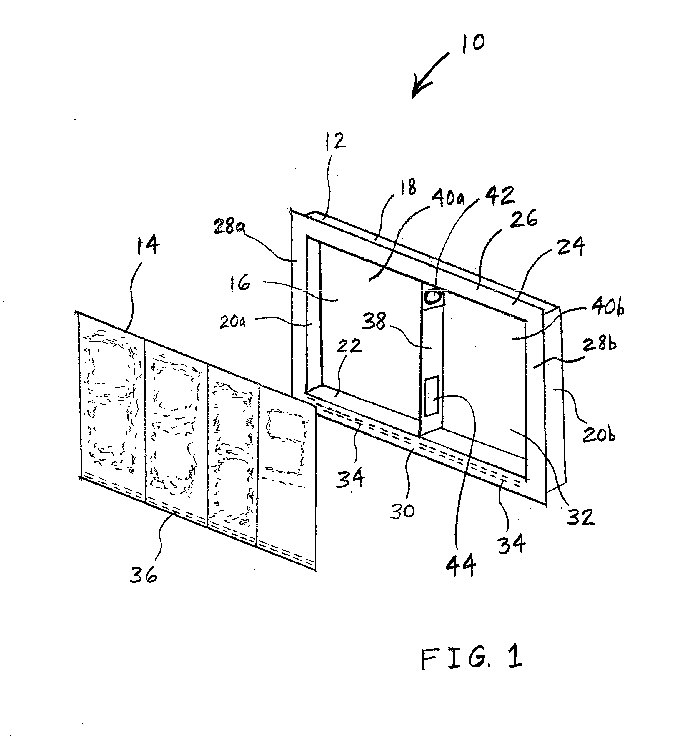
This application is a continuation of U.S. patent application Ser. No. 13/751,882 filed Jan. 28, 2013, entitled “Sign Ventilation System”, which claims the benefit of provisional application 61/591,796, filed Jan. 27, 2012, entitled “Multi-Chamber Sign Ventilation System”, by applicants Ryan Messmore, Byron Hall, Larry Smith and Jeff Koebrich, the disclosures of which are expressly incorporated by reference herein in their entirety. 1. Field of the Invention The present invention relates to a system and method of ventilating an electronic sign. 2. Description of the Related Art LED outdoor signs require ventilation to cool the internal electronics and also to remove heat from the backs of the LED modules or tiles that form the face of the cabinet. Since the front of the sign is made up of LED modules, the back or sides are used for ventilation (air intake and exhaust). Customers often prefer to mount the cabinets against walls or enclosed in structures for esthetic reasons. This blocks the fresh air supply to the back or sides, leaving the front as the only option for ventilation. Earlier designs pulled air in from the sides and exhausted out the front using small holes or louvers between the pixel elements of the sign. This approach is limited in that the cool air may not reach the center of a relatively large sign. The invention may provide a relatively large electronic sign that is divided into horizontally adjacent chambers. Each of the chambers may have its own ventilation system. In this way, a sign of any size may be provided with adequate ventilation throughout its width. Each chamber may include a vertical partition in the middle of the chamber such that the chamber is divided by the partition into two sections. The partition may include one or more throughholes to enable air to pass between the two sections. An electric fan is installed in one of the throughholes in order to force air to move from one section to the other section. The bottom side of each section of the chamber includes a series or array of vent holes to allow air to be drawn by the fan into one of the sections, be blown by the fan into the adjacent section, and to be blown out of the adjacent section through the vent holes. The vent holes may include baffles to prevent moisture, insects, and animals from entering the sign. The invention comprises, in one form thereof, an electronic sign that is divided into one or more horizontally aligned chambers. Each chamber has a vertical partition in its middle holding one or more fans to move air from one side of the partition to the other. The air enters and exhausts from the chamber via a baffled slot across the bottom of the sign. The invention comprises, in another form thereof, a ventilated electronic sign module including a substantially planar-shaped lighting module emitting light that is visible to a viewer of the sign. A cabinet supportingly engages the lighting module. The cabinet includes a rear wall, two opposing side walls, a top wall and a bottom wall. The rear wall is disposed opposite the lighting module such that an air chamber is defined between the cabinet and the lighting module. A substantially vertical partition is disposed within the air chamber and extends between the bottom wall and the top wall, and between the lighting module and the rear wall. The partition divides the air chamber into a first section and a second section. An electric fan is disposed within the cabinet and transfers air from the first section to the second section. The cabinet and/or the lighting module include a plurality of throughholes fluidly interconnecting the air chamber to ambient air. A first subset of the throughholes are more closely fluidly connected to the first section than to the second section. A second subset of the throughholes are more closely fluidly connected to the second section than to the first section. The invention comprises, in yet another form thereof, an electronic sign including a plurality of ventilated electronic sign modules. The modules are substantially aligned in a horizontal direction. Each module is disposed horizontally adjacent to one or two other of the modules. Each of the modules includes a substantially planar-shaped lighting module emitting light that is visible to a viewer of the sign. A cabinet supportingly engages the lighting module. The cabinet includes a rear wall, two opposing side walls, a top wall and a bottom wall. The rear wall is disposed opposite the lighting module such that an air chamber is defined between the cabinet and the lighting module. A substantially vertical partition is disposed within the air chamber and extends between the bottom wall and the top wall, and between the lighting module and the rear wall. The partition divides the air chamber into a first section and a second section. An electric fan is disposed within the cabinet or within the lighting module and transfers air from the first section to the second section. The cabinet and/or the lighting module include a plurality of throughholes fluidly interconnecting the air chamber to ambient air. A first subset of the throughholes are more closely fluidly connected to the first section than to the second section. A second subset of the throughholes are more closely fluidly connected to the second section than to the first section. The invention comprises, in still another form thereof, an electronic sign including a plurality of ventilated electronic sign modules. The modules are substantially aligned in a horizontal direction. Each module is disposed horizontally adjacent to one or two other of the modules. Each of the modules includes a substantially planar-shaped lighting module emitting light that is visible to a viewer of the sign. A cabinet supportingly engages the lighting module. The cabinet includes a rear wall, two opposing side walls, a top wall and a bottom wall. The rear wall is disposed opposite the lighting module such that an air chamber is defined between the cabinet and the lighting module. A substantially vertical partition is disposed within the air chamber and extends substantially an entire span between the bottom wall and the top wall, and extends substantially an entire span between the lighting module and the rear wall. The partition divides the air chamber into a first section and a second section. An electric fan is within the partition and transfers air from the first section to the second section. The cabinet and/or the lighting module have a plurality of throughholes fluidly interconnecting the air chamber to ambient air. A first subset of the throughholes are more closely fluidly connected to the first section than to the second section. A second subset of the throughholes are more closely fluidly connected to the second section than to the first section. An advantage of the invention is that a middle portion of a sign that is relatively wide may be effectively cooled. Referring now to Digit panel 14 includes light emitting diodes (LEDs) and associated electronics for powering and controlling the operation of the LEDs. In the specific embodiment of Bottom portion 30 of frame 24 may include a series of throughholes or louvers 34 through which air chamber 32 may be in fluid communication with ambient air. Digit panel 14 may include throughholes 36 along a bottom edge of panel 14 wherein throughholes 36 are aligned with louvers 34 such that panel 14 does not block the fluid communication between air chamber 32 and ambient air. In another embodiment, however, panel 14 does not extend downwardly as far as louvers 34, and thus panel 14 does not include throughholes 36 because panel 14 does not block fluid communication between air chamber 32 and ambient air anyway. A vertical partition 38 may be disposed in air chamber 32 between side walls 20 In another embodiment (not shown), the fan is not within partition 38, but rather is disposed in digit panel 14, adjacent to an upper portion of a front edge of partition 38. In this embodiment, the fan is still fluidly connected to each of the two sections of the air chamber, and thus is configured to transfer air from one of the sections to the other. Advantageously, the fan may be easily connected to electrical power with digit panel 14. The embodiment of A fan 242 More generally, in a longer series of adjacent chambers, such as chambers 332 In order to further reduce the turbulence caused by adjacent oppositely directed flows of air, a cabinet frame 324 ( Another embodiment of a cabinet 512 of the present invention is shown in A vertical partition 538 may be disposed in air chamber 532 between side walls 520 As shown in The structure of cabinet 512 below fan 542 It is to be understood that a series of ventilated sign modules, each having its own cabinet 512, may be placed in a line or series as shown in A further embodiment of a cabinet 612 of the present invention is shown in A vertical partition 638 may be disposed in air chamber 632 between side walls 620 As shown in The structure of cabinet 612 below bottom wall 622 and slanted wall 623 in section 640 It is to be understood that a series of ventilated sign modules, each having its own cabinet 612, may be placed in a line or series as shown in While this invention has been described as having an exemplary design, the present invention may be further modified within the spirit and scope of this disclosure. This application is therefore intended to cover any variations, uses, or adaptations of the invention using its general principles. An electronic sign includes a planar lighting module emitting visible light. A cabinet supportingly engages the lighting module. An air chamber is between the cabinet and the lighting module. A vertical partition is within the air chamber and extends between a bottom wall and a top wall of the cabinet, and between the lighting module and a rear wall of the cabinet. The partition divides the air chamber into first and second sections. An electric fan is within the cabinet and transfers air from the first to the second section. The cabinet and/or the lighting module include a plurality of throughholes fluidly interconnecting the air chamber to ambient air. A first subset of the throughholes are more closely fluidly connected to the first section than to the second section. A second subset of the throughholes are more closely fluidly connected to the second section than to the first section. 1. A ventilated electronic sign module, comprising:
a substantially planar-shaped lighting module configured to emit light that is visible to a viewer of the sign; a cabinet supportingly engaging the lighting module, the cabinet including a bottom portion, a rear wall, two opposing side walls, a top wall and a bottom wall, the rear wall being disposed opposite the lighting module such that an air chamber is defined between the cabinet and the lighting module; a substantially vertical partition disposed within the air chamber and extending between the bottom wall and the top wall, and between the lighting module and the rear wall, the partition dividing the air chamber into a first section and a second section; and an electric fan disposed within the cabinet and configured to transfer air from the first section to the second section; wherein the cabinet and/or the lighting module include a plurality of throughholes disposed at the bottom portion and fluidly interconnecting the air chamber to ambient air, a first subset of the throughholes being more closely fluidly connected to the first section than to the second section, a second subset of the throughholes being more closely fluidly connected to the second section than to the first section, and wherein the electric fan is configured to draw air from outside the cabinet through the first subset of throughholes and is configured to blow air out of the cabinet through of the second subset of throughholes. 2. The module of 3. The module of 4. The module of 5. The module of 6. An electronic sign, comprising a plurality of ventilated electronic sign modules, the modules being substantially aligned in a horizontal direction and each module being disposed horizontally adjacent to one or two other said modules, each said module including:
a substantially planar-shaped lighting module configured to emit light that is visible to a viewer of the sign; a cabinet supportingly engaging the lighting module, the cabinet having a bottom portion, a rear wall, two opposing side walls, a top wall and a bottom wall, the rear wall being disposed opposite the lighting module such that an air chamber is defined between the cabinet and the lighting module; a substantially vertical partition disposed within the air chamber and extending between the bottom wall and the top wall, and between the lighting module and the rear wall, the partition dividing the air chamber into a first section and a second section; and an electric fan disposed within the cabinet or the lighting module and configured to transfer air from the first section to the second section; wherein the cabinet and/or the lighting module have a plurality of throughholes disposed at the bottom portion and fluidly interconnecting the air chamber to ambient air, a first subset of the throughholes being more closely fluidly connected to the first section than to the second section, a second subset of the throughholes being more closely fluidly connected to the second section than to the first section; and wherein the electric fan is configured to draw air from outside the cabinet through the first subset of throughholes and is configured to blow air out of the cabinet through of the second subset of throughholes. 7. The sign of 8. The sign of 9. The sign of 10. An electronic sign, comprising a plurality of ventilated electronic sign modules, the modules being substantially aligned in a horizontal direction and each module being disposed horizontally adjacent to one or two other said modules, each said module including:
a substantially planar-shaped lighting module configured to emit light that is visible to a viewer of the sign; a cabinet supportingly engaging the lighting module, the cabinet having a bottom portion, a rear wall, two opposing side walls, a top wall and a bottom wall, the rear wall being disposed opposite the lighting module such that an air chamber is defined between the cabinet and the lighting module; a substantially vertical partition disposed within the air chamber and extending substantially an entire span between the bottom wall and the top wall, and extending substantially an entire span between the lighting module and the rear wall, the partition dividing the air chamber into a first section and a second section; and an electric fan disposed within the partition and configured to transfer air from the first section to the second section; wherein the cabinet and/or the lighting module have a plurality of throughholes disposed at the bottom portion and fluidly interconnecting the air chamber to ambient air, a first subset of the throughholes being more closely fluidly connected to the first section than to the second section, a second subset of the throughholes being more closely fluidly connected to the second section than to the first section, and wherein the electric fan is configured to draw air from outside the cabinet through the first subset of throughholes and is configured to blow air out of the cabinet through of the second subset of throughholes. 11. The sign of 12. The sign of 13. The module of 14. The module of 15. The sign of 16. The sign of 17. The sign of 18. The sign of RELATED APPLICATIONS
BACKGROUND OF THE INVENTION
SUMMARY OF THE INVENTION
BRIEF DESCRIPTION OF THE DRAWINGS
DESCRIPTION OF THE PRESENT INVENTION