MULTI-CONDUIT CONNECTORS AND METHODS FOR NEGATIVE PRESSURE WOUND THERAPY
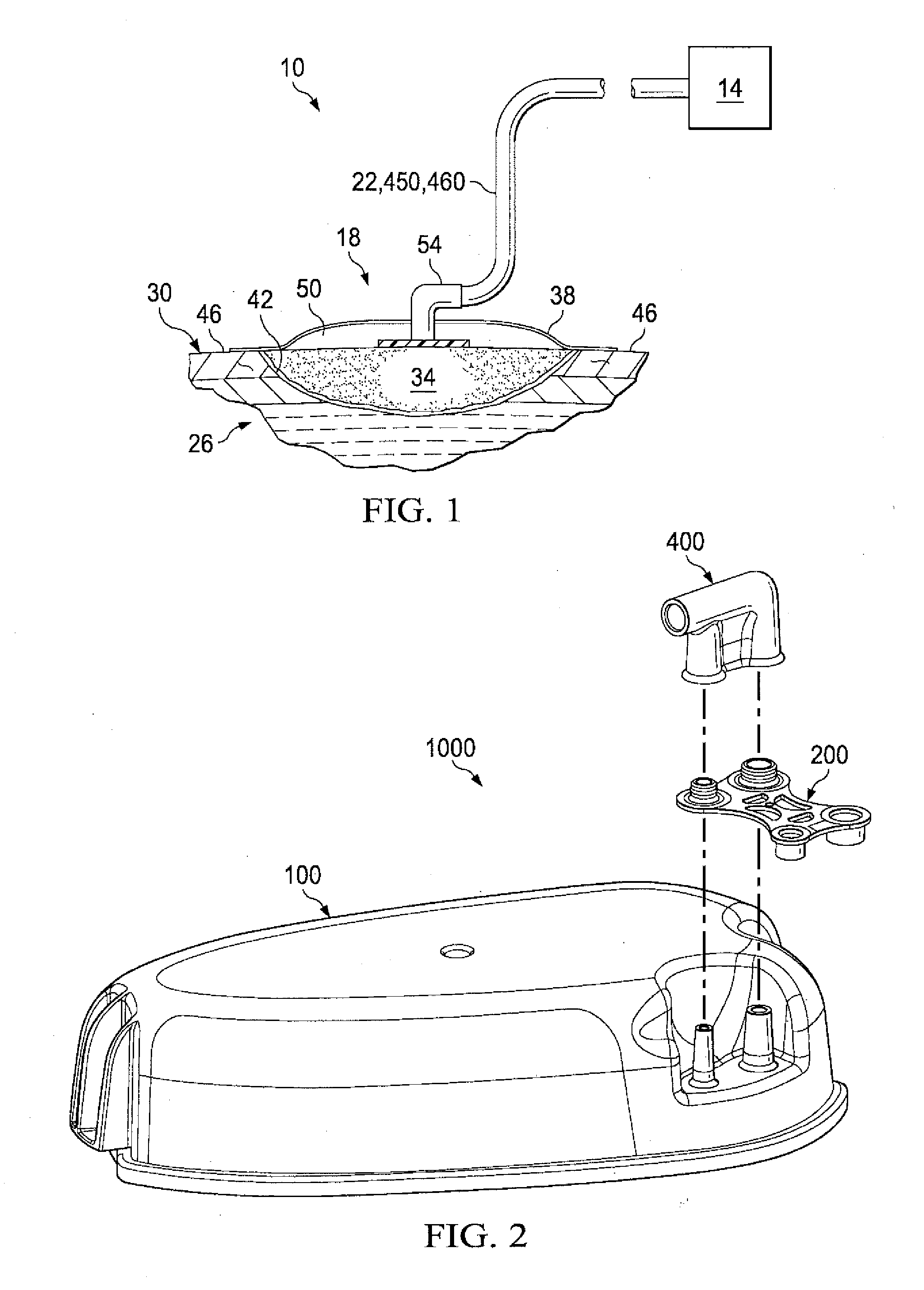
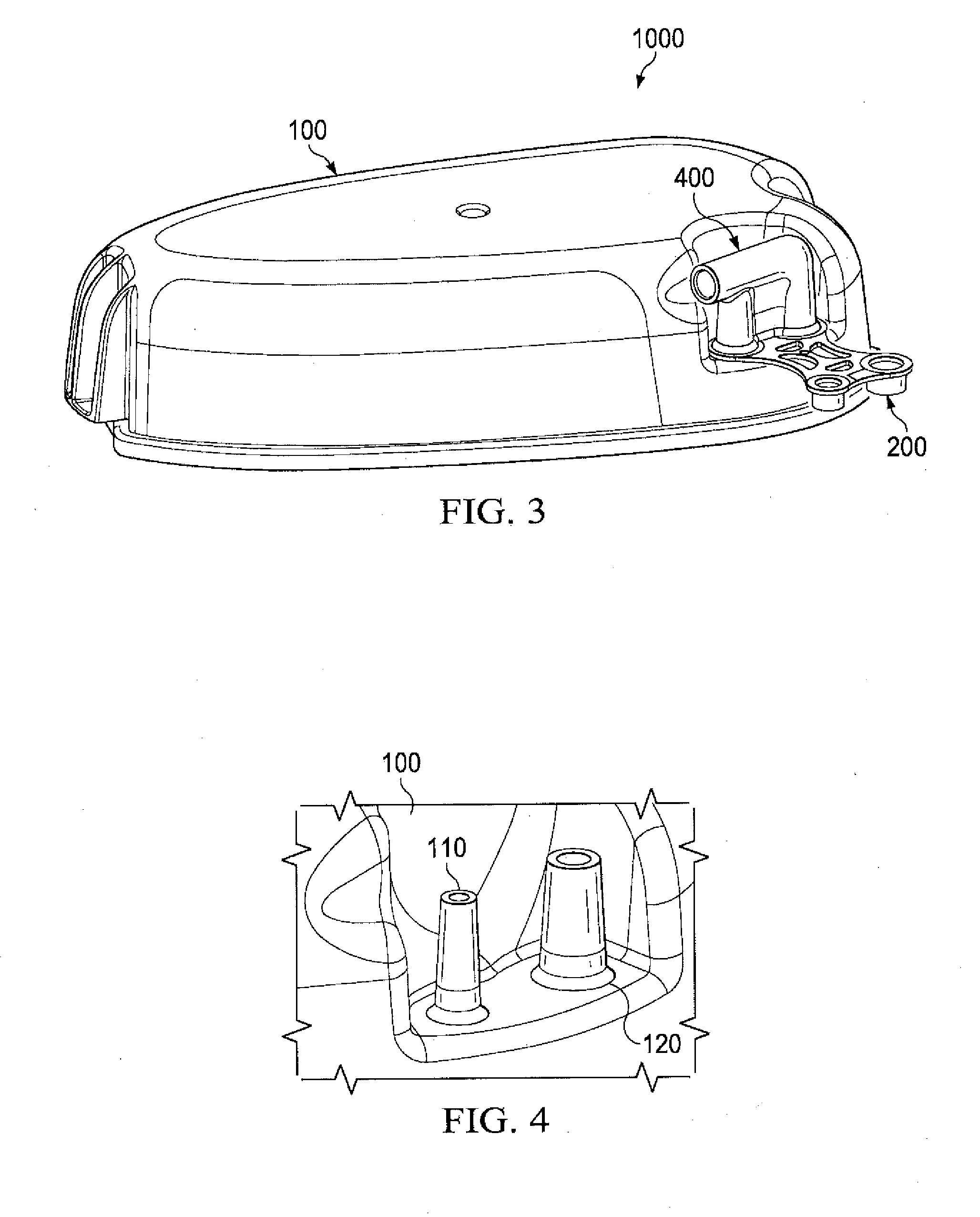
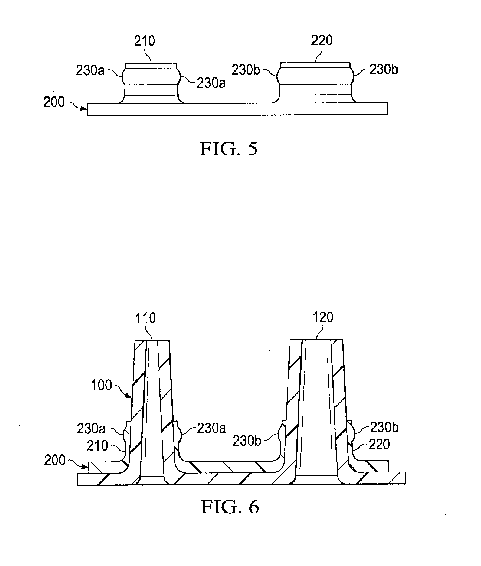
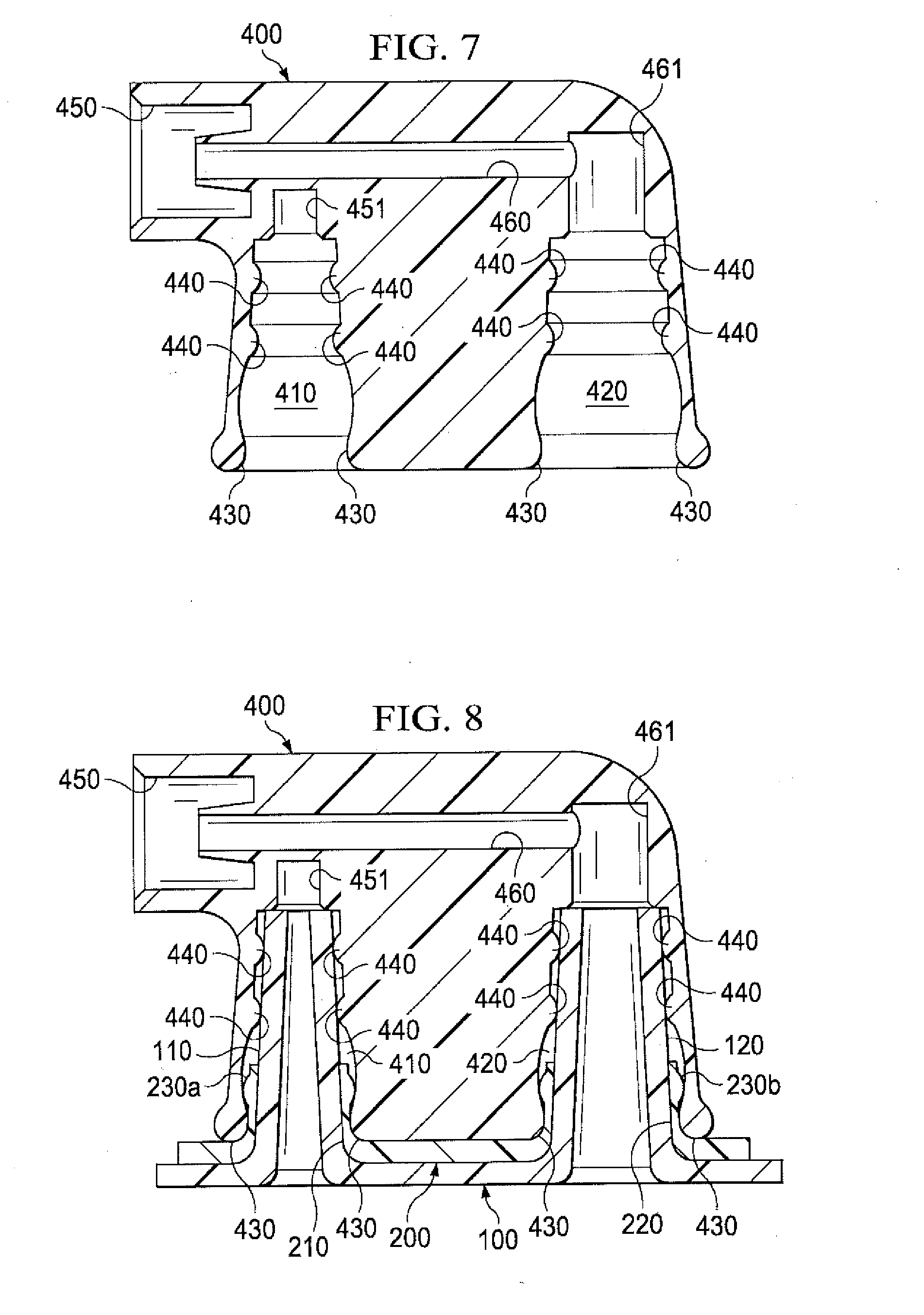
This application is a continuation of U.S. patent application Ser. No. 13/874,974, filed May 1, 2013, which is a continuation of U.S. patent application Ser. No. 13/017,857, filed Jan. 31, 2011, now U.S. Pat. No. 8,454,567, which claims priority to U.S. Provisional Patent Application Ser. No. 61/300,362 filed Feb. 1, 2010. This provisional application is expressly incorporated by reference. 1. Field of the Invention The present invention relates generally to healing of wounds and wound-treatment therapies. More particularly, but not by way of limitation, the present invention relates to apparatuses and methods for a multi-conduit connector used in negative pressure wound therapy (NPWT) apparatuses and methods. 2. Background Information Clinical studies and practice have shown that providing a reduced pressure in proximity to a tissue site augments and accelerates the growth of new tissue at the tissue site. The applications of this phenomenon are numerous, but application of reduced pressure has been particularly successful in treating wounds. This treatment (frequently referred to in the medical community as “negative pressure wound therapy,” “reduced pressure therapy,” or “vacuum therapy”) provides a number of benefits, including faster healing and increased formulation of granulation tissue. Typically, reduced pressure is applied to tissue through a wound insert (e.g., a porous pad or other manifold device). While NPWT has been highly successful in the promotion of wound closure, healing many wounds previously thought largely untreatable, some difficulty remains. One common component of an NPWT system is a device or structure (e.g., a multi-conduit connector) that connects a canister housing a vacuum, a fluid receptacle, or both to a medical tubeset. The tubeset may be used to deliver negative pressure to the wound site, to remove exudates from the wound site, or both. While NPWT has been used for some time, multi-conduit connectors can be expensive to manufacture and difficult to install. Often, a user is unable to determine whether a connection has been made between the multi-conduit connector and the canister. The present disclosure includes embodiments of multi-conduit connectors. Specific embodiments comprise multi-conduit connector apparatuses for use in negative pressure wound therapy (NPWT) apparatuses and methods for installing multi-conduit connector apparatuses in NPWT apparatuses. Specific embodiments include a multi-conduit connector apparatus comprising a canister lid comprising a first nipple and a second nipple; a cap sleeve, comprising a first annular sleeve and a second annular sleeve, where the first annular sleeve engages the first nipple and the second annular sleeve engages the second nipple; and a housing, comprising a first port, comprising a plurality of sealing ridges, the plurality of sealing ridges creating a seal with the first nipple; a second port, comprising a plurality of sealing ridges, the plurality of sealing ridges creating a seal with the second nipple; a first conduit comprising a first outlet, where the first outlet is in fluid communication with the first nipple; and a second conduit comprising a second outlet, where the second outlet is in fluid communication with the second nipple. In certain embodiments, the first conduit is coupled to the first port. The second conduit may be coupled to the second port. The first conduit, the second conduit, or both may be coupled to a wound dressing. The first conduit and/or the second conduit may be comprised of a single lumen or multiple lumens. Other embodiments may comprise a multi-conduit connector apparatus comprising: a canister lid comprising a first nipple and a second nipple; a cap sleeve, comprising: a first annular sleeve comprising a first clearance shoulder, where the first annular sleeve engages the first nipple; and a second annular sleeve comprising a second clearance shoulder, where the second annular sleeve engages the second nipple; and a housing, comprising: a first port, comprising: a plurality of sealing ridges, the plurality of sealing ridges creating a seal with the first nipple; and a first engagement tab, the first engagement tab engaging the first clearance shoulder; a second port, comprising: a plurality of sealing ridges, the plurality of sealing ridges creating a seal with the second nipple; and a second engagement tab, the second engagement tab engaging the second clearance shoulder; a first conduit comprising a first outlet, where the first outlet is in fluid communication with the first nipple; and a second conduit comprising a second outlet, where the second outlet is in fluid communication with the second nipple. In certain embodiments, the first outlet is coupled to the first nipple. In other embodiments, the second outlet is coupled to the second nipple. In specific embodiments, the first conduit or the second conduit may be coupled to a wound site. In some embodiments, the first nipple or the second nipple may be a tapered nipple. In some embodiments, the cap sleeve may further comprises a sleeve lid and/or a hinge. The cap sleeve lid may be comprised of plastic or rubber in certain embodiments. In certain embodiments, the clearance shoulder is substantially a ring. In other embodiments, the clearance shoulder is deformable. Still other embodiments comprise a multi-conduit connector apparatus comprising: a canister lid comprising a first nipple and a second nipple, where the first nipple further comprises a first clearance shoulder, and the second nipple further comprises a second clearance shoulder; and a housing, comprising: a first port, comprising: a plurality of sealing ridges, the plurality of sealing ridges creating a seal with the first nipple; and a first engagement tab, the first engagement tab engaging the first clearance shoulder; a second port, comprising: a plurality of sealing ridges, the plurality of sealing ridges creating a seal with the second nipple; and a second engagement tab, the second engagement tab engaging the second clearance shoulder; a first conduit comprising: a first outlet, where the first outlet is coupled to the first nipple, and where the multi-lumen coupling member is configured to be coupled to a wound site; and a second conduit comprising: a second outlet, where the second outlet is coupled to the second nipple, and where the second conduit member is configured to be coupled to a wound site. Other embodiments may comprise obtaining a multi-conduit connector apparatus comprising: a canister lid comprising a first nipple and a second nipple; a cap sleeve, comprising: a first annular sleeve comprising a first clearance shoulder, where the first annular sleeve engages the first nipple; and a second annular sleeve comprising a second clearance shoulder, where the second annular sleeve engages the second nipple; and a housing, comprising: a first port, comprising: a plurality of sealing ridges, the plurality of sealing ridges creating a seal with the first nipple; and a first engagement tab, the first engagement tab engaging the first clearance shoulder, a second port, comprising: a plurality of sealing ridges, the plurality of sealing ridges creating a seal with the second nipple; and a second engagement tab, the second engagement tab engaging the second clearance shoulder, a first conduit comprising a first outlet, where the first outlet is in fluid communication with the first nipple; and a second conduit comprising a second outlet, where the second outlet is in fluid communication with the second nipple; placing the cap sleeve on the canister lid; placing the housing on the cap sleeve and canister lid; and applying a downward force until the housing has fully engaged the canister lid. Still other embodiments comprise placing the housing on the cap sleeve and the canister lid and applying a downward force to the housing until the housing has fully engaged the canister lid. Yet other embodiments comprise a method for sealing a multi conduit connector, comprising: obtaining a multi-conduit connector apparatus comprising: a canister lid comprising a first nipple and a second nipple, where the first nipple further comprises a first clearance shoulder, and the second nipple further comprises a second clearance shoulder; and a housing, comprising: a first port, comprising: a plurality of sealing ridges, the plurality of sealing ridges creating a seal with the first nipple; and a first engagement tab, the first engagement tab engaging the first clearance shoulder; a second port, comprising: a plurality of sealing ridges, the plurality of sealing ridges creating a seal with the second nipple; and a second engagement tab, the second engagement tab engaging the second clearance shoulder; a first conduit comprising: a first outlet, where the first outlet is coupled to the first nipple, and where the multi-lumen coupling member is configured to be coupled to a wound site; and a second conduit comprising: a second outlet, where the second outlet is coupled to the second nipple, and where the second conduit member is configured to be coupled to a wound site; placing the housing of on the canister lid; and applying a downward force until the housing has fully engaged the canister lid. Any embodiment of any of the present systems and/or methods can consist of or consist essentially of—rather than comprise/include/contain/have—any of the described steps, elements, and/or features. Thus, in any of the claims, the term “consisting of or “consisting essentially of can be substituted for any of the open-ended linking verbs recited above, in order to change the scope of a given claim from what it would otherwise be using the open-ended linking verb. Details associated with the embodiments described above and others are presented below. The following drawings illustrate by way of example and not limitation. For the sake of brevity and clarity, every feature of a given structure is not always labeled in every figure in which that structure appears, and structural features may be drawn larger or smaller than scale. Identical reference numbers do not necessarily indicate an identical structure. Rather, the same reference number may be used to indicate a similar feature or a feature with similar functionality, as may non-identical reference numbers. The term “coupled” is defined as connected, although not necessarily directly, and not necessarily mechanically; two items that are “coupled” may be integral with each other. The terms “a” and “an” are defined as one or more unless this disclosure explicitly requires otherwise. The terms “substantially,” “approximately,” and “about” are defined as largely but not necessarily wholly what is specified, as understood by a person of ordinary skill in the art. The terms “comprise” (and any form of comprise, such as “comprises” and “comprising”), “have” (and any form of have, such as “has” and “having”), “include” (and any form of include, such as “includes” and “including”) and “contain” (and any form of contain, such as “contains” and “containing”) are open-ended linking verbs. As a result, a method that “comprises,” “has,” “includes” or “contains” one or more steps possesses those one or more steps, but is not limited to possessing only those one or more steps. Likewise, a connector that “comprises,” “has,” “includes” or “contains” one or more elements possesses those one or more elements, but is not limited to possessing only those elements. For example, in a connector that comprises a nipple and a port, the connector includes the specified elements but is not limited to having only those elements. For example, such a connector could also include an annular sleeve. Further, a device or structure that is configured in a certain way is configured in at least that way, but it can also be configured in other ways than those specifically described. Embodiments of the multi-conduit connector apparatus depicted may be used in a variety of applications. A non-limiting example of a use for a multi-conduit connector apparatus is in the field of negative pressure wound therapy (NPWT). The connector apparatus can link more than one conduit to a wound dressing and a wound treatment apparatus. Apparatus 14 can comprise, for example, a vacuum source configured to be actuatable (and/or actuated) to apply negative pressure (e.g., via conduit 22) to wound dressing 18, a fluid source configured to be actuatable (and/or actuated) to deliver (e.g., via conduit 22) a fluid (for example, an instillation fluid such as a medicinal fluid, antibacterial fluid, or an irrigation fluid) to wound dressing 18. Wound treatment apparatus 14 may further comprise multi-conduit connector apparatus 1000 depicted in Conduits 22, 450, 460 can comprise a single lumen conduit (e.g., switched between a vacuum source and/or a fluid source and apparatus 14), or can comprise multiple single-lumen conduits or a multi-lumen conduit such that, for example, fluid can be delivered and/or negative pressure can be applied to wound dressing 18 individually and/or simultaneously. Additionally, conduits 22, 450, 460 can comprise, for example, multiple lumens (e.g., as in a single conduit with a central limit for application of negative pressure and/or fluid delivery and one or more peripheral lumens disposed adjacent or around the central lumen such that the peripheral lumens can be coupled to a pressure sensor to sense and/or detect a pressure or negative pressure between drape 38 and surface 42 (e.g. in space 50), as described in the Hunt and Boynton patents incorporated above. In the embodiment shown, system 10 further comprises a wound dressing connection pad 54 configured to be coupled (and shown coupled) to conduit 22. One example of a suitable connection pad 54 is the “V.A.C. T.R.A.C.® Pad,” commercially available from KCI. One example of a suitable drape 38 includes the “V.A.C.® Drape” commercially available from KCI. Turning now to In some embodiments, canister lid 100, cap sleeve 200, and/or multi-conduit housing 400 may be comprised of rubber or plastic. In some embodiments, canister lid 100, cap sleeve 200, and multi-conduit housing 400 may be designed for a single use. Referring now to In some embodiments, first nipple 110 is configured to be coupled to a vacuum pump, a pressure sensor, or both. In some embodiments, second nipple 120 is configured to be coupled to an exudate receptacle. In other embodiments second nipple 120 is configured to be coupled to a source of medicaments. Referring now to Referring now to Referring now to Ports 410, 420 are structural elements of multi-conduit housing 400 that are configured to be coupled to nipples 110, 120. Ports 410, 420 are substantially the inverse shape of the corresponding nipples 110, 120. For example, in some embodiments nipples 110, 120 are substantially in the shape of a frustum. In these embodiments, corresponding ports 410, 420 are also in the shape of a frustum. Nipples 110, 120 and ports 410, 420 may also be in the shape of cylinders, cones, prisms, or any other shape about which a seal can be created. Multi-conduit housing 400 further comprises a first conduit 450 and a second conduit 460. First conduit 450 is configured to be coupled to a wound site. Multi-conduit housing 400 further comprises a first outlet 451. In some embodiments, first outlet 451 is configured to be coupled to first nipple 110. First conduit 450 is in fluid communication with first outlet 451. Second conduit 460 is configured to be coupled to a wound site and further comprises a second outlet 461. In some embodiments, second outlet 461 is configured to be coupled to second nipple 120. First conduit 450 and second conduit 460 may be coaxial or parallel. Second conduit 460 is in fluid communication with second outlet 461. Referring now to Multi-conduit housing 400 engages both cap sleeve 200 and canister lid 100. First port 410 engages first nipple 110. First outlet 451 is in fluid communication with first nipple 110. Second port 420 engages second nipple 120. Second outlet 461 is in fluid communication with second nipple 120. Engagement tab 430 engages clearance shoulders 230 Other embodiments of this disclosure comprise only canister lid 100 and multi-conduit housing 400. First nipple 110 further comprises first clearance shoulder 230 The arrangement in The various illustrative embodiments of devices, systems, and methods described herein are not intended to be limited to the particular forms disclosed. Rather, they include all modifications and alternatives falling within the scope of the claims. The claims are not intended to include, and should not be interpreted to include, means-plus- or step-plus-function limitations, unless such a limitation is explicitly recited in a given claim using the phrase(s) “means for” or “step for,” respectively. It will be understood that the benefits and advantages described above may relate to one embodiment or may relate to several embodiments. It will further be understood that reference to ‘an’ item refers to one or more of those items. The steps of the methods described herein may be carried out in any suitable order, or simultaneously where appropriate. Where appropriate, aspects of any of the examples described above may be combined with aspects of any of the other examples described to form further examples having comparable or different properties and addressing the same or different problems. It will be understood that the above description of preferred embodiments is given by way of example only and that various modifications may be made by those skilled in the art. The above specification, examples and data provide a complete description of the structure and use of exemplary embodiments of the invention. Although various embodiments of the invention have been described above with a certain degree of particularity, or with reference to one or more individual embodiments, those skilled in the art could make numerous alterations to the disclosed embodiments without departing from the scope of this invention. Multi-conduit connector apparatuses for use in negative pressure wound therapy (NPWT) apparatuses to wound dressing, and methods for installing multi-conduit connector apparatuses in NPWT apparatuses. 1.-26. (canceled) 27. A canister connector apparatus comprising:
a lid having a first nipple and a second nipple; a cap sleeve having a first annular sleeve configured to engage the first nipple and a second annular sleeve configured to engage the second nipple; and a conduit housing configured to engage the lid and having a first port with a plurality of sealing ridges configured to create a seal with the first nipple when engaged with the first nipple and a second port with a plurality of sealing ridges configured to create a seal with the second nipple when engaged with the second nipple. 28. The apparatus of 29. The apparatus of 30. The apparatus of 31. The apparatus of 32. The apparatus of 33. The apparatus of 34. The apparatus of 35. The apparatus of 36. The apparatus of a first conduit is fluidly coupled to the first port and in fluid communication with the first nipple; and a second conduit is fluidly coupled to the second port and in fluid communication with the second nipple. 37. A system for treating a wound comprising:
a wound dressing; a first conduit and a second conduit each having a first end configured to be fluidly coupled to the wound dressing and a second end; and an apparatus for treating the wound including a canister apparatus comprising:
a lid having a first nipple and a second nipple; a cap sleeve having a first annular sleeve configured to engage the first nipple and a second annular sleeve configured to engage the second nipple; and a conduit housing configured to engage the cap sleeve and having a first port configured to be fluidly coupled to the second end of the first conduit and having a plurality of sealing ridges configured to create a seal with the first nipple when engaged with the first nipple, and a second port configured to be fluidly coupled to the second end of the second conduit and having a plurality of sealing ridges configured to create a seal with the second nipple when engaged with the second nipple. 38. The system of 39. The system of 40. The system of 41. The system of 42. The system of the first annular sleeve includes a first clearance shoulder configured to engage a first engagement tab of the first port when the conduit housing engages the cap sleeve; and the second annular sleeve includes a second clearance shoulder configured to engage a second engagement tab of the second port when the conduit housing engages the cap sleeve. 43. A method for treating a wound comprising:
coupling a wound dressing to a wound; fluidly coupling a first end of a first conduit and a first end of a second conduit to the wound dressing; providing an apparatus including a canister apparatus having:
a lid having a first nipple and a second nipple; a cap sleeve having a first annular sleeve and a second annular sleeve; and a conduit housing having a first port and a second port, each having a plurality of sealing ridges; engaging the first annular sleeve with the first nipple and the second annular sleeve with the second nipple; fluidly coupling the first port with the first nipple and the second port with the second nipple; fluidly coupling a second end of the first conduit with the first port and a second end of the second conduit with the second port; and treating the wound with the apparatus. 44. The method of inserting the first nipple into the first port so that the plurality of sealing ridges engage the first nipple and the second nipple into the second port so that the plurality of sealing ridges engage the second nipple; and engaging a first clearance shoulder of the first sleeve with a first engagement tab of the first port and a second clearance shoulder of the second sleeve with a second engagement tab of the second port to secure the conduit housing to the lid. 45. The method of 46. The method of 47. The method of 48. The method of CROSS-REFERENCE(S) TO RELATED APPLICATION(S)
BACKGROUND
SUMMARY
BRIEF DESCRIPTION OF THE DRAWINGS
DESCRIPTION OF ILLUSTRATIVE EMBODIMENTS