TELESCOPING PIPE COUPLING
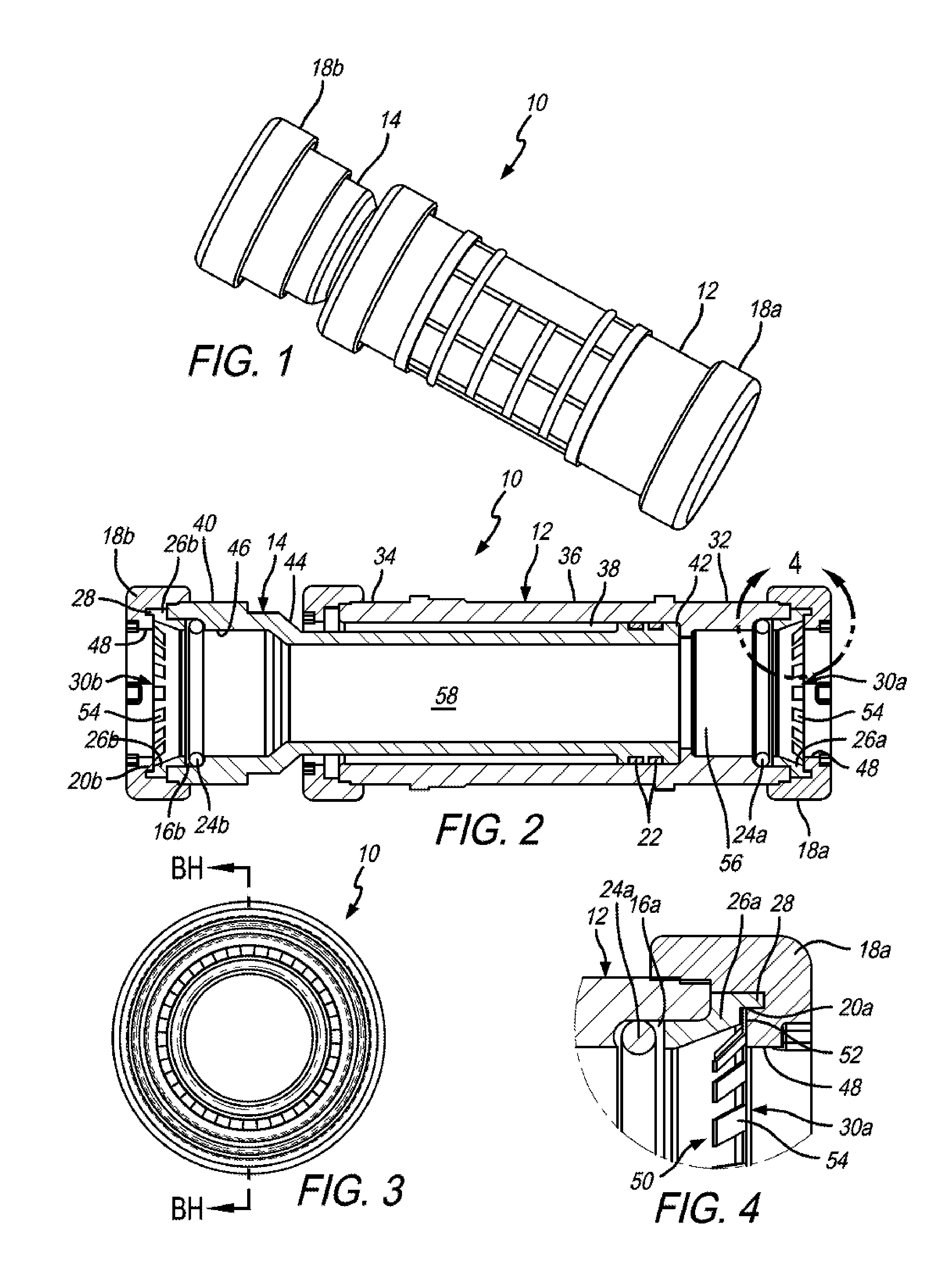
The present Application claims the benefit of U.S. Provisional Patent Application No. 62/075,996 titled “Telescoping Pipe Coupling,” filed Nov. 6, 2014, the contents of which are incorporated in this disclosure by reference in their entirety. Telescoping pipe couplings for joining two sections of pipe are well known. Telescoping pipe couplings are used to join together two separate pipe sections, either during the initial construction of a piping system or in the maintenance of an existing piping system. Telescoping pipe couplings are most commonly used in the repair of PVC and other plastic pipes. Telescoping pipe couplings are made with (i) an elongated, hollow body having a smooth bore and (ii) an interior tube slidably disposed in telescoping fashion within the smooth bore. The interior surface of the body is typically lubricated to facilitate axial movement. One or more O-rings or other suitable gaskets are disposed around the circumference of the interior tube to seal the interior tube to the interior surface of the body, while allowing axial movement of the interior tube back and forth within the body. During installation, each pipe section is attached to one of the two open ends of the telescoping pipe coupling with adhesives or by welding techniques. Thus, the attachment of the pipe sections to the telescoping pipe coupling requires considerable time and effort. This is especially a problem when a telescoping pipe coupling is used to repair a leaking or damaged pipe system and time is of the essence. Accordingly, there is a need for an improved telescoping pipe coupling which avoids this problem in the prior art. The present invention satisfies this need. In an embodiment of the present invention, there is provided a telescoping pipe coupling comprising a) a hollow body comprising a first open end, a second open end, an exterior surface and an interior surface; b) a hollow tubular insert slidably disposed within the body, the hollow tubular insert comprising a first open end, a second open end, an exterior surface and an interior surface; c) a first gasket well defined within the internal surface of the first open end of the hollow body; d) a second gasket well defined within the internal surface of the first open end of the hollow tubular insert; e) a first end connector coupled to the first open end of the hollow body, the first end connector comprising an internal surface; f) a second end connector coupled to the first open end of the hollow tubular insert, the second end connector comprising an internal surface; g) a first gripper washer well defined within the internal surface of the first end connector; h) a second gripper washer well defined within the internal surface of the second end connector; i) a first gasket disposed around the exterior surface of the hollow tubular insert for sealing the exterior surface of the hollow tubular insert with the interior surface of the hollow body; j) a second gasket disposed within the first gasket well for sealing an exterior surface of one or more pipe sections to the hollow body; k) a third gasket disposed within the second gasket well for sealing an exterior surface of one or more pipe sections to the hollow tubular insert; l) a first gasket retaining ring disposed between the first end connector and the second gasket for retaining the second gasket within the first gasket well, the first gasket retaining ring comprising a first shoulder; m) a second gasket retaining ring disposed between the second end connector and the third gasket for retaining the third gasket within the second gasket well, the second gasket retaining ring comprising a second shoulder; n) a first gripper washer retained within the first gripper washer well, the first gripper washer comprising an outer periphery; and o) a second gripper washer retained within the second gripper washer well, the second gripper washer comprising an outer periphery; wherein the outer periphery of the first gripper washer is adjacent to the first shoulder of the first gasket retaining ring and the outer periphery of the second gripper washer is adjacent to the second shoulder of the second gasket retaining ring. In another embodiment of the present invention, there is provide a method of using a telescoping pipe coupling, wherein the method comprises the steps of: a) providing the telescoping pipe coupling according to the present invention; b) inserting an end of first pipe section into the first open end of the hollow body; and c) inserting an end of a second pipe section into the first open end of the hollow tubular insert. Features, aspects and advantages of the present invention will become better understood with reference to the following description, appended claims, and accompanying drawings where: The following discussion describes in detail one embodiment of the invention and several variations of that embodiment. This discussion should not be construed, however, as limiting the invention to those particular embodiments. Practitioners skilled in the art will recognize numerous other embodiments as well. Definitions As used herein, the following terms and variations thereof have the meanings given below, unless a different meaning is clearly intended by the context in which such term is used. The terms “a,” “an,” and “the” and similar referents used herein are to be construed to cover both the singular and the plural unless their usage in context indicates otherwise. As used in this disclosure, the term “comprise” and variations of the term, such as “comprising” and “comprises,” are not intended to exclude other additives, components, integers, ingredients or steps. The Invention The invention is a telescoping pipe coupling 10 suitable for joining a first pipe section (not shown) in fluid tight communication with a second pipe section (not shown). The telescoping pipe coupling 10 comprises a hollow body 12, a hollow tubular insert 14, a first gasket well 16 The hollow body 12 can be any size and dimension, and made from any material, including but not limited to plastic, polyvinyl chloride, rubber or metal. The cross-section of the hollow body 12 can be any shape, but preferably the cross-section of the hollow body 12 is circular and the hollow body 12 is cylindrical. The hollow body 12 has a first open end 32, a second open end 34, an exterior surface 36 and an interior surface 38. The hollow body 12 defines a linear passageway 56 between the first open end 32 of the hollow body 12 and the second open end 34 of the hollow body 12. The linear passageway 56 typically has a circular interior diameter. The hollow tubular insert 14 is slidably disposed within the hollow body 12. The hollow tubular insert 14 can be any size and dimension, and made from any material, including but not limited to plastic, polyvinyl chloride, rubber or metal. The hollow tubular insert 14 has a first open end 40, a second open end 42, an exterior surface 44 and an interior surface 46. The hollow tubular insert 14 defines a linear passageway 58 between the first open end 40 of the hollow tubular insert 14 and the second open end 42 of the hollow tubular insert 14. The hollow tubular insert 14 is disposed within the hollow body 12 such that a fluid entering the telescoping pipe coupling 10 via the first open end 32 of the hollow body 12 can flow to the hollow tubular insert 14 via the second open end 42 of hollow tubular insert 14, flow through the hollow tubular insert 14 and exit the telescoping pipe coupling 10 via the first open end 40 of the hollow tubular insert 14. The first and second end connectors 18 The first gasket 22 seals the exterior surface 44 of the hollow tubular insert 14 with the interior surface 38 of the hollow body 12, and typically comprises one or more O-rings or other suitable gaskets disposed around the exterior surface 44 of the hollow tubular insert 14. The second and third gaskets 24 The first, second and third gaskets 22, 24 In the embodiment illustrated in the drawings, the first gripper washer 30 Typically, the gripper washer 30 The shoulders 28 of the first and second gasket retaining rings 26 The inner periphery 50 of the first and second gripper washers 30 Optionally, there can be more than two gripper washers 30 It can be appreciated, therefore, that the telescoping pipe coupling 10 of the invention efficiently and effectively avoids the aforementioned problems inherent in prior art telescoping pipe couplers. Using the telescoping pipe coupling 10 of the invention, the attachment of pipe sections to opposite ends of the telescoping pipe coupling 10 of the invention is quickly and easily accomplished—by merely slipping an open end of the telescoping pipe coupling 10 over an end of a pipe section. No time and effort need be expended in firmly attaching the telescoping pipe coupling 10 to each pipe section end with adhesives or welding procedures. Having thus described the invention, it should be apparent that numerous structural modifications and adaptations may be resorted to without departing from the scope and fair meaning of the instant invention as set forth herein above and described herein below by the claims. A telescoping pipe coupling comprising a hollow body, a hollow tubular insert slidably disposed within the body, two gasket wells, two end connectors, one end connector coupled to each end of the telescoping pipe coupling, two gripper washer wells, a gasket for sealing the tubular insert with the body, two gaskets for sealing one or more pipe sections to the telescoping pipe coupling, two gasket retaining rings each comprising a shoulder, two gripper washers retained within the two gripper washer wells each comprising an outer periphery, wherein the shoulder of each gasket retaining ring is adjacent to the outer periphery of a gripper washer. 1. A telescoping pipe coupling comprising:
a) a hollow body comprising a first open end, a second open end, an exterior surface and an interior surface; b) a hollow tubular insert slidably disposed within the body, the hollow tubular insert comprising a first open end, a second open end, an exterior surface and an interior surface; c) a first gasket well defined within the internal surface of the first open end of the hollow body; d) a second gasket well defined within the internal surface of the first open end of the hollow tubular insert; e) a first end connector coupled to the first open end of the hollow body, the first end connector comprising an internal surface; f) a second end connector coupled to the first open end of the hollow tubular insert, the second end connector comprising an internal surface; g) a first gripper washer well defined within the internal surface of the first end connector; h) a second gripper washer well defined within the internal surface of the second end connector; i) a first gasket disposed around the exterior surface of the hollow tubular insert for sealing the exterior surface of the hollow tubular insert with the interior surface of the hollow body; j) a second gasket disposed within the first gasket well for sealing an exterior surface of one or more pipe sections to the hollow body; k) a third gasket disposed within the second gasket well for sealing an exterior surface of one or more pipe sections to the hollow tubular insert; l) a first gasket retaining ring disposed between the first end connector and the second gasket for retaining the second gasket within the first gasket well, the first gasket retaining ring comprising a first shoulder; m) a second gasket retaining ring disposed between the second end connector and the third gasket for retaining the third gasket within the second gasket well, the second gasket retaining ring comprising a second shoulder; n) a first gripper washer retained within the first gripper washer well, the first gripper washer comprising an outer periphery; and o) a second gripper washer retained within the second gripper washer well, the second gripper washer comprising an outer periphery; wherein the outer periphery of the first gripper washer is adjacent to the first shoulder of the first gasket retaining ring and the outer periphery of the second gripper washer is adjacent to the second shoulder of the second gasket retaining ring. 2. The telescoping pipe coupling according to 3. The telescoping pipe coupling according to 4. The telescoping pipe coupling according to 5. The telescoping pipe coupling according to 6. The telescoping pipe coupling according to 7. The telescoping pipe coupling according to 8. The telescoping pipe coupling according to 9. The telescoping pipe coupling according to 10. A method of using a telescoping pipe coupling, the method comprising the steps of:
a) providing the telescoping pipe coupling according to b) inserting an end of first pipe section into the first open end of the hollow body; and c) inserting an end of a second pipe section into the first open end of the hollow tubular insert. 11. The method of 12. The method of 13. The method of 14. The method of 15. The method of 16. The method of 17. The method of CROSS-REFERENCE TO RELATED APPLICATIONS
BACKGROUND OF THE INVENTION
SUMMARY OF THE INVENTION
DRAWINGS
DETAILED DESCRIPTION OF THE INVENTION