ROBOT
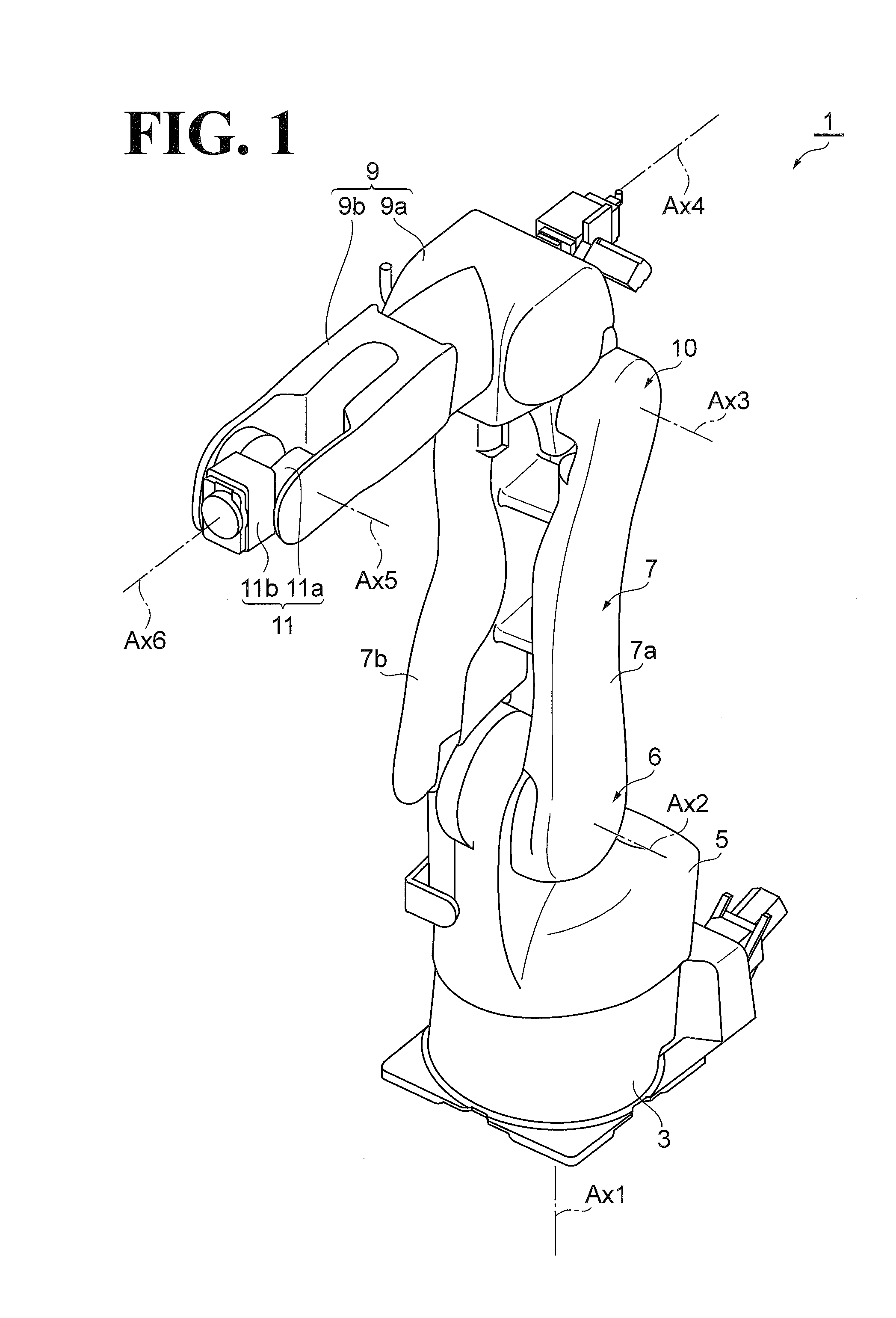
The present application claims priority under 35 U.S.C. §119 to Japanese Patent Application No. 2015-015703, filed Jan. 29, 2015. The contents of this application are incorporated herein by reference in their entirety. 1. Field of the Invention The embodiments disclosed herein relate to a robot. 2. Discussion of the Background Japanese Unexamined Patent Application Publication No. 2003-200376 discloses an industrial robot that includes a base, a turnable portion, a lower arm, and an upper arm. The turnable portion turns about an S axis relative to the base. The lower arm swings about an L axis relative to the turnable portion. The upper arm swings about a U axis relative to the lower arm. The lower arm operates by a motor that is coaxial with the L axis, and the upper arm operates by a motor that is coaxial with the U axis. According to one aspect of the present disclosure, a robot includes a base, a first arm, a second arm, a first motor, and a second motor. The first arm is disposed on the base and swingable about a first axis parallel to an installation surface on which the base is installed. The second arm is disposed on the first arm and swingable about a second axis parallel to the first axis. The first motor is configured to move the first arm about the first axis relative to the base. The first motor includes a first body and a first protrusion. The first body has an axial dimension in a direction along an output shaft of the first motor and a perpendicular dimension in a direction approximately perpendicular to the output shaft of the first motor. The axial dimension is smaller than the perpendicular dimension. The first protrusion protrudes from a surface of the first body in a direction along the output shaft of the first motor and is disposed at a position displaced from the output shaft of the first motor. The second motor is configured to move the second arm about the second axis relative to the first arm. The second motor includes a second body and a second protrusion. The second body has an axial dimension in a direction along an output shaft of the second motor and a perpendicular dimension in a direction approximately perpendicular to the output shaft of the second motor. The axial dimension is smaller than the perpendicular dimension. The second protrusion protrudes from a surface of the second body in a direction along the output shaft of the second motor and is disposed at a position displaced from the output shaft of the second motor. A more complete appreciation of the present disclosure and many of the attendant advantages thereof will be readily obtained as the same becomes better understood by reference to the following detailed description when considered in connection with the accompanying drawings, wherein: The embodiments will now be described with reference to the accompanying drawings, wherein like reference numerals designate corresponding or identical elements throughout the various drawings. As illustrated in The base 3 is fixed to an installation surface and supports the entire robot 1. The turnable portion 5 is disposed on the base 3. The turnable portion 5 is turnable about a turning axis, namely, a first axis Ax1, which extends in the vertical direction, relative to the base 3. The turnable portion 5 is driven into turning operation about the first axis Ax1 by a power source, namely, a first motor (not illustrated), which is accommodated in the turnable portion 5. The first axis Ax1 will be occasionally referred to as “S axis”. The first arm 7 is swingable about a swing axis, namely, a second axis Ax2 (corresponding to the first axis recited in the appended claims) relative to the turnable portion 5. The second axis Ax2 passes through a connection portion 6 (the end of the first arm 7 on the side of the turnable portion 5), at which the turnable portion 5 and the first arm 7 are coupled to each other. The first arm 7 includes a first arm member 7 The first arm 7 is driven by a power source, namely, the second motor M2, into swing operation about the second axis Ax2. Specifically, as illustrated in The second arm 9 includes a base end 9 The second arm 9 (base end 9 The distal end 9 The end base 11 includes a base end 11 The distal end 11 Next, the first to sixth motors provided in the robot 1 will be described in detail. The first to sixth motors have similar configurations and may hereinafter occasionally be referred to as “motor 20” collectively. The casing 30 holds elements such as the rotor 40, the stator 50, and the encoder 60. In this embodiment, the casing 30 has a circular outer shape. The casing 30 includes a first surface 30 The rotor 40 includes a rotator 42 and a brake pad 44. The rotator 42 is a member that can be driven into rotation about the output shaft Ax. The rotator 42 is rotatable by ring-shaped bearings 46 The brake pad 44 is a member that performs braking operation as controlled by the brake 70. The brake pad 44 is disposed over the circumference of the rotator 42. The brake pad 44 has a ring shape. The brake pad 44 is coaxial with the output shaft Ax. The outer edge of the brake pad 44 is further outward than the outer edge of the rotator 42. That is, the outer diameter of the brake pad 44 is larger than the outer diameter of the rotator 42. In this embodiment, the brake pad 44 is made of metal. The stator 50 is a member that imparts rotational force to the rotor 40. The stator 50 includes a core 52 and a coil 54. In this embodiment, the core 52 has a ring shape. The core 52 faces the outer surface of the rotator 42. The coil 54 is disposed on the core 52. The encoder 60 is a rotation detector that detects the rotation of the rotor 40. A non-limiting example of the encoder 60 is a rotary encoder capable of detecting amounts by which the motor 20 is driven, such as the number of rotations of the rotor 40, the rotational angle of the rotor 40, and/or the rotational speed of the rotor 40. The encoder 60 is partially disposed in a depression 42 The brake 70 is a braking device that causes the rotating rotor 40 to brake. The brake 70 protrudes outward from the second surface 30 The case 72 accommodates the holding member 76, the biasing member 78, and the coil 79. In this embodiment, the case 72 is fixed to the casing 30 with a screw. In the embodiment illustrated in The friction material 74 comes into sliding contact with the brake pad 44 of the rotor 40 to impart frictional force to the brake pad 44. The friction material 74 is disposed on the holding member 76. Examples of the material of the friction material 74 include, but are not limited to, resin mold, semi-metallic material, and sintered alloy (of iron and/or copper). The holding member 76 holds the friction material 74. In this embodiment, the holding member 76 is made of metal. The holding member 76 has an approximately T shape. The holding member 76 includes a body 76 In this embodiment, the body 76 The holding member 76 is movable (sliding-movable) in the direction along the output shaft Ax. Specifically, the holding member 76 is movable between a first position (initial position) and a second position. At the first position, the holder 76 The biasing member 78 biases the holding member 76. In this embodiment, the biasing member 78 is a coil spring. The biasing member 78 is disposed on the other end of the body 76 The coil 79 regulates the movement of the holding member 76. The coil 79 surrounds the body 76 When supply of current through the coil 79 is discontinued, the brake 70 with the above-described configuration causes the coil 79 to release the holding member 76, and allows the biasing force of the biasing member 78 to move the holding member 76 toward the rotor 40. That is, the brake 70 positions the holding member 76 at the second position. Then, the brake 70 causes the friction material 74 to sliding-contact the brake pad 44 to impart frictional force to the brake pad 44. This configuration causes the rotating rotor 40 to decelerate or stop and prevents the stationary rotor 40 from rotating. When current is supplied through the coil 79, the brake 70 causes the coil 79 to pull the holding member 76 to separate the friction material 74 and the brake pad 44 from each other. That is, the brake 70 positions the holding member 76 at the first position. This configuration makes the rotor 40 rotatable. Next, arrangement of the motor 20 (second motor M2, third motor M3) with the above-described configuration will be described. The second motor M2 is disposed at the connection portion 6, at which the turnable portion 5 and the first arm 7 are coupled to each other. The second motor M2 is disposed on the second arm member 7 The second motor M2 is coupled to a reducer (first reducer) 15. The reducer 15 is disposed on the first arm member 7 With the second motor M2 fixed to the turnable portion 5, the brake 70 of the second motor M2 is at a particular position. Specifically, as illustrated in In a view from the direction along the second axis Ax2, the cable C overlaps the casing 30 of the second motor M2 with the second surface 30 The third motor M3 is disposed at the connection portion 10, at which the first arm 7 and the second arm 9 are coupled to each other. The third motor M3 is fixed to the second arm 9. Specifically, the output shaft Ax of the third motor M3 is coaxial with the third axis Ax3. The third motor M3 is coupled to a reducer (second reducer) 17. The reducer 17 is disposed on the side of the first arm member 7 With the third motor M3 fixed to the second arm 9, the brake 70 of the third motor M3 is at a particular position. Specifically, as illustrated in In a view from the direction along the third axis Ax3, the cable C overlaps the casing 30 of the third motor M3 with the second surface 30 As has been described hereinbefore, in the robot 1 according to this embodiment, the casing 30 of the motor 20 has a smaller axial dimension, which is in the direction along the output shaft Ax, than the perpendicular dimension of the casing 30 in the direction approximately perpendicular to the output shaft Ax. That is, the casing 30 has a flat shape. Thus, the casing 30 is flat and the motor 20 is disposed with its output shaft Ax parallel to the swing axis. This configuration decreases the dimension of the motor 20 in the width direction (L1). Here, motors used in conventional robots have larger dimensions in the axial direction because the motor section and the brake section are coaxial with each other. If such motor is used in a robot, it is necessary to circumvent the motor in the work of wiring the cable along the arm to the motor and other elements. That is, the cable is wired along the side of the arm opposite to the side on which the motor is disposed. This configuration involves addition of the width dimension of the motor and the width dimension of cable to the width dimension of the arm. As a result, the width dimension of the arm as a whole increases. The brake 70 of the motor 20 according to this embodiment protrudes from the second surface 30 In this embodiment, the cable C overlaps the casing 30 of the second motor M2 in a view from the direction along the second axis Ax2, and overlaps the casing 30 of the third motor M3 in a view from the direction along the third axis Ax3. Here, the second surface 30 In this embodiment, the robot 1 includes the reducer 15 and the reducer 17. The reducer 15 is coupled to the second motor M2 and has an input shaft coaxial with the output shaft Ax. The reducer 17 is coupled to the third motor M3 and has an input shaft coaxial with the output shaft Ax. The second motor M2 is disposed between the reducer 15 and the cable C in the direction along the second axis Ax2. The third motor M3 is disposed between the reducer 17 and the cable C in the direction along the third axis Ax3. Thus, the motors M2 and M3 are disposed between the cable C and the respective reducers 15 and 17 in the respective axial directions. This configuration decreases the width dimensions of the first arm 7 and the second arm 9 even though the reducers 15 and 17 are coaxial with the motor 20. In this embodiment, the second motor M2 is fixed to the turnable portion 5. Since the second motor M2 is fixed to the turnable portion 5, the second motor M2 itself does not turn relative to the turnable portion 5. Specifically, the second motor M2 is fixed with the brake 70 positioned to prevent the first arm 7 from taking an abnormal posture (such as involving forcible stretch of the cable C) when the first arm 7 swings and the cable C contacts the brake 70. This configuration eliminates or minimizes excessive contact between the cable C and the brake 70, and eliminates or minimizes resulting degradation, damage, and other similar occurrences to the cable C. The third motor M3 is fixed to the second arm 9. Since the third motor M3 is fixed to the second arm 9, the third motor M3 turns together with the second arm 9. Specifically, the third motor M3 is fixed with the brake 70 positioned to prevent the second arm 9 from taking an abnormal posture when the second arm 9 swings and the cable C contacts the brake 70. In this embodiment, the output shaft Ax of the second motor M2 and the second axis Ax2 are coaxial with each other. The first arm 7 is swingable in the first direction D1 up to the first swing angle θ1 relative to the first reference line LS1, which is in the direction approximately perpendicular to the installation surface and which passes through the second axis Ax2. The first arm 7 is also swingable relative to the first reference line LS1 in the second direction D2, which is opposite to the first direction D1, up to the second swing angle θ2, which is smaller than the first swing angle θ1. In a view from the direction along the second axis Ax2, the brake 70 of the second motor M2 is disposed at a position that is lower than the second axis Ax2 in the direction toward the installation surface and that is further in the second direction D2 than the first reference line LS1. This configuration ensures that as illustrated in In this embodiment, the output shaft Ax of the third motor M3 and the third axis Ax3 are coaxial with each other. The second arm 9 is swingable in the first direction D1 up to the first swing angle θ3 relative to the second reference line LS2, which is in the direction approximately perpendicular to the installation surface and which passes through the third axis Ax3. The second arm 9 is also swingable relative to the second reference line LS2 in the second direction D2, which is opposite to the first direction D1, up to the second swing angle θ4, which is smaller than the first swing angle θ3. While the second arm 9 is not swinging relative to the second reference line LS2, the brake 70 of the third motor M3 is at a position that is further away from the second axis Ax2 than the third axis Ax3 is from the second axis Ax2 in a view from the direction along the third axis Ax3. This configuration ensures that as illustrated in In this embodiment, the cable C is fixed with the fixtures F1 to F4. The fixtures F1 and F2 are disposed across the second motor M2, and the fixtures F3 and F4 are disposed across the third motor M3. Arranging the fixtures F1 to F4 in this manner prevents the cable C from coming loose due to the swing of the first arm 7 and the second arm 9. Preventing the cable C from coming loose eliminates or minimizes contact between the cable C and workpieces. It is noted that this arrangement of the fixtures F1 to F4 is not essential. Another possible embodiment is to omit the fixtures F2 and F3 and arrange the fixture F1 and the fixture F4 across the second motor M2 and the third motor M3. It is also noted that the fixtures may not necessarily fix the cable C completely, but may be turnable metal fittings, turnable cable guides, or any other turnable fixtures. The above-described embodiment should not be construed in a limiting sense. For example, while the above-described embodiment has been described as including the first arm 7 and the second arm 9, an additional arm may be coupled to the second arm 9. While in the above-described embodiment the motor 20 has been described as having the configuration illustrated in Obviously, numerous modifications and variations of the present disclosure are possible in light of the above teachings. It is therefore to be understood that within the scope of the appended claims, the present disclosure may be practiced otherwise than as specifically described herein. A robot includes a base, a first arm, a second arm, a first motor, and a second motor. The first arm is disposed on the base and swingable about a first axis. The second arm is disposed on the first arm and swingable about a second axis. The first motor moves the first arm about the first axis. The second motor moves the second arm about the second axis. The first and second motors each include a body and a protrusion. The body has an axial dimension in a direction along an output shaft of each motor and a perpendicular dimension in a direction approximately perpendicular to the output shaft. The axial dimension is smaller than the perpendicular dimension. The protrusion protrudes from a surface of the body in a direction along the output shaft and is disposed at a position displaced from the output shaft. 1. A robot comprising:
a base; a first arm disposed on the base and swingable about a first axis parallel to an installation surface on which the base is installed; a second arm disposed on the first arm and swingable about a second axis parallel to the first axis; a first motor configured to move the first arm about the first axis relative to the base, the first motor comprising:
a first body comprising an axial dimension in a direction along an output shaft of the first motor and a perpendicular dimension in a direction approximately perpendicular to the output shaft of the first motor, the axial dimension being smaller than the perpendicular dimension; and a first protrusion protruding from a surface of the first body in a direction along the output shaft of the first motor and disposed at a position displaced from the output shaft of the first motor; and a second motor configured to move the second arm about the second axis relative to the first arm, the second motor comprising:
a second body comprising an axial dimension in a direction along an output shaft of the second motor and a perpendicular dimension in a direction approximately perpendicular to the output shaft of the second motor, the axial dimension being smaller than the perpendicular dimension; and a second protrusion protruding from a surface of the second body in a direction along the output shaft of the second motor and disposed at a position displaced from the output shaft of the second motor. 2. The robot according to 3. The robot according to a first reducer coupled to the first motor and comprising an input shaft coaxial with the output shaft of the first motor, wherein the first motor is disposed between the first reducer and the cable in a direction along the first axis; and a second reducer coupled to the second motor and comprising an input shaft coaxial with the output shaft of the second motor, wherein the second motor is disposed between the second reducer and the cable in a direction along the second axis. 4. The robot according to wherein the first motor is fixed to the base, and wherein the second motor is fixed to the second arm. 5. The robot according to wherein the output shaft of the first motor and the first axis are coaxial with each other, wherein the first arm is swingable in a first direction up to a first swing angle relative to a first reference line that is in a direction approximately perpendicular to the installation surface and that passes through the first axis, and the first arm is swingable relative to the first reference line in a second direction opposite to the first direction up to a second swing angle smaller than the first swing angle, and wherein in a view from a direction along the first axis, the first protrusion of the first motor is disposed at a position that is lower than the first axis in a direction toward the installation surface and that is further in the second direction than the first reference line. 6. The robot according to wherein the output shaft of the second motor and the second axis are coaxial with each other, wherein the second arm is swingable in a first direction up to a first swing angle relative to a second reference line that is in a direction approximately perpendicular to the installation surface and that passes through the second axis, and the second arm is swingable relative to the second reference line in a second direction opposite to the first direction up to a second swing angle smaller than the first swing angle, and wherein while the second arm is not swinging relative to the second reference line, the second protrusion of the second arm is at a position that is further away from the first axis than the second axis is from the first axis in a view from a direction along the second axis. 7. The robot according to 8. The robot according to 9. The robot according to 10. The robot according to wherein the first motor is fixed to the base, and wherein the second motor is fixed to the second arm. 11. The robot according to wherein the output shaft of the first motor and the first axis are coaxial with each other, wherein the first arm is swingable in a first direction up to a first swing angle relative to a first reference line that is in a direction approximately perpendicular to the installation surface and that passes through the first axis, and the first arm is swingable relative to the first reference line in a second direction opposite to the first direction up to a second swing angle smaller than the first swing angle, and wherein in a view from a direction along the first axis, the first protrusion of the first motor is disposed at a position that is lower than the first axis in a direction toward the installation surface and that is further in the second direction than the first reference line. 12. The robot according to wherein the output shaft of the second motor and the second axis are coaxial with each other, wherein the second arm is swingable in a first direction up to a first swing angle relative to a second reference line that is in a direction approximately perpendicular to the installation surface and that passes through the second axis, and the second arm is swingable relative to the second reference line in a second direction opposite to the first direction up to a second swing angle smaller than the first swing angle, and wherein while the second arm is not swinging relative to the second reference line, the second protrusion of the second arm is at a position that is further away from the first axis than the second axis is from the first axis in a view from a direction along the second axis. 13. The robot according to 14. The robot according to 15. The robot according to 16. The robot according to 17. The robot according to 18. The robot according to 19. The robot according to 20. The robot according to CROSS-REFERENCE TO RELATED APPLICATIONS
BACKGROUND
SUMMARY
BRIEF DESCRIPTION OF THE DRAWINGS
DESCRIPTION OF THE EMBODIMENTS
Configuration of Robot
Configurations of Motors
Motor Arrangement
Advantageous Effects