Injection Site Information Cap
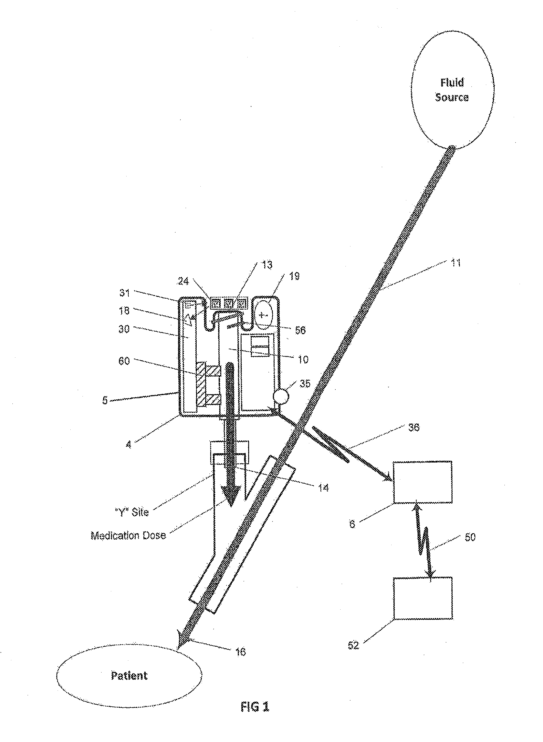
This application is a continuation application of U.S. Utility patent application Ser. No. 13/802,231 filed Mar. 13, 2013, the entire disclosure of which is herein incorporated by reference. The subject matter described herein relates to an injection site information cap and method for use in providing information to recordkeeping systems to automatically document caregiver identification, patient care activity, and/or procedural steps in the use of and/or care of a medication injection site. Many health care procedures involve IV medication administrations. The type of medication and timing of administration are important to record in order to provide healthcare providers real-time information on the conduct of the procedure and the completion of a medical record. Some protocols require quick medication administrations with limited time for documentation and record keeping. Others require completion and verification of medication administration manually to ensure proper patient care and accounting for use of medications. Injectable medications and fluids are frequently utilized by healthcare providers (caregivers) in the care of patients in the hospital, in pre-hospital emergency medical services (EMS) and at alternate care sites (including skilled nursing facilities, home health and hospice settings). Caregivers can include medical doctors, registered nurses, EMS paramedics, dentists and other licensed healthcare practitioners. Accurate documentation of what, when and how much medication and/or IV fluid is given to a patient is required by healthcare institutions, governmental agencies and regulatory oversight agencies. This is especially true when the IV fluid being administered to the patient is a medication or blood product. The type of IV fluid and the timing of administration are important to record in order to provide healthcare providers real-time information on the conduct of the procedure and the completion of a medical record. Some protocols require quick IV fluid administrations with limited time for documentation and record keeping. Others require completion and verification of manually administered IV fluids to ensure proper patient care and accounting for use of IV fluids. Additionally, to ensure proper patient safety and limit exposure to catheter-related bloodstream infections (CRBSI), vascular access ports (injection sites) require careful disinfection and careful management of the patient's IV site for patency. Absent these activities, needleless injection sites can become contaminated and patient vascular access can become infiltrated or blocked. When these situations occur, patient safety is compromised resulting in infection, pain, longer hospital stays and even death. Hospital costs for continued patient care increase and are not reimbursed by third party payers. New automated documentation systems for medication administrations will likely help in the tracking of medication injections, but none have addressed the documentation of proper IV site care and the management of needleless injection sites for infection control or IV site for patency. Manual use of alcohol swabs or sterile caps containing a disinfectant solution are gaining popularity for disinfecting IV injection sites and controlling CRBSI. When caps are left attached to IV luer access needless valves they can disinfect and protect the IV site. To date, these activities are often not documented, rarely time tracked and even less likely to be identified by caregiver. Other patient care activity and procedural steps such as obtaining lab samples, assisting in respiratory therapy, dietary management also require timely documentation. Manual documentation often results in accuracy errors, missed notations and undocumented activity due to fast paced patient care with limited resources. A better system could result in less error, increased billing accuracy, reduced paperwork and more time for caregivers to focus on patient care. Tracking of who did what and when at the point of care can be improved. In one aspect, an injection site information cap includes a housing, a cover portion, an engagement portion configured to couple to and cover an injection port of an injection site and at least one information element on the cover portion that is positioned to be automatically sensed by at least one sensor of the injection site when the engagement portion is coupled to or is being coupled to the medication injection port. The engagement portion can include a female luer lock thread configured to be coupled to a male luer lock thread on the injection port. The at least one information element can be encoded with one or more of: mechanically encoded information, magnetically encoded information, a near field communication (NFC) tag, and a radio frequency identification (RFID) tag. The at least one information element can include optically encoded information. The optically encoded information can include at least one bar code. The at least one bar code can be sensed by the at least one sensor as the cover portion is circumferentially rotated or translated linearly on the axial centerline of the luer lock. The injection site information cap can include a disinfectant to disinfect the injection port upon the coupling of the engagement portion with the injection port. The engagement portion can be further configured to seal the injection port of the injection site. The injection port can be fluidically coupled to a patient and/or to a fluid wasting reservoir. The information element can encapsulate data characterizing one or more of: a disinfection state of the injection port, a caregiver identification, an identification of a patient, a procedural step performed in connection with care of the patient, a state of waste disposal, a lab sample, respiratory management for the patient, and dietary management for the patient. Some or all of the housing can be color coded with one of a plurality of color categories. Each color category can characterize one or more of: caregiver identification, a patient care procedural activity, a laboratory sample, a state of the injection port, a fluid injected into the injection port, and a state of a patient. The at least one sensor or a different sensor can, in some variations, detect the color. In addition, in some variations, at least the information element is color coded with one of a plurality of color categories, each color category characterizing one or more of: care giver identification, a patient care procedural activity, a laboratory sample, a state of the injection port, a fluid injected into the injection port, and a state of a patient. The information element can be affixed to an outer surface of the cover portion or it can be integral to an outer surface of the cover portion. In a further aspect, an injection site information cap can include multiple engagement portions. For example, a medication injection site can comprise a housing including a first engagement portion on the housing configured to couple to and cover a first injection port of a first injection site. At least one first information element on an outer surface of the first engagement portion of the housing can be positioned to be automatically sensed by at least one first sensor of the first injection site when the first engagement portion is coupled to or is being coupled to the first injection port, a second engagement portion on the housing can be configured to couple to and cover a second injection port of a second injection site, and at least one second information element on an outer surface of the second engagement portion of the housing can be positioned to be automatically sensed by at least one second sensor of the second injection site when the second engagement portion is coupled to or is being coupled to the second injection port. The at least one of the first engagement portion and the second engagement portion can comprises a female luer lock thread configured to couple to a male luer lock thread on the injection port. The at least one first information element and the at least one second information element can be encoded with one or more of: mechanically encoded information, magnetically encoded information, a near field communication (NFC) tag, and a radio frequency identification (RFID) tag. The at least one second information element can be optically encoded information. The optically encoded information can be at least one bar code. The at least one bar code can be sensed by the at least one sensor as the housing is circumferentially rotated. The information cap can further comprise: a disinfectant to disinfect at least one of the first injection port upon the coupling of the first engagement portion to the first injection port. The at least one of the first injection port and the second injection port can be fluidically coupled to a patient. The at least one of the first injection port and the second injection port can be fluidically coupled to a fluid wasting reservoir. The injection site information cap can include one or more of the at least one first information element and the at least one second information element to encapsulate data characterizing one or more of: a disinfection state of the injection port, a caregiver identification, an identification of a patient, a procedural step performed in connection with care of the patient, a state of waste disposal, a lab sample, respiratory management for the patient, and dietary management for the patient. The information cap can include at least a portion of the housing, and/or the information element, to be color coded with one of a plurality of color categories, each color category characterizing one or more of: caregiver identification, a patient care procedural activity, a laboratory sample, a state of the injection port, a fluid injected into the injection port, and a state of a patient. The one or more of the at least one first information element and the at least one second information element can be affixed to an outer surface of the housing. The at least one first information element and the at least one second information element can be integral to an outer surface of the housing. The at least one of the first engagement portion and the second engagement portion can be further configured to seal and/or cover the injection port of the injection site. The first injection site and the second injection site can be physically connected to each other. In some variations, the at least one first information element is different from the at least one second information element while in other variations the elements are the same (identical). Each engagement portion can have identical features such as disinfectant or they can differ (one side has disinfectant while the other does not). The housing can be color coded in different manners similar to a single engagement portion injection cap. The first engagement portion can be positioned opposite the second engagement portion. In other variations, the first engagement portion is positioned at an angle or otherwise askew as compared to a center line of the second engagement portion. In other variations, the housing can be flexible. In a further interrelated aspect, an apparatus includes a first engagement portion on the housing configured to cover a injection port, at least one first information element on an outer surface of the first engagement portion of the housing positioned to be automatically sensed by at least one first sensor of the injection site when the first engagement portion is coupled to or is being coupled to the injection port; a second engagement portion on the housing configured to cover the injection port, and at least one second information element on an outer surface of the second engagement portion of the housing positioned to be automatically sensed by at least one sensor of the injection site when the second engagement portion is coupled to or is being coupled to the injection port. The injection site information caps as described herein can be used in connection with various methods. For example, one method can include receiving information from a medication delivery apparatus characterizing at least one information element on a cap covering an injection port of the medication delivery apparatus, associating the received information with data comprising one or more of: a disinfection state of the injection port, a caregiver identification, an identification of a patient, a procedural step performed in connection with care of the patient, a state of waste disposal, a lab sample, respiratory management for the patient, and dietary management for the patient, and promoting the associated data. The medication delivery apparatus (injection site) can include a housing, a fluid conduit at least partially extending within the housing and configured to deliver medication within a medication container to the patient, an injection port extending from an external surface of the housing and configured to be coupled to a fluid outlet of the medication container (the medication port being fluidically and directly coupled to the fluid conduit), and at least one sensor disposed within the housing to sense the at least one information element on the information cap. In some variations, the medication delivery apparatus can also include a transmitter within the housing to wirelessly transmit information generated by the at least one sensor to a remote data collection system, and a self-contained power source within the housing powering the at least one sensor and the transmitter. Promoting the associated data can include one or more of: displaying the associated data, storing the associated data into a physical storage device, loading the associated data into memory, and transmitting the associated data to a remote computing system. Computer program products are also described that comprise nontransitory computer readable media storing instructions, which when executed one or more data processor of one or more computing systems, causes at least one data processor to perform operations herein. Similarly, computer systems are also described that may include one or more data processors and a memory coupled to the one or more data processors. The memory may temporarily or permanently store instructions that cause at least one processor to perform one or more of the operations described herein. In addition, methods can be implemented by one or more data processors either within a single computing system or distributed among two or more computing systems. Such computing systems can be connected and can exchange data and/or commands or other instructions or the like via one or more connections, including but not limited to a connection over a network (e.g. the Internet, a wireless wide area network, a local area network, a wide area network, a wired network, or the like), via a direct connection between one or more of the multiple computing systems, etc. The subject matter described herein provides many advantages. For example, the current subject matter allows for compact injection port systems that automatically identify activity at the injection site. The fluid injection port is sufficiently small to be placed on a standard IV line (and to be self-supporting) allowing it to be used in multiple situations including on-site paramedic treatments, during ambulance delivery of patients, as well as medical facilities such as emergency rooms/intensive care units/operating rooms/general care. Moreover, as medical staff (e.g., doctors, nurses, paramedics, etc.) are accustomed to handling Y-sites on IV lines and the current subject matter requires little, if any, behavior modifications while allowing for intelligent logging of patient care activities within normal workflow. In addition, the compact nature of the fluid injection port obviates the need for a larger tabletop or cradle bar code unit which can be cumbersome during code blue or other emergency events and which can require much needed space (displacing other required equipment). In addition, the current subject matter utilizes a wireless interface and does not require wires for communication of information to a data collection system which could interfere with or complicate patient care activity. Data received by the data collection system can be actively displayed in real-time providing clearly visible information to the medical staff keeping all informed and up-to-date. Furthermore, the current subject matter reduces manual record keeping and other activities that can tend to detract from the needed attention to a patient. Automated record keeping provides accurate records and frees up the health care provider's time enabling improved patient care. The details of one or more variations of the subject matter described herein are set forth in the accompanying drawings and the description below. Other features and advantages of the subject matter described herein will be apparent from the description and drawings, and from the claims. The accompanying drawings, which are incorporated in and constitute a part of this specification, show certain aspects of the subject matter disclosed herein and, together with the description, help explain some of the principles associated with the disclosed embodiments. In the drawings: Like reference symbols in the various drawings indicate like or similar elements. This application relates to each of the following applications, which are all entitled “Medication Injection Site and Data Collection System”: U.S. patent application Ser. No. 13/777,964 filed Feb. 26, 2013, which is a continuation-in-part of U.S. patent application Ser. No. 13/777,831 filed on Feb. 26, 2013, which in turn is a continuation-in-part of U.S. patent application Ser. No. 12/938,300 filed on Nov. 2, 2010, which in turn is a continuation-in-part of U.S. patent application Ser. No. 12/765,707 filed on Apr. 22, 2010, which in turn is a continuation-in-part of U.S. patent application Ser. No. 12/614,276 filed on Nov. 6, 2009; and additionally, priority is also claimed to U.S. Pat. App. Ser. No. 61/370,974 filed on Aug. 5, 2010. Each of the aforementioned patent applications are hereby fully incorporated by reference. Additionally, this application relates to each of the following applications, which are entitled “Medication Container Encoding, Verification, and Identification”: U.S. patent application Ser. No. 13/671,752 filed Nov. 8, 2012, which is a continuation-in-part of U.S. patent application Ser. No. 13/149,782 filed on May 31, 2011. Each of the aforementioned patent applications are hereby fully incorporated by reference. In addition to system 3 for encoded medication containers as shown in Information cap 200 can be colored to designate a category. The color can be part of housing 5, part of information element 24 (background color) or part of data element 12. Categories can include any assigned color or type. For example color assignments could be: red=lab sample taken, orange=caregiver ID, yellow=medication given, green=billing charge, blue=physical therapy activity, violet=lab sample taken, white=sedation activity. Other colors and/or categories can be included. The color can be detected by identification sensor 18 and transmitted to the data collection system in addition to the information contained in the information element. The information can be detected by identification sensor 18 when a specific wavelength light (ultraviolet, infrared, etc), a specific RF or magnetic frequency, or a combination of frequency and wavelength is emitted from emitter 31. Information cap 200 can be used with intelligent injection site 4 for caregiver identification during medication waste disposal. In this use case, intelligent injection site 4 can be connected to a medication waste disposal receptacle. Information cap 200 can contain caregiver ID information and document who and when medication waste is disposed. This can be followed by an encoded medication container and injection of waste medication into the receptacle. Fluid delivery sensor 60 can measure the volume of waste disposed. A second caregiver can verify waste disposal by immediately following waste disposal with the attachment of a second information cap 200 having a different caregiver ID. Information detected on caregivers information caps 200 and encoded medication container waste disposed volume can be transmitted 36 to data collection system 6, time stamped and transmitted 50 to medical information system 52. Information element 24 on information cap 200 can be any one or more of: mechanically encoded information, magnetically encoded information, a near field communication (NFC) tag, a radio frequency readable information (RFID tag). The information element 24 can also or alternatively comprise optically encoded information and the identification sensor 18 can comprise an optical emitter and an optical detector to read the optically encoded information. The identification sensor 18 can include an optical emitter LED to illuminate the information element 24 and an optical detector such as a camera (charge coupled device—CCD). The identification sensor 18 can read information from the information element 24 as a result of relative motion of the information cap relative to injection site 4. The identification sensor 18 can read information from the information element 24 in response to mechanically coupling the information cap 200 to the injection site 4. Information cap 200 can carry an information element 24 that provides detectable information indicative of an activity performed by a caregiver or a patient. The activity can be any one or more of: disinfection of the injection site, caregiver identification (name, ID number, employee number), a procedural step performed (IV site visual assessment, a surgical procedure step, an intensive care unit activity, an emergency medical services {EMS} activity), confirmation of waste disposal (unused controlled substances, contaminated waste, etc.), other patient care activity such as obtaining a lab sample from a patient, assisting in respiratory therapy of a patient, dietary management of a patient, and many other patient care activities at home, in the field, or in a hospital environment where recordation is appropriate. The data encapsulated by element 24 can be detected by an intelligent injection site and processed either locally or by transmitting to a remote computing system. The identification sensor 18 can include an optical emitter/detector pair 31 that detects encoded information contained on information element 24 (a sleeve or label wrapped around injection site information cap 100). The identification sensor 18 can comprise a plurality of sensors to detect information element 24. In some variations, the identification sensors can be sensors such as optical, magnetic, mechanical, conductive, switchable RFID and/or proximity sensors. In other variations, identification sensor 18 can be optical and can include an illumination source (emitter) such as an LED and a detection source (detector) such as a camera (CCD). Sensor circuit 30 can provide signal processing and connects identification sensor 18 to transmitter 34. The identification sensor 18 can be directly coupled to power source 19. Aspects of the subject matter described herein can be embodied in systems, apparatus, kits (e.g., kits with the medication injection site being enclosed therein), methods, and/or articles depending on the desired configuration. In particular, aspects of the subject matter described herein can be realized in digital electronic circuitry, integrated circuitry, specially designed ASICs (application specific integrated circuits), computer hardware, firmware, software, and/or combinations thereof. These various implementations can include implementation in one or more computer programs that are executable and/or interpretable on a programmable system including at least one programmable processor, which can be special or general purpose, coupled to receive data and instructions from, and to transmit data and instructions to, a storage system, at least one input device, and at least one output device. These computer programs, which can also be referred to programs, software, software applications, applications, components, or code, include machine instructions for a programmable processor, and can be implemented in a high-level procedural language, an object-oriented programming language, a functional programming language, a logical programming language, and/or in assembly/machine language. As used herein, the term “machine-readable medium” refers to any computer program product, apparatus and/or device, such as for example magnetic discs, optical disks, memory, and Programmable Logic Devices (PLDs), used to provide machine instructions and/or data to a programmable processor, including a machine-readable medium that receives machine instructions as a machine-readable signal. The term “machine-readable signal” refers to any signal used to provide machine instructions and/or data to a programmable processor. The machine-readable medium can store such machine instructions non-transitorily, such as for example as would a non-transient solid state memory or a magnetic hard drive or any equivalent storage medium. The machine-readable medium can alternatively or additionally store such machine instructions in a transient manner, such as for example as would a processor cache or other random access memory associated with one or more physical processor cores. To provide for interaction with a user, the subject matter described herein can be implemented on a computer having a display device, such as for example a cathode ray tube (CRT) or a liquid crystal display (LCD) monitor for displaying information to the user and a keyboard and a pointing device, such as for example a mouse or a trackball, by which the user may provide input to the computer. Other kinds of devices can be used to provide for interaction with a user as well. For example, feedback provided to the user can be any form of sensory feedback, such as for example visual feedback, auditory feedback, or tactile feedback; and input from the user may be received in any form, including, but not limited to, acoustic, speech, or tactile input. Other possible input devices include, but are not limited to, touch screens or other touch-sensitive devices such as single or multi-point resistive or capacitive trackpads, voice recognition hardware and software, optical scanners, optical pointers, digital image capture devices and associated interpretation software, and the like. The subject matter described herein may be implemented in a computing system that includes a back-end component (e.g., as a data server), or that includes a middleware component (e.g., an application server), or that includes a front-end component (e.g., a client computer having a graphical user interface or a Web browser through which a user may interact with an implementation of the subject matter described herein), or any combination of such back-end, middleware, or front-end components. The components of the system may be interconnected by any form or medium of digital data communication (e.g., a communication network). Examples of communication networks include a local area network (“LAN”), a wide area network (“WAN”), and the Internet. The computing system may include clients and servers. A client and server are generally remote from each other and typically interact through a communication network. The relationship of client and server arises by virtue of computer programs running on the respective computers and having a client-server relationship to each other. The subject matter described herein can be embodied in systems, apparatus, methods, and/or articles depending on the desired configuration. The implementations set forth in the foregoing description do not represent all implementations consistent with the subject matter described herein. Instead, they are merely some examples consistent with aspects related to the described subject matter. Although a few variations have been described in detail above, other modifications or additions are possible. In particular, further features and/or variations can be provided in addition to those set forth herein. For example, the implementations described above can be directed to various combinations and subcombinations of the disclosed features and/or combinations and subcombinations of several further features disclosed above. In addition, the logic flow(s) depicted in the accompanying figures and/or described herein do not necessarily require the particular order shown, or sequential order, to achieve desirable results. Other implementations may be within the scope of the following claims. A injection site information cap includes a housing, a cover portion, an engagement portion configured to couple to and cover an injection port of an injection site, and at least one information element on the cover portion that is positioned to be automatically sensed by at least one sensor of the injection site when the engagement portion is coupled to or is being coupled to the medication injection port. Related apparatus, systems, and techniques are also described. 1. A cap comprising:
an engagement portion configured to removably couple to and cover an injection port of an injection site; and at least one information element on the cap positioned to be automatically sensed by at least one sensor of the injection site when the engagement portion is coupled to or is being coupled to the injection port, wherein the cap includes a disinfectant to disinfect the injection site, and wherein the at least one information element encapsulates data characterizing a disinfection state of the injection port. 2. The cap as in 3. The cap as in 4. The cap as in 5. The cap as in 6. The cap as in 7. The cap as in 8. The cap as in 9. The cap as in 10. The cap as in 11. The cap as in 12. The cap as in 13. The cap as in 14. The cap as in 15. The cap as in 16. The cap as in 17. A cap comprising:
a first end and an opposite second end; a first engagement portion on the first end of the cap configured to removably couple to and cover a first injection port of a first injection site; at least one first information element on an outer surface of the first engagement portion of the cap positioned to be automatically sensed by at least one first sensor of the first injection site when the first engagement portion is coupled to or is being coupled to the first injection port; a second engagement portion on the opposite second end of the cap configured to couple to and cover a second injection port of a second injection site; and at least one second information element on an outer surface of the second engagement portion of the cap positioned to be automatically sensed by at least one second sensor of the second injection site when the second engagement portion is coupled to or is being coupled to the second injection port, wherein the at least one first information element is configured to record a first type of activity, and wherein the at least one second information element is configured to record a second type of activity different than the first type of activity. 18. The cap as in 19. The cap as in 20. The cap as in CROSS-REFERENCE TO RELATED APPLICATIONS
FIELD
BACKGROUND
SUMMARY
DESCRIPTION OF THE DRAWINGS
DETAILED DESCRIPTION