STEERING WHEEL STRUCTURE
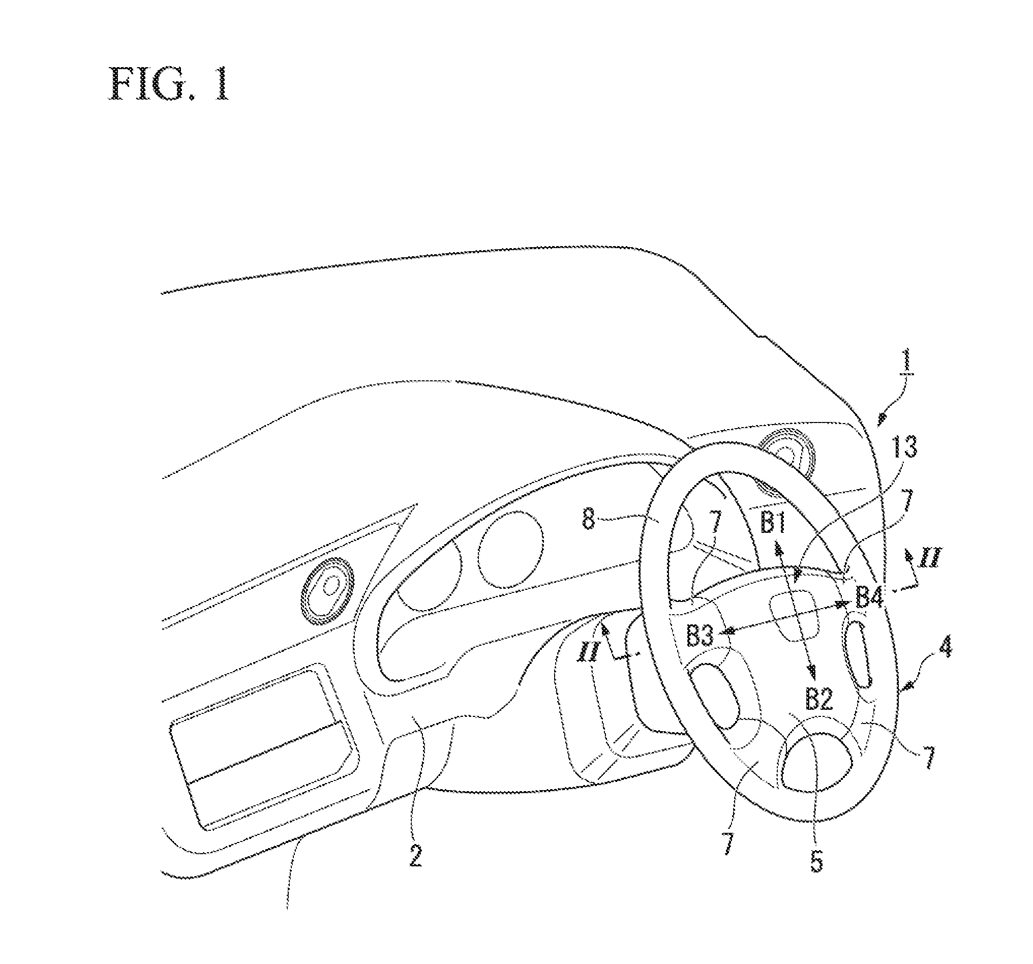
The present invention relates to a steering wheel structure in which an air-bag module is integrally attached to a horn operation unit. In most air-bag apparatuses provided on a driver's seat side, an air-bag module is integrally attached to the inside of a horn operation unit of a steering wheel. In this case, a horn block to which the horn operation unit and the air-bag module are integrally attached is attached by a support pin made of a metal to a steering wheel main body supported by a steering shaft. As this kind of steering wheel structure, a structure is known in which one end part of a support pin is locked to any one of a horn block and a steering wheel main body, a rubbery elastic component is interposed between the other of the horn block and the steering wheel main body and the other end part of the support pin, and according to the mass of the horn block and the elastic component, a dynamic damper for suppressing the vibration of the steering wheel is formed (for example, refer to Patent Document 1). In the steering wheel structure described in Patent Document 1, a connection unit that connects a horn block to a steering wheel main body includes a support pin having one end part that is locked to the horn block; a rubbery elastic component; and inner and outer members made of a resin held by the support pin in a state where the elastic component is sandwiched. The inner member is supported by the horn block via a coil spring, and the outer member is connected to the steering wheel main body. In the steering wheel structure, the elastic component sandwiched by the inner member and the outer member made of a resin functions as a spring of a dynamic damper, and the horn block is caused to resonate with vehicle vibration to thereby attenuate the vibration of the steering wheel. Further, in the steering wheel structure, the elastic component is not directly attached to a metal member on the steering wheel main body side but is locked to the steering wheel main body side via the outer member made of a resin, and therefore, it is possible to prevent the elastic member from coming into contact directly with the metal member and being worn early. [Patent Document 1] Japanese Patent No. 5523996 However, in the steering wheel structure of the related art described above, since the elastic component that functions as the spring of the dynamic damper is used in a state where the elastic component is merely sandwiched by the inner member and the outer member, an unpredictable transmission loss of vibration increases while the vibration is transmitted to the elastic component, and it is difficult to set the property such as an attenuation frequency of the dynamic damper with high accuracy. A problem to be solved is to set the property of the dynamic damper with high accuracy. An aspect of the present invention is a steering wheel structure including: a steering wheel main body supported by a steering shaft; a horn block to which a horn operation unit and an air-bag module are attached; and a connection unit that connects the horn block to the steering wheel main body such that the horn block can be elastically displaced with respect to the steering wheel main body, wherein the connection unit includes a support pin having one end supported by any one of the horn block and the steering wheel main body, a cylinder component having an outer circumferential part attached to the other of the horn block and the steering wheel main body, and an elastic component arranged between the cylinder component and the support pin, and wherein the elastic component is fixed to the cylinder component. Thereby, when vehicle vibration is input via the steering shaft to the steering wheel main body, the horn block resonates such that the elastic component fixed to the cylinder component is a spring. At this time, the elastic component and the cylinder component are fixed to each other, and therefore, the transmission efficiency of the vibration is enhanced. Further, the elastic component is not directly fixed to the other of the horn block and the steering wheel main body but is fixed, via the cylinder component fixed to the elastic component fixed, to the other of the horn block and the steering wheel main body. Therefore, early degradation of the elastic component is prevented. An aspect of the present invention is characterized in that the elastic component is fixed to the cylinder component and the support pin. In this case, the cylinder component and the elastic component are fixed to each other, and the elastic component and the support pin are fixed to each other. Therefore, the transmission efficiency of the vibration is further enhanced. An aspect of the present invention is characterized in that the support pin has a shaft part and a head part provided at one end of the shaft part and having a larger diameter than the shaft part, and the elastic component is fixed to the head part in a non-contact state with the shaft part of the support pin. In this case, a gap is formed between the circumferential area of the shaft part of the support pin and the elastic component, and the elastic component is easily vibrated further flexibly when the vehicle vibration is input. Accordingly, it is possible to further improve the attenuation performance of the dynamic damper. An aspect of the present invention is characterized in that the elastic component has a circumferential wall part that is fixed to an inside of the cylinder component and a beam part that is fixed to the support pin and extends radially outward to be connected to the circumferential wall part. In this case, around the circumferential wall part of the elastic component, the vibration property such as a resonation frequency is changed between a section where the beam part is present and a section where the beam part is absent. Therefore, by considering the position of the beam part when provided at the steering wheel, it is possible to obtain a property advantageous for attenuation corresponding to the input direction of vibration as an attenuation target. An aspect of the present invention is characterized in that the elastic component has an inner circumferential wall part that is connected to the beam part and is fixed to an outer circumferential surface of the shaft part of the support pin. In this case, the beam part of the elastic component is rigidly and stably fixed to the shaft part of the support pin via the inner circumferential wall part. An aspect of the present invention is characterized in that the elastic component is provided to extend at a region where at least the cylinder component and the shaft part of the support pin axially overlap with each other. In this case, even when a large load is input diagonally to the horn block when the horn is operated or the like, it is possible to prevent the cylinder component from coming into contact with the shaft part of the support pin and generating an abnormal sound. An aspect of the present invention is characterized in that the support pin is fixed to any one of the horn block and the steering wheel main body, the connection unit further includes a guide component having a cylinder shape and slidably held by the support pin, and the elastic component is fixed to the cylinder component and the guide component. In this case, when the horn is operated or the like, the support pin is not displaced in accordance with the displacement of the horn block, and the guide component slides on the support pin. An aspect of the present invention is characterized in that the elastic component has a circumferential wall part that is fixed to an inside of the cylinder component and a beam part that is fixed to the guide component and extends radially outward to be connected to the circumferential wall part. In this case, around the circumferential wall part of the elastic component, the vibration property such as a resonation frequency is changed between a section where the beam part is present and a section where the beam part is absent. Therefore, by considering the position of the beam part when provided at the steering wheel, it is possible to obtain a property advantageous for attenuation corresponding to the input direction of vibration as an attenuation target. An aspect of the present invention is characterized in that the elastic component has an inner circumferential wall part that is connected to the beam part and is fixed to an outer circumferential surface of a cylinder part of the guide component. In this case, the beam part of the elastic component is rigidly and stably fixed to the cylinder part of the guide component via the inner circumferential wall part. An aspect of the present invention is characterized in that the guide component has a cylinder part and a flange part that projects radially outward from one end in an axis direction of the cylinder part, and the elastic component is fixed to the flange part in a non-contact state with the cylinder part of the guide component. In this case, a gap is formed between the circumferential area of the cylinder part of the guide component and the elastic component, and the elastic component is easily vibrated further flexibly when the vehicle vibration is input. Accordingly, it is possible to further improve the attenuation performance of the dynamic damper. An aspect of the present invention is characterized in that the elastic component is provided to extend at a region where at least the cylinder component and the cylinder part of the guide component axially overlap with each other. In this case, even when a large load is input diagonally to the horn block when the horn is operated or the like, it is possible to prevent the cylinder component from coming into contact with the guide component and generating an abnormal sound. An aspect of the present invention is characterized in that the support pin is fixed to any one of the horn block and the steering wheel main body, the connection unit further includes a guide component having a cylinder shape and slidably held by the support pin, and one end part in an axis direction of the elastic component is fixed to the cylinder component and the other end part in the axis direction of the elastic component is fixed to the guide component or is pressed to be in contact with the guide component in use. In this case, when the horn is operated or the like, the support pin is not displaced in accordance with the displacement of the horn block, and the guide component slides on the support pin. Further, the one end part in the axis direction of the elastic component is integrated with the cylinder component, and the other end part in the axis direction of the elastic component is displaced integrally with the guide component at least in use. An aspect of the present invention is characterized in that a bias spring that is arranged between the guide component and any one of the horn block and the steering wheel main body and biases the horn block toward an initial position is provided, the support pin has a regulation part that regulates a displacement in the initial position direction of the guide component, and the guide component has a load reception flange part having a first surface which is directed in one of the axis direction and to which the elastic component is fixed or with which the elastic component is pressed to be in contact in use and a second surface which is directed in the other of the axis direction and which receives a bias load of the bias spring. In this case, the bias load of the bias spring directed to the initial position direction works on the guide component, and the displacement in the initial position direction of the guide component is regulated by the regulation part on the support pin. An aspect of the present invention is characterized in that the elastic component includes an extension part which is joined to the first surface of the load reception flange part and which is fixed to a region facing the regulation part or is pressed to be in contact with the region facing the regulation part in use. In this case, the regulation part on the support pin comes into contact with the load reception flange part of the guide component via the extension part of the elastic component. Thereby, an impact or a contact sound when the guide component is regulated by the regulation part is absorbed by the extension part of the elastic component. Accordingly, by adopting this configuration, it is possible to suppress a noise or vibration generated when the guide component is regulated by the regulation part. An aspect of the present invention is characterized in that a contact member that comes into contact directly with any one of the horn block and the steering wheel main body is attached to one end of the support pin, a support hole with which the contact member comes into contact and by which the contact member is supported is provided on any one of the horn block and the steering wheel main body, and a taper part that comes into contact with an inner surface of the support hole when the support pin is fixed to any one of the horn block and the steering wheel main body is provided on the contact member. In this case, when the one end of the support pin is fixed to any one of the horn block and the steering wheel main body, the taper part of the contact member attached to the one end of the support pin comes into contact with the inner surface of the support hole, and thereby, the support pin is positioned with respect to any one of the horn block and the steering wheel main body. Further, even when the support pin may receive an external force and be slightly fluctuated in the axis direction, the taper part comes into contact with the inner surface of the support hole, and thereby, the support pin is automatically returned to the appropriate position. According to an aspect of the present invention, since the elastic component that functions as the spring of the dynamic damper is fixed to the cylinder component, a transmission loss of vibration around the elastic component is decreased, and as a result, it is possible to set the property, such as an attenuation frequency of the dynamic damper, with high accuracy. Hereinafter, embodiments of the invention will be described based on the drawings. In the following description, the extension direction of a steering shaft 3 indicated by an arrow A direction in the drawing is defined as an “axis direction”. The directions orthogonal to the longitudinal direction of the steering shaft 3 indicated by arrows B, B1 to B4 directions in the drawing are defined as an “axis orthogonal direction”. In the embodiments, a mutual part is given by the same reference numeral, and a redundant description is omitted. First, a first embodiment shown in As shown in the figures, in the steering wheel 1, a steering wheel main body 4 that is gripped by a driver is attached to a front end part of the steering shaft 3 that protrudes rearward toward the inside of the vehicle interior from an instrument panel 2, and a steering pad 5 which is a horn operation unit is arranged at a center region of the steering wheel main body 4. The steering wheel main body 4 includes a cover unit 6 (refer to A recess space 11 that is recessed toward the vehicle body frontward direction is provided between the cover unit 6 at the center part of the steering wheel main body 4 and the rim unit 8 at the outer circumferential part, and a horn block 13 that integrates an air-bag module 12 and the steering pad 5 is arranged in the recess space 11. As shown in The rear surface (vehicle interior side surface) of the air-bag module 12 is covered by the steering pad 5 which is the horn operation unit. A connection wall 20 is provided to protrude frontward from an outer circumferential edge part of the steering pad 5 and is fastened to be fixed by a bolt 21 and a nut 22 to an outer circumferential edge part of the second retainer 17. In this way, the horn block 13 that is formed by integrating the air-bag module 12 and the steering pad 5 is locked in a floating state to the core metal 9 of the steering wheel main body 4 by three connection units 23. In the case of the embodiment, two of the connection units 23 are provided at right and left positions of an upper part of the steering shaft 3, and one of the connection units 23 is provided at a center position of a lower part of the steering shaft 3. All the connection units 23 have the same structure. In The connection unit 23 includes a support pin 24 having one end supported by the steering wheel main body 4, an outer collar 33 which is a cylinder component made of a resin and has an outer circumferential part attached to the horn block 13, and an elastic component 29 formed of a rubber, an elastic resin, or the like interposed between the outer collar 33 and the support pin 24. The elastic component 29 is, for example, formed of a rubber such as an EPDM. The elastic component 29 forms a spring of a dynamic damper in which the horn block 13 is a damper mass. The support pin 24 is, for example, formed of a metal such as a stainless steel. A spring retainer 30 is attached integrally to the support pin 24 at a substantially center position in the axis direction. A horn spring 25 that biases the horn block 13 in the initial position direction (direction away from the cover unit 6) is interposed between the spring retainer 30 and the cover unit 6 of the steering wheel main body 4. One end part (vehicle body front side) of the support pin 24 is retained in a state where a slight axis direction displacement is allowed by the cover unit 6 of the steering wheel main body 4, and the other end part (part positioned on the vehicle body rear side) is locked to be fixed to the second retainer 17 of the horn block 13 via the elastic component 29 and the outer collar 33. A taper part 32 having a decreased diameter toward the extension end is formed at one end part in the axis direction of the support pin 24, and a head part 24 A pair of horn contact points 26A, 26B that forms a horn switch is attached at positions facing each other in the axis direction of the second retainer 17 of the horn block 13 and the cover unit 6 of the steering wheel main body 4. The horn contact points 26A. 26B are in a separated state (non-contact state) when the horn block 13 is biased by the horn sprint 25 to be positioned in the vicinity of the initial position. When the horn block 13 is operated to be pressed by a set stroke or more from the state, the horn contact points 26A, 26B come into contact with each other to operate the horn. A cutout groove 34 recessed in an axis perpendicular direction is formed at a part of the outer circumferential surface close to one end part of the support pin 24, the part being adjacent to the enlarged diameter side of the taper part 32. As shown in A guide bush 47 is pressed into the support hole 35 of the cover unit 6 from a part (vehicle body rear side) facing the recess space 11. One end part of the support pin 24 is slidably guided by the guide bush 47. In the guide bush 47, a flange part 47 The elastic component 29 is formed such that the entire shape is a cylinder shape. A large diameter cylinder part 29 In the outer collar 33 made of a resin, a large diameter cylinder part 33 The elastic component 29 interposed between the support pin 24 and the outer collar 33 is fixed to the support pin 24 and the outer collar 33 at the time of manufacturing. In the case of this embodiment, the elastic component 29 is fixed to the support pin 24 and the outer collar 33 according to vulcanization adhesion. The elastic component 29 may be fixed to the support pin 24 and the outer collar 33 according to a means other than vulcanization adhesion which is, for example, an adhesive agent and the like. The end surface of the large diameter cylinder part 29 In the elastic component 29, the general cylinder part 29 The elastic component 29 fixed to the support pin 24 and the outer collar 33 as described above is provided to extend at a region where at least the outer collar 33 and the shaft part 24 In the case of this embodiment, the connection unit 23 is attached in advance to the second retainer 17 of the horn block 13 in a state where the spring retainer 30 and the horn spring 25 are attached to the support pin 24. In this way, the front end part of the support pin 24 attached to the horn block 13 is inserted into the corresponding guide bush 47 and the support hole 35 on the cover 6 side. At this time, when the front end parts of the support pins 24 are inserted into the guide bush 47 and the support hole 35, one end of the horn spring 25 having the other end held by the support pin 24 comes into contact with the corresponding flange part 47 In this way, when the support pin 24 is inserted into the guide bush 47 and the support hole 35, the taper part 32 on the front end side of the support pin 24 pushes and moves the locking member 36, and at the timing when the support pin 24 is inserted by a predetermined amount, the locking member 36 elastically returns and is inserted into the cutout groove 34 of the support pin 24. As a result, the horn block 13 is locked to be fixed to the steering wheel main body 4 via the connection unit 23. In this embodiment, the horn block 13 and the elastic components 29 of the connection units 23 form the dynamic damper that attenuates vibration of the steering wheel 1. The vibration system formed of the horn block 13 and the elastic component 29 is tuned so as to resonate with vibration in a frequency range such as engine vibration or travel vibration input to the steering wheel 1. Next, the operation of each unit when the horn block 13 is operated as a horn and when the horn block 13 functions as a dynamic damper is described. When the steering pad 5 is pushed by the driver for the horn operation during driving of the vehicle or the like, a load in the press direction is input to the support pin 24 of the connection unit 23. In this way, when the operation load is input to the support pin 24, the horn spring 25 is compressively deformed, and the entire horn block 13 is pressed. At the timing when the horn block 13 is displaced by a set stroke or more, the horn contact points 26A, 26B come into contact with each other, and as a result, the horn is operated. On the other hand, during the horn block 13 is not operated to be pressed, the outer collar 33 of the connection unit 23 fixed to the horn block 13 is supported in a displaceable manner by the end part of the support pin 24 via the elastic component 29. From this state, when engine vibration, travel vibration, or the like is input to the steering wheel 1, the vibration system in which the horn block 13 is a damper mass and the elastic component 29 is a spring resonates, and as a result, the vibration of the steering wheel 1 is attenuated. As described above, in the steering wheel structure according to this embodiment, the rubbery elastic component 29 of the connection unit 23 is fixed to each of the outer collar 33 made of a resin and the support pin 24 made of a metal according to vulcanization adhesion or the like, and therefore, the vibration transmission loss inside the connection unit 23 is extremely low. Therefore, when the steering wheel structure according to this embodiment is employed, it is possible to set the property such as the attenuation frequency of the dynamic damper with high accuracy. Further, in the steering wheel structure, the elastic component 29 of the connection unit 23 is not directly fixed to the second retainer 17 made of a metal of the horn block 13 but is fixed to the outer collar 33 made of a resin, and the outer collar 33 is locked to be fixed to the second retainer 17. Therefore, it is possible to prevent the elastic component 29 from coming into contact directly with the metal member and prevent the contacting end part from being degraded. Further, in the steering wheel structure according to this embodiment, since the elastic component 29 of the connection unit 23 is fixed only to the head part 24 Further, in the case of the steering wheel structure according to this embodiment, the elastic component 29 is provided to extend at a region where the outer collar 33 and the shaft part 24 Next, a second embodiment shown in In the second embodiment, only the structure of a connection unit 123 is different from that of the first embodiment. The connection unit 123 according to the second embodiment includes a support pin 24 having one end part supported by the steering wheel main body, an outer collar 33 made of a resin and having an outer circumferential part attached to the horn block, and an elastic component 129 formed of a rubber, an elastic resin, or the like interposed between the outer collar 33 and the support pin 24 and fixed to the outer collar 33 and the support pin 24 according to vulcanization adhesion or the like. The shape of the elastic component 129 and the fixation part of the elastic component 129 and the support pin 24 of the connection unit 123 of this embodiment are different from those of the first embodiment. The elastic component 129 has a circumferential wall part 129 The entire region of the end surface of each beam part 129 The four beam parts 129 In the elastic component 129 of this embodiment, the outer collar 33 and the support pin 24 are connected mainly via the four beam parts 129 The elastic component 129 is provided to extend at least at a region where the outer collar 33 and the shaft part 24 Even in the case of this embodiment, since the elastic component 129 of the connection unit 123 is fixed to each of the outer collar 33 and the support pin 24 according to vulcanization adhesion or the like, the vibration transmission loss inside the connection unit 123 is extremely low, and it is possible to obtain an advantage substantially similar to the first embodiment. Further, in the steering structure according to this embodiment, the elastic component 129 that forms the connection unit 123 has the circumferential wall part 129 In a case where the property of the elastic component is changed in consideration of the input direction of vibration, for example, the rotation position around the shaft center at the time of installation of the elastic component 129 may be changed, or the extension direction of the beam part 129 Further, in the steering structure according to this embodiment, the inner end parts in the radial direction of the plurality of the beam parts 129 Further, in the embodiment described above, the beam parts 129 Next, a third embodiment shown in In the third embodiment, only the structure of the connection unit 223 is different from those of the first embodiment and the second embodiment. The connection unit 223 according to the third embodiment includes a support pin 224 having one end part supported by the steering wheel main body 4, the outer collar 33 made of a resin and having an outer circumferential part attached to the horn block 13, and the elastic component 129 formed of a rubber, an elastic resin, or the like interposed between the outer collar 33 and the support pin 224. The connection unit 223 according to the third embodiment is different from those of the first embodiment and the second embodiment. One end part of the support pin 224 is fixed to the steering wheel main body 4 in a substantially non-displaceable manner, and the elastic component 129 is fixed not to the support pin 224 but to a guide component 39 in a separate body according to vulcanization adhesion or the like. The guide component 39 is formed of a resin in a cylinder shape and is slidably held by a shaft part 224 In the connection unit 223 according to this embodiment, at the time of the horn operation of the horn block 13 or the like, the support pin 224 is not displaced, but the guide component 39 on the inner side is slid to be displaced on the shaft part 224 As shown in The elastic component 129 has a circumferential wall part 129 The entire region of the end surface of each beam part 129 The four beam parts 129 A taper part 232 having a decreased diameter toward the extension end to form a conical shape is formed at one end part in the axis direction of the support pin 224. A locking groove 40 having an annular shape is formed at a position adjacent to the taper part 232 of the shaft part of the support pin 224. As shown in A spring retainer 330 which is made of a resin and supports one end part of the horn spring 25 is fitted to the outer circumference on the front end side of the cylinder part 39 In the case of this embodiment, when the steering pad is pushed by the driver for the horn operation during driving of the vehicle or the like, a load in the press direction is input to the spring retainer 330 via the elastic component 129 and the guide component 39 from the outer collar 33 of the connection unit 223. In this way, when the operation load is input to the spring retainer 330, as shown in When the horn block 13 is not operated, and when engine vibration, travel vibration, or the like is input to the steering wheel, the vibration system in which the horn block 13 is a damper mass and the elastic component 129 is a spring resonates, and the vibration of the steering wheel is attenuated. In the steering wheel structure according to this embodiment, the elastic component 129 of the connection unit 223 is fixed to each of the outer collar 33 and the guide component 39 according to vulcanization adhesion or the like, and therefore, it is possible to reduce the vibration transmission loss inside the connection unit 223. Therefore, even in the case of this embodiment, it is possible to set the property such as the attenuation frequency of the dynamic damper with high accuracy. Further, in the steering structure according to this embodiment, the elastic component 129 of the connection unit 223 includes the circumferential wall part 129 Further, in the steering structure according to this embodiment, the inner end parts in the radial direction of the plurality of the beam parts 129 The shape of the elastic component 29 and the fixation part of the elastic component 29 and the support pin 224 of the connection unit 323 according to the fourth embodiment are different from those of the third embodiment, and the rest of configurations are the same as those of the third embodiment. Similarly to that of the first embodiment, the elastic component 29 is formed such that the entire shape is a cylinder shape, a large diameter cylinder part 29 Even in the case of the fourth embodiment, it is possible to obtain a basic action and advantage similar to the third embodiment described above. Further, in the fourth embodiment, since the elastic component 29 of the connection unit 323 is fixed only to the flange part 39 Next, a fifth embodiment shown in In the fifth embodiment, the structure of the connection unit 423 is different from that of the first to fourth embodiments. The connection unit 423 according to the fifth embodiment includes a support pin 424 having one end part fixed to the steering wheel main body 4 in a substantially non-displaceable manner, an outer collar 433 (cylinder component) made of a resin and having an outer circumferential part attached to the horn block 13, and a guide component 439 slidably held by the support pin 424, and an elastic component 429 interposed between the outer collar 433 and the guide component 439 and fixed to each of the outer collar 433 and the guide component 439 according to vulcanization adhesion or the like. The elastic component 429 forms a spring of a dynamic damper in which the horn block 13 is a damper mass. The support pin 424 is formed of a first pin member 424A arranged on the horn block 13 side and a second pin member 424B arranged on the steering wheel main body 4 side, and the first pin member 424A and the second pin member 424B are concentrically connected to each other. The first pin member 424A and the second pin member 424B are formed of a metal such as a stainless steel or a hard resin. The first pin member 424A is formed such that the entire shape is a substantially cylinder shape. The first pin member 424A includes a large diameter shaft part 424A-a, a small diameter shaft part 424A-b having a smaller outer diameter than the large diameter shaft part 424A-a, a regulation part 424A-c formed of a step surface having a taper shape between the large diameter shaft part 424A-a and the small diameter shaft part 424A-b, and a head part 424A-d formed, so as to project outward in the radial direction, at the end part on the opposite side of the regulation part 424A-c of the large diameter shaft part 424A-a. The second pin member 424B includes a press fit shaft part 424B-a that is pressed into the inner circumference of the small diameter shaft part 424A-b of the first pin member 424A and a base part-side shaft part 424B-b that protrudes axially outward from the small diameter shaft part 424A-b when the press fit shaft part 424B-a is pressed into the small diameter shaft part 424A-b. The base part-side shaft part 424B-b has a stopper flange 41 having a decreased diameter in a two-step manner toward the small diameter shaft part 424A-b and a taper part 432 having a conical shape and continuously provided to interpose the locking groove 40 having an annular shape on the outer side in the axis direction of the stopper flange 41. As shown in The outer collar 433 is formed such that the entire shape is a substantially cylinder shape. The outer collar 433 has an outer circumferential part attached to an attachment hole 13 The guide component 439 has a cylinder part 439 A recess part 42 having a taper shape is formed on the inner circumferential edge part of the front surface (first surface) of the load reception flange part 439 The elastic component 429 is formed such that the entire shape is a substantially cylinder shape. A large diameter cylinder part 429- In the elastic component 429, the outer circumferential surface of the general cylinder part 429- A gap is provided between the inner circumferential surface of the elastic component 429 and the large diameter shaft part 424A-a of the first pin member 424A at the entire region of the inner circumferential surface of the elastic component 429 excluding the extension part 429- A contact member 43 made of a resin and in contact with a surface (surface on the vehicle interior side) on the rear side of the steering wheel main body 4 is attached to a part between the extension end part of the small diameter shaft part 424A-b of the first pin member 424A and the stopper flange 41 of the second pin member 424B. The contact member 43 has a head part 43 A recess surface 435 In the connection unit 423, in a state where the outer collar 433, the elastic component 429, and the guide component 439 that are mutually fixed are externally provided on the large diameter shaft part 424A-a of the first pin member 424A, and the horn spring 425 is interposed between the load reception flange part 439 The extension end of the support pin 424 attached to the horn block 13 and the taper part 43 In this way, when the support pin 424 is inserted into the support hole 435, the taper part 432 of the support pin 424 pushes and moves the locking member 36, and at the timing when the support pin 424 is inserted by a predetermined amount, the locking member 36 elastically returns and is engaged with the inside of the locking groove 40 of the support pin 424. As a result, the horn block 13 is locked to be fixed to the steering wheel main body 4 via the connection unit 423. In this embodiment, when the steering pad is pushed by the driver for the horn operation during driving of the vehicle or the like, an operation load is input to the horn spring 425 via the elastic component 429 and the guide component 439 from the outer collar 433 of the connection unit 423. In this way, when the operation load is input to the horn spring 425, as shown in From this state, when the press operation of the steering pad is released, the entire horn block 13 is displaced in the initial position direction according to the elasticity of the horn spring 425. At this time, when the guide component 439 of the connection unit 423 is displaced in the initial position direction by a predetermined amount, the recess part 42 of the guide component 439 comes into contact with the regulation part 424A-c of the support pin 424 via the extension part 429- On the other hand, in a state where the horn block 13 is not operated, when engine vibration, travel vibration, or the like is input to the steering wheel, the vibration system in which the horn block 13 is a damper mass and the elastic component 429 is a spring resonates, and the vibration of the steering wheel is attenuated. In the case of the steering wheel structure according to the fifth embodiment, the elastic component 429 of the connection unit 423 is fixed to each of the outer collar 433 and the guide component 439 according to vulcanization adhesion or the like, and therefore, the vibration transmission loss inside the connection unit 423 is reduced. Therefore, similarly to the first to fourth embodiments, it is possible to set the property such as the attenuation frequency of the dynamic damper with high accuracy. Further, in the steering wheel structure according to this embodiment, the load reception flange part 439 Specifically, in this embodiment, the regulation part 424A-c on the support pin 424 side is formed of a step surface having a taper shape, and the extension part 429- Further, in the steering wheel structure according to this embodiment, the contact member 43 is attached to the support pin 424, and the taper part 43 The invention is not limited to the embodiments described above, and a variety of design modifications can be made to the embodiments without departing from the scope of the invention. For example, in the first embodiment, a plurality of beam parts are not provided on the elastic component 29; however, a plurality of beam parts may be provided in place of the large diameter cylinder part 29 Further, in the first and second embodiments, one end part of the support pin is locked to the steering wheel main body side, and the other end part of the support pin is attached to the horn block side via the elastic component and the cylinder component made of a resin; however, conversely, one end part of the support pin may be locked to the horn block side, and the other end part of the support pin may be attached to the steering wheel main body side via the elastic component and the cylinder component made of a resin. Similarly, in the third to fifth embodiments, one end part of the support pin is locked to the steering wheel main body side, and the guide component slidably held by the support pin is connected to the horn block side via the elastic component and the outer collar which is a cylinder member; however, conversely, one end part of the support pin may be locked to the horn block side, and the guide component slidably held by the support pin may be connected to the steering wheel main body side via the elastic component and the outer collar. Further, in the embodiments described above, the elastic component is fixed not only to the outer collar which is a cylinder component but also to the support pin or the guide component; however, the elastic member may be fixed only to the cylinder component. Specifically, in the fifth embodiment, the elastic member and the guide component may be pressed to be in contact with each other in use. A steering wheel structure includes: a steering wheel main body supported by a steering shaft; a horn block to which a horn operation unit and an air-bag module are attached; and a connection unit that connects the horn block to the steering wheel main body such that the horn block can be elastically displaced with respect to the steering wheel main body, wherein the connection unit includes a support pin having one end supported by any one of the horn block and the steering wheel main body, a cylinder component having an outer circumferential part attached to the other of the horn block and the steering wheel main body, and an elastic component arranged between the cylinder component and the support pin, and wherein the elastic component is fixed to the cylinder component. 1-15. (canceled) 16. A steering wheel structure, comprising:
a steering wheel main body supported by a steering shaft; a horn block to which a horn operation unit and an air-bag module are attached; and a connection unit that connects the horn block to the steering wheel main body such that the horn block can be elastically displaced with respect to the steering wheel main body, wherein the connection unit comprises
a support pin having one end supported by any one of the horn block and the steering wheel main body, a cylinder component having an outer circumferential part attached to the other of the horn block and the steering wheel main body, and an elastic component arranged between the cylinder component and the support pin, the elastic component is fixed to the cylinder component and the support pin, the support pin has a shaft part and a head part provided at one end of the shaft part and having a larger diameter than the shaft part, and the elastic component is fixed to the head part in a non-contact state with the shaft part of the support pin. 17. A steering wheel structure, comprising:
a steering wheel main body supported by a steering shaft; a horn block to which a horn operation unit and an air-bag module are attached; and a connection unit that connects the horn block to the steering wheel main body such that the horn block can be elastically displaced with respect to the steering wheel main body, wherein the connection unit comprises
a support pin having one end supported by any one of the horn block and the steering wheel main body, a cylinder component having an outer circumferential part attached to the other of the horn block and the steering wheel main body, and an elastic component arranged between the cylinder component and the support pin, the elastic component is fixed to the cylinder component and the support pin, and the elastic component has a circumferential wall part that is fixed to an inside of the cylinder component and a beam part that is fixed to the support pin and extends radially outward to be connected to the circumferential wall part. 18. The steering wheel structure according to the elastic component has an inner circumferential wall part that is connected to the beam part and is fixed to an outer circumferential surface of the shaft part of the support pin. 19. The steering wheel structure according to the elastic component is provided to extend at a region where at least the cylinder component and the shaft part of the support pin axially overlap with each other. 20. The steering wheel structure according to the elastic component is provided to extend at a region where at least the cylinder component and the shaft part of the support pin axially overlap with each other. 21. The steering wheel structure according to the elastic component is provided to extend at a region where at least the cylinder component and the shaft part of the support pin axially overlap with each other. 22. A steering wheel structure, comprising:
a steering wheel main body supported by a steering shaft; a horn block to which a horn operation unit and an air-bag module are attached; and a connection unit that connects the horn block to the steering wheel main body such that the horn block can be elastically displaced with respect to the steering wheel main body, wherein the connection unit comprises
a support pin having one end supported by any one of the horn block and the steering wheel main body, a cylinder component having an outer circumferential part attached to the other of the horn block and the steering wheel main body, and an elastic component arranged between the cylinder component and the support pin, the support pin is fixed to any one of the horn block and the steering wheel main body, the connection unit further comprises a guide component having a cylinder shape and slidably held by the support pin, the elastic component is fixed to the cylinder component and the guide component, and the elastic component has a circumferential wall part that is fixed to an inside of the cylinder component and a beam part that is fixed to the guide component and extends radially outward to be connected to the circumferential wall part. 23. The steering wheel structure according to the elastic component has an inner circumferential wall part that is connected to the beam part and is fixed to an outer circumferential surface of a cylinder part of the guide component. 24. A steering wheel structure, comprising:
a steering wheel main body supported by a steering shaft; a horn block to which a horn operation unit and an air-bag module are attached; and a connection unit that connects the horn block to the steering wheel main body such that the horn block can be elastically displaced with respect to the steering wheel main body, wherein the connection unit comprises
a support pin having one end supported by any one of the horn block and the steering wheel main body, a cylinder component having an outer circumferential part attached to the other of the horn block and the steering wheel main body, and an elastic component arranged between the cylinder component and the support pin, the support pin is fixed to any one of the horn block and the steering wheel main body, the connection unit further comprises a guide component having a cylinder shape and slidably held by the support pin, the elastic component is fixed to the cylinder component and the guide component, the guide component has a cylinder part and a flange part that projects radially outward from one end in an axis direction of the cylinder part, and the elastic component is fixed to the flange part in a non-contact state with the cylinder part of the guide component. 25. The steering wheel structure according to the elastic component is provided to extend at a region where at least the cylinder component and the cylinder part of the guide component axially overlap with each other. 26. The steering wheel structure according to the elastic component is provided to extend at a region where at least the cylinder component and the cylinder part of the guide component axially overlap with each other. 27. The steering wheel structure according to the elastic component is provided to extend at a region where at least the cylinder component and the cylinder part of the guide component axially overlap with each other. 28. A steering wheel structure, comprising:
a steering wheel main body supported by a steering shaft; a horn block to which a horn operation unit and an air-bag module are attached; and a connection unit that connects the horn block to the steering wheel main body such that the horn block can be elastically displaced with respect to the steering wheel main body, wherein the connection unit comprises
a support pin having one end supported by any one of the horn block and the steering wheel main body, a cylinder component having an outer circumferential part attached to the other of the horn block and the steering wheel main body, and an elastic component arranged between the cylinder component and the support pin, the support pin is fixed to any one of the horn block and the steering wheel main body, the connection unit further comprises a guide component having a cylinder shape and slidably held by the support pin, and one end part in an axis direction of the elastic component is fixed to the cylinder component and the other end part in the axis direction of the elastic component is attached to the guide component in a fixation state or a press contact state. 29. The steering wheel structure according to a bias spring that is arranged between the guide component and any one of the horn block and the steering wheel main body and biases the horn block toward an initial position is provided, the support pin has a regulation part that regulates a displacement in the initial position direction of the guide component, and the guide component has a load reception flange part having a first surface which is directed in one of the axis direction and to which the elastic component is attached in a fixation state or a press contact state and a second surface which is directed in the other of the axis direction and which receives a bias load of the bias spring. 30. The steering wheel structure according to the elastic component comprises an extension part which is joined to the first surface of the load reception flange part and which is attached to a region facing the regulation part in a fixation state or a press contact state. 31. The steering wheel structure according to a contact member that comes into contact directly with any one of the horn block and the steering wheel main body is attached to one end of the support pin, a support hole with which the contact member comes into contact and by which the contact member is supported is provided on any one of the horn block and the steering wheel main body, and a taper part that comes into contact with an inner surface of the support hole when the support pin is fixed to any one of the horn block and the steering wheel main body is provided on the contact member. 32. The steering wheel structure according to a contact member that comes into contact directly with any one of the horn block and the steering wheel main body is attached to one end of the support pin, a support hole with which the contact member comes into contact and by which the contact member is supported is provided on any one of the horn block and the steering wheel main body, and a taper part that comes into contact with an inner surface of the support hole when the support pin is fixed to any one of the horn block and the steering wheel main body is provided on the contact member. 33. The steering wheel structure according to a contact member that comes into contact directly with any one of the horn block and the steering wheel main body is attached to one end of the support pin, a support hole with which the contact member comes into contact and by which the contact member is supported is provided on any one of the horn block and the steering wheel main body, and a taper part that comes into contact with an inner surface of the support hole when the support pin is fixed to any one of the horn block and the steering wheel main body is provided on the contact member.TECHNICAL FIELD
BACKGROUND
RELATED ART DOCUMENTS
Patent Documents
SUMMARY OF INVENTION
Problems to be Solved by the Invention
Means for Solving the Problem
Advantage of the Invention
BRIEF DESCRIPTION OF THE DRAWINGS
DESCRIPTION OF THE EMBODIMENTS
DESCRIPTION OF THE REFERENCE SYMBOLS