PUSH SWITCH
Field of the Invention The present invention relates to a push switch. Description of Relevant Art In a known push switch, pushing down an operation body makes a ring-shaped movable contact rotate relative to a fixed contact, thereby switching contacts (Patent document (1): Patent application publication laid-open No. 2009-59578)). The push switch includes a cam follower to rotate stepwise by a push operation; a resinous operation member to rotate integrally with the cam follower; and an electrically energizable metallic movable contact to rotate integrally with the operation member. The movable contact is fixedly hung down from the operation member. Meanwhile, this push switch has a continuous problem that the number of components is reduced. The present invention is directed to a push switch including a smaller number of components. An aspect of the invention provides the following push switch. The push switch includes: a hollow housing having an inner circumferential surface formed with a guide part including a rotation restriction part and a return restriction part; an operation button including a first ratchet tooth extending in a circumferential direction and being movable up and down in an axial direction; a cam follower including a cam part configured to be guided to the rotation restriction part and the return restriction part; and a second ratchet tooth engaged with the first ratchet tooth, the cam follower being movable up and down in the axial direction and rotatable in the circumferential direction; a first spring urging the cam follower to come close to the operation button in a return direction so as to mesh the first ratchet tooth and the second ratchet tooth with each other; a metallic contact member including an engagement part engaged with the cam follower, and a movable contact and being configured to rotate integrally with the cam follower; a fixed contact configured to contact with the movable contact and including contacts to be switched by rotating the contact member; and a base on which the fixed contact is fixed. When the operation button is pushed in a return allowance state under which the cam part is disposed at the rotation restriction part, the cam part moves from the rotation restriction part to the return restriction part. The cam follower and the cam contact member rotates before the cam part locks with the return restriction part to come into a return restriction state under which the cam follower is restricted from returning. When the operation button is pushed in the return restriction state, the cam part moves from the return restriction part to the rotation restriction part. The cam follower and the contact member rotate before the cam part comes into the return allowance state. The contact member has a rotation center and defines a through hole at the rotation center. The base includes a rotation axis part inserted in the through hole and serving as the rotation center of the contact member. According to the aspect, the contact member functions as an operation member and a movable contact of the Patent Document (1), and the number of components of the push switch is reduced. The contact member preferably rotates about the rotation axis part of the base inserted through the through-hole of the contact member. The rotation axis part may include an end inserted in the first spring constructed of a coil spring. According to this element, the end of the rotation axis part is inserted in the first spring, thereby preventing the first spring from inclining. The base includes an annular pedestal part projecting over the fixed contact toward the contact member. According to this element, the annular pedestal part of the base prevents unnecessary short-circuit between the contact member and the fixed contact. According to the aspect of the present invention, the push switch with a smaller number of components is provided. The following description will be given of an embodiment of the present invention with reference to the <<Construction of Push Switch>> The push switch 1 is used as, for example, a switch to turn on or off a room lump for a vehicle.
<Operation Button> The operation button 10 is a component which an operator (driver etc.) directly operates, and is movable to the housing 50 in the axial direction (vertical direction). The operation button 10 is made of, for example, a thermoplastic rein. As illustrated in The cylindrical part 12 has a lower end surface formed with a first ratchet tooth 15 extending in the circumferential direction. The first ratchet tooth 15 includes eight ridges 15 The four guided parts 13 are arranged at equal angular intervals (90 degrees interval) (see The lower end of the axis part 14 extends through the through-hole 21 <Cam Follower> The cam follower 20 is a resinous double cylindrical member disposed in the housing 50 (see The bottom wall part 21 is formed at the center with a through hole 21 The inner cylinder part 22 and the axis part 14 have a cylindrical space formed therebetween, in which a second spring 80 is housed. The outer cylinder part 24 and the inner cylinder part 22 have a cylindrical space formed therebetween, in which a first spring 70 is housed. The flange part 25 is formed with a second ratchet tooth 27 on the top surface (see The flange part 25 is formed with two engagement holes 25 Note the engagement pieces 33 and the engagement holes 25 The four cam parts 26 are arranged at equal angular intervals (90 degrees interval) in the circumferential direction (see <Contact Member> The contact member 30 rotates relative to the fixed terminal 40 to switch contacts (see The contact member 30 includes a base part 31, a pair of tongue pieces 32, and a pair of engagement pieces 33 (engagement parts). The base part 31 is a plate-frame portion of a base, and formed with a through hole 31 The two tongue pieces 32 are arranged opposite to each other with the base part 31 and the axis O1 intervening between the tongue pieces 32. Each tongue piece 32 in an approximate semicircle extends radially outward from the base part 31 and obliquely downward relative to the base part 31 at an obtuse angle. The obtuse angle of each tongue piece 32 and the base part 31 is designed such that the movable contacts 32 The two movable contacts 32 The two engagement pieces 33 are elongated plate pieces extending upward from base part 31. The engagement pieces 33 are arranged at the intermediate between the neighboring tongue pieces 32 in the circumferential direction and opposite to each other with the axis O1 intervening between the engagement pieces 33. Namely, the two tongue pieces 32 and the two engagement pieces 33 are alternately arranged at equal angular intervals (90 degrees interval) in the circumferential direction. The two engagement pieces 33 are inserted in the two engagement holes 25 <Fixed Terminal> The fixed terminal 40 is, at a fixation side (non-rotation side), a terminal partially embedded in the base 60 (see The first fixed terminal 41 includes a first A fixed contact 41A exposed upward from the base 60. The first A contact 41A is formed in a semicircle about the axis O1 with a central angle of approximately 170 degrees. Thereby, even if the contact member 30 is disposed at any angular positions in the circumferential direction, one of the two movable contacts 32 The second fixed terminal 42 includes a second A fixed contact 42A and a second B fixed contact 42B each exposed upward from the base 60. The second A fixed terminal 42A and the second B fixed terminal 42B each represent a sector about the axis O1 with an central angle of approximately 40 degrees. The third fixed terminal 43 includes a third A fixed terminal 43A and a third B fixed terminal 43B each exposed upward from the base 60. The third A fixed contact 43A and the third B fixed contact 43B each represent a sector about the axis O1 with an central angle of approximately 40 degrees. In a planar view, the first A fixed contact 41A, the second A contact 42A, the third A fixed contact 43A, the second B fixed contact 42B, and the third B fixed contact 43B are arranged in order in the circumferential direction about the axis O1. Accordingly, when the contact member 30 rotates about the axis O1 by every 45 degrees, the two movable contacts 32 At the first position, the movable contacts 32 At the second position, the movable contacts 32 At the third position, the movable contacts 32 At the fourth position, the movable contacts 32 <Housing> The housing 50 is a cylindrical case of a hollow structure, and includes a columnar hollow part 51 inside thereof (see <Housing—Guide Part> The guide part 53 includes four rotation restriction parts 54 and four return restriction parts 55, and four introduction parts 56 (see The rotation restriction parts 54 are each constructed with a vertical groove which extends in the vertical direction (up-down direction), whose lower end is open, and whose upper is closed. In the rotation restriction parts 54, the guided parts 13 of the operation button 10 are housed slidably in the axial direction. Thereby, the operation button 10 is guided by the rotation restriction parts 54 in the axial direction, while being restricted from rotating about the axis O1 by the rotation restriction parts 54. When the cam part 26 of the cam follower 20 is housed in the rotation restriction part 54, the cam follower 20 is guided by the rotation restriction parts 54 in the axial direction, while being restricted from rotating about the axis O1 by the rotation restriction part 54. Namely, when the cam part 26 is housed in the rotation restriction part 54, the cam follower 20 comes into a “return allowed state” under which the cam follower 20 is allowed to return upward (see The return restriction part 55 and the introduction part 56 are recessed parts (cut-off parts) formed by recessing partially the lower portion of the inner circumference of the cylindrical housing 50 in the radially outer ward direction. The return restriction part 55 is a part to restrict the cam part 26 from moving upward and rotating. The return restriction part 55 includes a top wall surface 55 When the cam part 26 is disposed at the corner part 55 The introduction part 56 guides and introduces, to the rotation restriction part 54, the cam part 26 which is released downward from the return restriction part 55 by the push operation. The introduction part 56 includes an introduction surface 56 <Base> The base 60 is a resinous member forming a support of the push switch 1. The base 60 includes a base body 61, a rotation axis part 62, and a pedestal part 63 (see The rotation axis part 62 is a cylindrical part extending upward from the center of the bottom wall portion of the base body 61 along the axis O1. The rotation axis part 62 extends through the through-hole 31 The upper end portion of the rotation axis part 62 is also inserted in the lower portion of the first spring 70 (see The pedestal part 63 projects upward (contact member 30 side) of the first A fixed contact 41A, the second A contact 42A, the second B fixed contact 42B, the third A fixed contact 43A, and the third B fixed contact 43B. The pedestal part 63 slidably contacts with the base part 31, and prevents unnecessary short-circuit of the contact member 30 and the first A fixed contact 41A and the like. Thereby, the contact member 30, urged downward by the first spring 70, does not contact with the fixed contact 40 except for the two movable contacts 32 <First Spring> The first spring 70 is constructed of a compressed coil spring, and shrunkly disposed between the top wall part 23 of the cam follower 20 and the base part 31 of the contact member 30 (see <Second Spring> The second spring 80 is constructed of a compressed coil spring, and shrunkly disposed between the operation part 11 of the operation button 10 and the bottom wall part 21 of the cam follower 20 (see <Cover> The cover 90 has a reversed U-shape in a vertical section view. The cover 90 covers the housing 50, and the lower end portion of the cover 90 locks with the base 60. Thereby, the housing 50 and the base 60 are kept assembled together. <Operation and benefit of Push Switch> The operation of the push switch 1 is described with reference to When the cam part 26 is pushed down below the rotation restriction part 54 (see When the push operation is released, the first ratchet tooth 15 of the operation button 10 moves up. Meanwhile, the cam part 26 slides along the top wall surface 55 In the return restriction state, the push operation makes the first ratchet tooth 15 push down the cam part 26 (see When the push operation is released, the first ratchet tooth 15 of the operation button 10 moves up. Meanwhile, the cam part 26 slides along the introduction surface 56 Herein, the rotation restriction parts 54 are at angular intervals of 90 degrees in the circumferential direction, and the corner parts 55 The contact member 30 functions as two components of the operation member and the movable contact in the Patent Document (1), and the number of components is reduced. The contact member 30 is rotatable about the rotation axis part 62 without inclining. In addition, the upper portion of the rotation axis part 62 is inserted in the first spring 70, and the first spring is prevented from falling down. Though one embodiment of the invention is described above, the invention is not limited to the embodiment and may be appropriately modified. Modifications and variations of the embodiments described above will occur to those skilled in the art, in light of the above teachings. The scope of the invention is defined with reference to the following claims.
A push switch includes: a hollow housing having an inner circumferential surface formed with a guide part; an operation button formed with a first ratchet tooth; a cam follower including a cam part, and a second ratchet tooth, and being movable up and down in an axial direction and rotatable in a circumferential direction; a first spring; an engagement piece engaged with the cam follower; a movable contact; a metallic contact member rotatable integrally with the cam follower; a fixed terminal including contacts to be switched by rotating the contact member; and a base on which the fixed terminal is fixed. The contact member defines a through hole at a rotation center of the contact member. The base includes a rotation axis part inserted in the through hole and serving as the rotation center of the contact member. 1. A push switch comprising:
a hollow housing having an inner circumferential surface formed with a guide part including a rotation restriction part and a return restriction part; an operation button including a first ratchet tooth extending in a circumferential direction and being movable up and down in an axial direction; a cam follower including a cam part configured to be guided to the rotation restriction part and the return restriction part; and a second ratchet tooth engaged with the first ratchet tooth, the cam follower being movable up and down in the axial direction and rotatable in the circumferential direction; a first spring urging the cam follower to come close to the operation button in a return direction so as to mesh the first ratchet tooth and the second ratchet tooth with each other; a metallic contact member including an engagement part engaged with the cam follower, and a movable contact and being configured to rotate integrally with the cam follower; a fixed contact configured to contact with the movable contact and including contacts to be switched by rotating the contact member; and a base on which the fixed contact is fixed, wherein, when the operation button is pushed in a return allowance state under which the cam part is disposed at the rotation restriction part, the cam part moves from the rotation restriction part to the return restriction part, wherein the cam follower and the cam contact member rotates before the cam part locks with the return restriction part to come into a return restriction state under which the cam follower is restricted from returning, wherein, when the operation button is pushed in the return restriction state, the cam part moves from the return restriction part to the rotation restriction part, wherein the cam follower and the contact member rotate before the cam part comes into the return allowance state, wherein the contact member has a rotation center and defines a through hole at the rotation center, and wherein the base includes a rotation axis part inserted in the through hole and serving as the rotation center of the contact member. 2. The push switch set forth in wherein the rotation axis part includes an end inserted in the first spring constructed of a coil spring. 3. The push switch set forth in wherein the base comprises an annular pedestal part projecting over the fixed contact toward the contact member. 4. The push switch set forth in wherein the base comprises an annular pedestal part projecting over the fixed contact toward the contact member.BACKGROUND OF THE INVENTION
SUMMARY OF THE INVENTION
BRIEF DESCRIPTION OF THE ACCOMPANYING DRAWINGS
DESCRIPTION OF THE EMBODIMENTS
As illustrated in
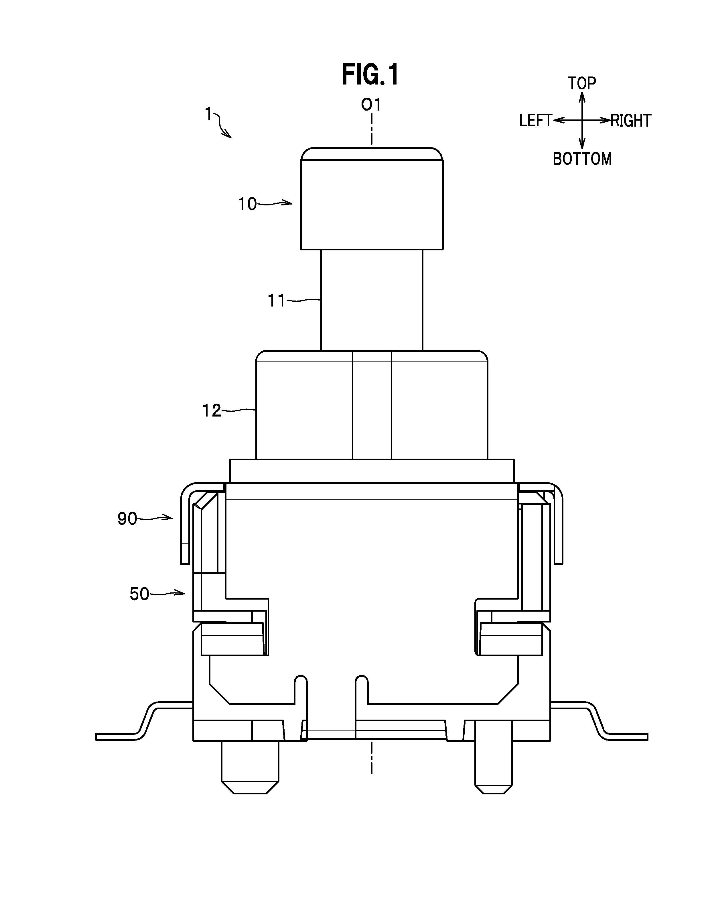
The push switch 1 is a rotary switch, in which pushing the operation button 10 in the direction of axis O1 (axial direction or vertical direction) makes the contact member 30 rotate about the axis O1 relative to the fixed terminal 40 to switch contacts.
The base body 61 represents a shallow square-box shape with the upper opened. Inside of base body 61, the first fixed terminal 41, the second fixed terminal 42, and the third fixed terminal 43 are partially molded.
This application is based upon and claims the benefit of priority from Japanese Patent Application No. 2016-032338 filed on Feb. 23, 2016; the entire contents of which are incorporated herein by reference.