BATTERY PACK
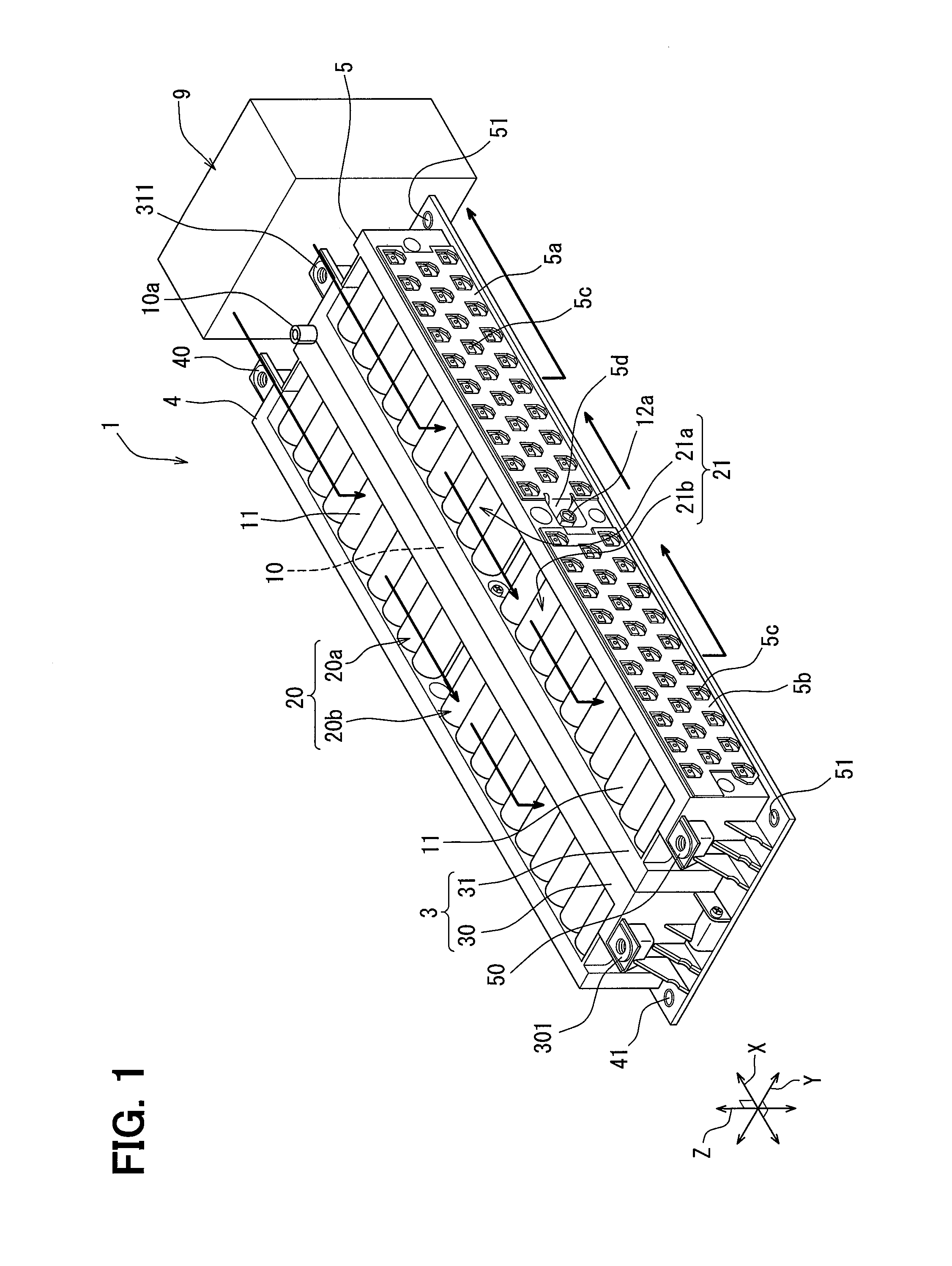
This application is based on and incorporates herein by reference Japanese Patent Application No. 2015-013544 filed on Jan. 27, 2015. The present disclosure relates to a battery pack including multiple battery modules each having multiple battery cells. A battery pack disclosed in Patent Document 1 includes a battery module in which multiple battery cells are electrically connected to each other, a housing that houses the battery module, a partitioning member that covers one side of the battery module to provide multiple exhaust passages, and a lid that covers the partitioning member. In this way, the battery pack has an exhaust passage provided so as to cover the entire one side of one battery module. The exhaust passage is a passage formed for guiding a gas to a predetermined discharge place when an internal pressure of the battery cell rises and the gas inside of the battery cell is ejected. The exhaust passage is shut off from an outside until reaching the predetermined place. One side of the battery module, the partitioning member, and the lid configure an exhaust duct internally having an exhaust passage. In the battery pack of Patent Document 1, there is one exhaust duct that defines an exhaust passage for one battery module. For that reason, in the case of a battery pack including multiple battery modules, there is a need to provide the exhaust duct for each of the battery modules. Further, in order to improve a power storage capacity required for the battery pack, there is a need to increase the number of battery modules in order to increase the number of battery cells. In particular, the requirement is remarkable in the battery packs installed in vehicles requiring a traveling electric power such as electric vehicles, hybrid vehicles and the like. As the number of battery modules increases more, a volume occupied by the exhaust passage in the entire battery pack increases more, which may increase a size of the battery pack. Patent Document 1: JP 2011-070872 A Accordingly, the present disclosure has been made in view of the foregoing points, and an object of the present disclosure is to provide a battery pack capable of reducing a space occupied by an exhaust passage and reducing an overall size of the battery pack. According to an aspect of the present disclosure, a battery pack includes: a plurality of battery modules each of which includes a plurality of battery cells electrically connected to each other, the plurality of battery modules including at least two facing battery modules that face each other; and an exhaust duct disposed between the facing battery modules and integrated with the facing battery modules. Each of the facing battery modules has a gas discharge mechanism provided in the battery cell, and the exhaust duct has therein an exhaust passage that communicates with an outer surface of the gas discharge mechanism. According to the above configuration, the exhaust passage is provided between the facing battery modules, and the outer surfaces of the gas discharge mechanisms of the battery cells of each battery module communicate with the exhaust passage. With the above configuration, when the gas is discharged from any of the battery cells in the facing battery modules, the gas can be discharged to the outside through the exhaust passage between the facing battery modules. In other words, as compared with the battery pack having one exhaust duct for one battery module, an installation space of the battery relative to the entire pack space can be increased. This makes it possible to provide a battery pack that contributes to an improvement in the power storage capacity. As described above, since the space occupied by the exhaust passage can be reduced, a size of the entire battery pack can be reduced against a demand to improve the power storage capacity. A battery pack 1 according to an embodiment of the present disclosure is applied to, for example, hybrid vehicles with the combination of an internal combustion engine with a motor driven by an electric power charged in a battery as a travel driving source, electric vehicles with a motor as the travel driving source, and so on. Multiple battery cells 2 forming a battery pack 1 can be formed of, for example, a nickel-hydrogen secondary battery, a lithium ion secondary battery, or an organic radical battery. The present embodiment will be described with reference to As the battery cells 2 used in the battery pack 1 according to the present embodiment, a lithium ion secondary battery will be described as an example. The battery cell 2 disclosed in the present disclosure includes an electrode body having a positive electrode and a negative electrode, and a battery case that accommodates the electrode body and an electrolytic solution. The battery case for accommodating the electrode body is configured by a cylindrical portion as a case body and a lid. The cylindrical portion has a shape capable of accommodating the electrode body, for example, a bottomed cylindrical shape. The cylindrical portion has an opening portion at an upper portion, and is formed so as to accommodate the electrode body through the opening portion. The lid is a disk-shaped member that closes the upper end opening portion of the cylindrical portion. The battery case is preferably made of a metal material that is lightweight and high in thermal conductivity, such as aluminum, stainless steel, or nickel plated steel. The lid of the battery case is equipped with safety valves 2 Further, positive electrode terminals 2 The battery pack 1 illustrated in As illustrated in The cell support member 30 is a first support member that supports the sub-module 20 As illustrated in The busbar 30 A gap between the battery cell 2 accommodated in each accommodation support portion 306 and the accommodation support portion 306 is sealed with a seal member 317 in a state in which each battery cell 2 included in the battery module 20 is electrically connected to the busbar 30 A cell support member 4 clamps and supports the battery module 20 in cooperation with the cell support member 30. Like the cell support member 30, the cell support member 4 is provided with accommodation support portions corresponding to the positions and the number of the battery cells 2 so as to support the battery cells 2 of the battery module 20. Like the accommodation support portion 306 of the cell support member 30, the accommodation support portion has a concave portion conforming to a shape of an end portion of each battery cell 2 in the axial direction of the battery cell 2, that is, a columnar shape. Each accommodation support portion is provided with a through hole that penetrates a bottom portion of the concave portion like the accommodation support portion 306. The through hole has such a size that a negative electrode terminal 2 The busbar 4 Further, as illustrated in As illustrated in The busbar 31 A gap between the battery cell 2 accommodated in each accommodation support portion 316 and the accommodation support portion 316 is sealed with a seal member 317 in a state in which each battery cell 2 included in the battery module 21 is electrically connected to the busbar 31 A cell support member 5 clamps and supports the battery module 21 in cooperation with the cell support member 31. Like the cell support member 31, the cell support member 5 is provided with accommodation support portions corresponding to the positions and the number of the battery cells 2 so as to support the battery cells 2 of the battery module 21. Like the accommodation support portion 316 of the cell support member 31, the accommodation support portion has a concave portion conforming to a shape of an end portion of each battery cell 2 in the axial direction of the battery cell 2, that is, a columnar shape. Each accommodation support portion is provided with a through hole that penetrates a bottom portion of the concave portion like the accommodation support portion 316. The through hole has such a size that a negative electrode terminal 2 The busbar 5 Further, as illustrated in The exhaust passage 10 having a rectangular parallelepiped shape having a length in the X-direction and a length in the Z-direction corresponding to the battery modules 20 and 21 and is shaped in a flat in the Y-direction is provided in the interior of the exhaust duct 3. The exhaust duct 3 includes a thermal diffusion plate 6 that is interposed between the cell support member 30 and the cell support member 31 in a facing positional relationship to divide the exhaust passage 10 into two pieces in the Y-direction. Further, the thermal diffusion plate 6 is interposed between the accommodation support portion 306 that supports the battery cells 2 of one battery module 20 of the battery modules 20 and 21 having the facing positional relationship and the accommodation support portion 316 that supports the battery cells 2 of the other battery module 21. The thermal diffusion plate 6 is a member having a thermal conductivity, and can be made of, for example, a metal plate. Further, the thermal diffusion plate 6 has a size and shape over the exhaust passage 10 as a whole. The thermal diffusion plate 6 is installed inside of the exhaust duct 3 so as to ensure a predetermined distance from each of the busbars 30 The battery pack 1 is controlled by electronic components used for charging and discharging the multiple battery cells 2 or regulating the temperature. The electronic components include, for example, a DC/DC converter, a motor for driving an air blowing member, an electronic component controlled by an inverter, various electronic control devices and the like. For example, the electronic components are portions activated by an electric power regulated by a power element which is a switching power supply device. The battery pack 1 has the cell mounting chamber 11 in which the battery modules 20 and 21 are accommodated. A temperature control fluid is circulated in the cell mounting chamber 11 by a fluid drive device 9 that drives a predetermined temperature control fluid. The exhaust duct 3 has a function of separating the cell mounting chamber 11 and the exhaust passage 10 as separate spaces. Therefore, the exhaust duct 3 does not allow the temperature control fluid to flow into the exhaust passage 10, but functions to prevent the gas ejected from each battery cell 2 from flowing into the cell mounting chamber 11 by unsealing the corresponding safety valve 2 As illustrated in In the battery pack 1, the case for accommodating the battery modules 20 and 21 is formed by the exhaust duct 3 and the cell support member 4 and the cell support member 5 which are arranged on both sides of the exhaust duct 3 in the Y-direction. The case is a rectangular parallelepiped case opened at upper and lower end portions of the case, and an opening portion at the upper end and an opening portion at the lower end configure an inflow port and an outflow port of the temperature control fluid in the cell mounting chamber 11. Further, the case is made of a material having an electrical insulation property, for example, a resin material. The case is equipped with four attachment portions 41 and 51 for fixing a housing to the vehicle side by bolting or the like, and may be provided integrally with an equipment storage box. For example, a battery monitoring unit that receives detection results of a voltage, a temperature, and so on from various sensors, a control device that can communicate with the battery monitoring unit and exchanges a power with a DC/DC converter and controls the fluid drive device 9, a wire harness that connects the various equipments to each other, and so on are accommodated in the equipment box. The battery monitoring unit is a battery electronic control unit that monitors a state of each battery cell 2 and is connected to the battery pack 1 by a large number of wirings. Subsequently, the assembly of the battery pack 1 will be described with reference to In this step, each of the battery cells 2 of the sub-module 20 More specifically, screw tightening is performed at a total of three places, including one at each end portion of the assemble in the longitudinal direction and one at the center in the longitudinal direction, and the battery module 20 is fixedly sandwiched between the cell support member 4 and the cell support member 30. One screw 14 is passed through a screw through hole 42 provided at one end portion of the cell support member 4 in the longitudinal direction and screwed into a screw hole 302 provided in the cell support member 30. Further, in the cell support member 4, the other screw 14 is passed through the other screw through hole 42 provided at an opposite end portion in the longitudinal direction and is screwed into the other screw hole 302 provided in the cell support member 30. Further, in the cell support member 4, a screw 15 is passed through a screw through hole 43 provided in a center in the longitudinal direction and is screwed into a screw hole 303 provided in the cell support member 30. The screws are fastened at those three positions, to thereby narrow a space between the cell support member 4 and the cell support member 30. As a result, the battery module 20 can be clamped and fixed integrally with the cell support member 4 and the cell support member 30. Further, a bolt 13 Also, the assembly of the cell support member 31, the battery module 21, the cell support member 5, and the cover 7 can be carried out similarly. More specifically, the busbar 31 Further, screw tightening is performed at a total of three places, including one at each end portion of the assemble in the longitudinal direction and one at the center in the longitudinal direction, and the battery module 21 is fixedly sandwiched between the cell support member 5 and the cell support member 31. One screw is passed through a screw through hole 52 provided at one end portion of the cell support member 5 in the longitudinal direction and screwed into a screw hole provided in the cell support member 31. Further, in the cell support member 5, the other screw is passed through the other screw through hole 52 provided at an opposite end portion in the longitudinal direction and is screwed into the other screw hole provided in the cell support member 31. Further, in the cell support member 5, a screw is passed through a screw through hole provided in a center in the longitudinal direction and is screwed into a screw hole provided in the cell support member 31. The screws are fastened at those three positions, to thereby narrow a space between the cell support member 5 and the cell support member 31. As a result, the battery module 21 can be clamped and fixed integrally with the cell support member 5 and the cell support member 31. Further, a bolt is passed through a threaded through hole provided in the end portion 5 Next, First, from a state in which the cell support member 30 in the first sub-unit faces the cell support member 31 in the second sub-unit and the thermal diffusion plate 6 is disposed between the cell support member 30 and the cell support member 31, the cell support member 30 and the cell support member 31 are combined together. Further, a screw 16 is passed through a screw through hole 314 provided at each end portion of the cell support member 31 in the longitudinal direction and is screwed into a screw hole 304 provided in the cell support member 30. Further, in the cell support member 5, a screw 17 is passed through a screw through hole 55 provided in a center in the longitudinal direction and a screw through hole provided in the thermal diffusion plate 6 and is screwed into a screw hole 305 provided in the cell support member 30. The first sub-unit and the second sub-unit can be fixed integrally with each other by tightening the screws at these three places. Finally, a cover 8 for electrical insulation is attached to the cell support member 5 so as to cover the busbars 5 According to the above embodiment, the battery pack 1 includes the multiple battery modules 20 and 21 each having the multiple battery cells 2, and the exhaust duct 3 that is provided integrally with the battery module between at least the two battery modules 20 and 21 in a facing positional relationship. The exhaust duct 3 is internally provided integrally with the exhaust passage 10 that communicates with an outer surface of the safety valve 2 According to the above configuration, the exhaust passage 10 is provided between at least two opposing battery modules 20 and 21, and the outer surfaces of the gas discharge mechanisms of the battery cells 2 in each of the battery modules 20 and 21 communicate with the exhaust passage 10. With the above configuration, when the gas is discharged from any of the battery cells 2 in at least two battery modules 20 and 21 having the facing relationship, the gas can be discharged to the outside through the exhaust passage 10 located between those battery modules 20 and 21. In other words, as compared with the battery pack having one exhaust duct for one battery module, an installation space of the secondary battery relative to the entire pack can be increased. In other words, because a smoke exhaust duct can be integrated with the two battery modules in the battery pack 1, a space for exhaust duct in the battery pack 1 can be saved. With the above configuration, since the space occupied by the exhaust passage 10 can be reduced, the battery pack 1 reduced in an overall size can be provided against a demand to improve a power storage capacity. Further, the exhaust duct 3 has accommodation support portions 306 and 316 that accommodate and support at least the end portion 2 According to this configuration, in the exhaust duct 3, a part for supporting each cell and a part for ejecting the gas can be provided in one portion. Therefore, the battery pack 1 provided with the exhaust duct 3 having both of the function as the exhaust duct 3 and the function of holding and positioning the multiple battery cells 2 can be provided. According to the above configuration, the exhaust duct 3 that reduces the number of components, has the multiple functions, and is compact can be provided. Further, the exhaust duct 3 includes the first support member for supporting the battery module 20 located on one side of the facing battery modules 20 and 21, and the second support member for supporting the battery module 21 located on the other side. The exhaust passage 10 is a passage provided inside of the assembly in which the first support member and the second support member are combined with each other face to face. According to the above configuration, the assembly in which the support portions of the cells and the gas exhaust passage can be integrally configured can be provided. With the provision of the assembly, a space for forming the support portions of the cell and the exhaust passage can be reduced and the mounting efficiency of the battery cells 2 in the battery pack 1 can be improved. Further, the first support member has the accommodation support portion 306 that accommodates and supports at least the end portion of each battery cell 2 in the battery module 20. Further, the second support member has the accommodation support portion 316 that accommodates and supports at least the end portion of each battery cell 2 in the battery module 21. The through hole 306 According to the above configuration, in the first support member and the second support member, the part for supporting the cells and the part for ejecting the gas can be provided in one portion. Therefore, the battery pack 1 in which members having both of the function of the exhaust duct 3 and the function of holding and positioning the multiple battery cells 2 are combined together can be provided. According to the above configuration, the first support member and the second support member having the multiple functions and being compact can be provided. Further, the busbars 30 According to the above configuration, the members for fixing the busbars, the members for supporting the cells, and the members for providing the exhaust passage 10 can be configured by one member. Therefore, the battery pack 1 having a member having all of the cell support function, the function as the exhaust duct 3 for discharging the gas, and the function for realizing an electric connection of the multiple battery cells 2 can be provided. Further, the battery pack 1 has a separation structure for separating a portion for fixing the busbars and a portion for supporting the cells from each other on both sides of the first support member and the second support member. According to the above configuration, the battery pack 1 that can provide the member forming the exhaust duct 3 with the multiple functions, and effectively utilizes a space occupied by the exhaust duct 3 can be obtained. Further, the exhaust duct 3 partitions the cell mounting chamber 11 where the battery modules 20 and 21 to be supported are installed, and the exhaust passage 10 as separate spaces. A temperature control fluid that comes in contact with the battery modules 20 and 21 flows in the cell mounting chamber 11. A gap between the battery cells 2 accommodated in the accommodation support portions 306 and 316 and the accommodation support portions 306 and 316 is sealed with the seal member 317. According to the above configuration, when the gas is ejected from the inside of the battery cell 2 to the exhaust passage 10, the gas can be prevented from flowing out to the cell mounting chamber 11. Therefore, the battery pack 1 capable of blocking a communication between a room through which the temperature control fluid flows and the passage through which a flue gas flows with the compact size is obtained. The exhaust duct 3 includes therein the thermal diffusion plate 6 having a thermal conductivity which is interposed between the accommodation support portion 306 supporting the battery module 20 and the accommodation support portion 316 supporting the second battery module 21 in the facing battery modules 20 and 21, and the thermal diffusion plate 6 separates the exhaust passage into two passages. According to the above configuration, for example, when a gas is discharged from one of the battery modules, the gas can be restrained from flowing out to the other battery module side by the thermal diffusion plate 6 functioning as a partitioning member. As a result, a chain-like gas ejection and an influence on the peripheral components associated with the gas ejection at one place can be suppressed. In addition, since a thermal diffusion occurs due to the thermal conductivity of the thermal diffusion plate 6, the occurrence of a local high temperature portion can be suppressed, which contributes to a suppression of the deterioration of the local component and the like. In addition, the exhaust duct 3 has a single exhaust outlet port 10 The preferred embodiment of the present disclosure has been described above, but this disclosure is not limited to the above-mentioned embodiment at all and can be modified without departing from the gist of this disclosure. The structures of the embodiment are merely illustrative, and the scope of the present disclosure is not limited to the range of the description of the structures. In the embodiment described above, the battery cells configuring each battery module can also be configured by a single cell having a prismatic exterior case made of metal. The rectangular single cell is a flat rectangular parallelepiped whose outer peripheral surface is covered with an outer case made of, for example, aluminum, an aluminum alloy or the like. In the rectangular parallelepiped battery cell, a predetermined electrode terminal is connected to the busbar, and the safety valve to which the gas is ejected due to an increase in internal pressure is located in correspondence with the opening portions of the first support member providing the exhaust duct and is supported by the first support member. The number of battery modules included in the battery pack according to the present disclosure is not limited to the number disclosed in the above-described embodiment. In addition, one exhaust duct of the battery pack is provided for at least two battery modules installed so that the safety valves face each other. Further, one battery pack may include the multiple exhaust ducts provided in at least two battery modules. In the above embodiment, grooves or protrusions of labyrinthine or spiral structure may be provided on an inner surface of the accommodation support portion 306 and the accommodation support portion 316. In the above embodiment, the fluid drive device for forcibly feeding the temperature control fluid to the fluid passage may be of a type in which the temperature control fluid is drawn into the fluid passage, or a type in which the temperature control fluid is pushed into the fluid passage. While the present disclosure has been described with reference to embodiments thereof, it is to be understood that the disclosure is not limited to the embodiments and constructions. To the contrary, the present disclosure is intended to cover various modification and equivalent arrangements. In addition, while the various elements are shown in various combinations and configurations, which are exemplary, other combinations and configurations, including more, less or only a single element, are also within the spirit and scope of the present disclosure. A battery pack includes multiple sub-modules each of which includes multiple battery cells electrically connected to each other, and an exhaust duct that is provided between and integrated with at least the two battery modules facing each other. The exhaust duct includes therein an exhaust passage that communicates with an outer surface of a safety valve provided in each battery cell in each of the facing battery modules. 1. A battery pack comprising:
a plurality of battery modules each of which includes a plurality of battery cells electrically connected to each other, the plurality of battery modules including at least two facing battery modules that face each other; and an exhaust duct disposed between the facing battery modules and integrated with the facing battery modules, wherein each of the facing battery modules has a gas discharge mechanism provided in the battery cell, and the exhaust duct has therein an exhaust passage that communicates with an outer surface of the gas discharge mechanism. 2. The battery pack according to the exhaust duct includes accommodation support portions that accommodate and support at least respective end portions of the battery cells of the facing battery modules, and each of the accommodation support portions includes a through hole through which the outer surface of the gas discharge mechanism is exposed to the exhaust passage. 3. The battery pack according to the facing battery modules include a first battery module and a second battery module that faces the first battery module, the exhaust duct includes a first support member that supports the first battery module and a second support member that supports the second battery module, and the exhaust passage is provided inside of an assembly in which the first support member and the second support member are combined to face each other. 4. The battery pack according to the first support member includes accommodation support portions that accommodate and support at least the respective end portions of the battery cells of the first battery module, the second support member includes accommodation support portions that accommodate and support at least the respective end portions of the battery cells of the second battery module, and each of the accommodation support portions includes a through hole through which the outer surface of the gas discharge mechanism is exposed to the exhaust passage. 5. The battery pack according to the first support member is integrally fixed to a busbar that electrically connects the plurality of battery cells of the first battery module to each other, and the second support member is integrally fixed to a busbar that connects the plurality of battery cells of the second battery module to each other. 6. The battery pack according to a cell mounting chamber in which the facing battery modules are located and through which a temperature control fluid flows with being in contact with the facing battery modules flows; and a seal member that seals a gap between the battery cell accommodated in each of the accommodation support portions and the each accommodation support portion, wherein the cell mounting chamber and the exhaust passage are divided by the exhaust duct from each other as separate spaces. 7. The battery pack according to the facing battery modules include a first battery module and a second battery module that faces the first battery module, and the exhaust duct includes therein a thermal diffusion plate having a thermal conductivity and interposed between the accommodation support portion supporting the first battery module and the accommodation support portion supporting the second battery module, and the thermal diffusion plate separates the exhaust passage into two passages. 8. The battery pack according to the exhaust duct includes therein a thermal diffusion plate having a thermal conductivity and interposed between the accommodation support portion supporting the first battery module and the accommodation support portion supporting the second battery module, and the thermal diffusion plate separates the exhaust passage into two passages. 9. The battery pack according to the exhaust duct has a single exhaust outlet port through which the exhaust passage communicates with an outside.CROSS REFERENCE TO RELATED APPLICATION
TECHNICAL FIELD
BACKGROUND ART
PRIOR ART DOCUMENT
Patent Document
SUMMARY
BRIEF DESCRIPTION OF THE DRAWINGS
DESCRIPTION OF EMBODIMENTS