BAR AND PLATE AIR-OIL HEAT EXCHANGER
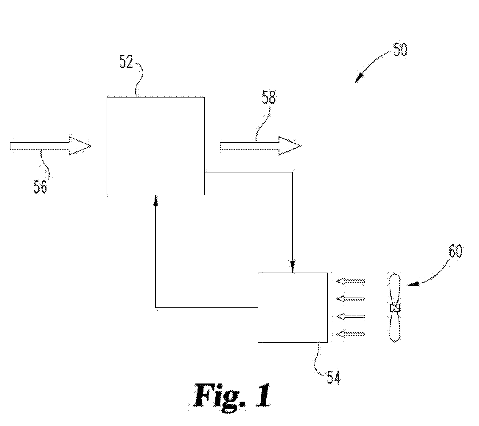
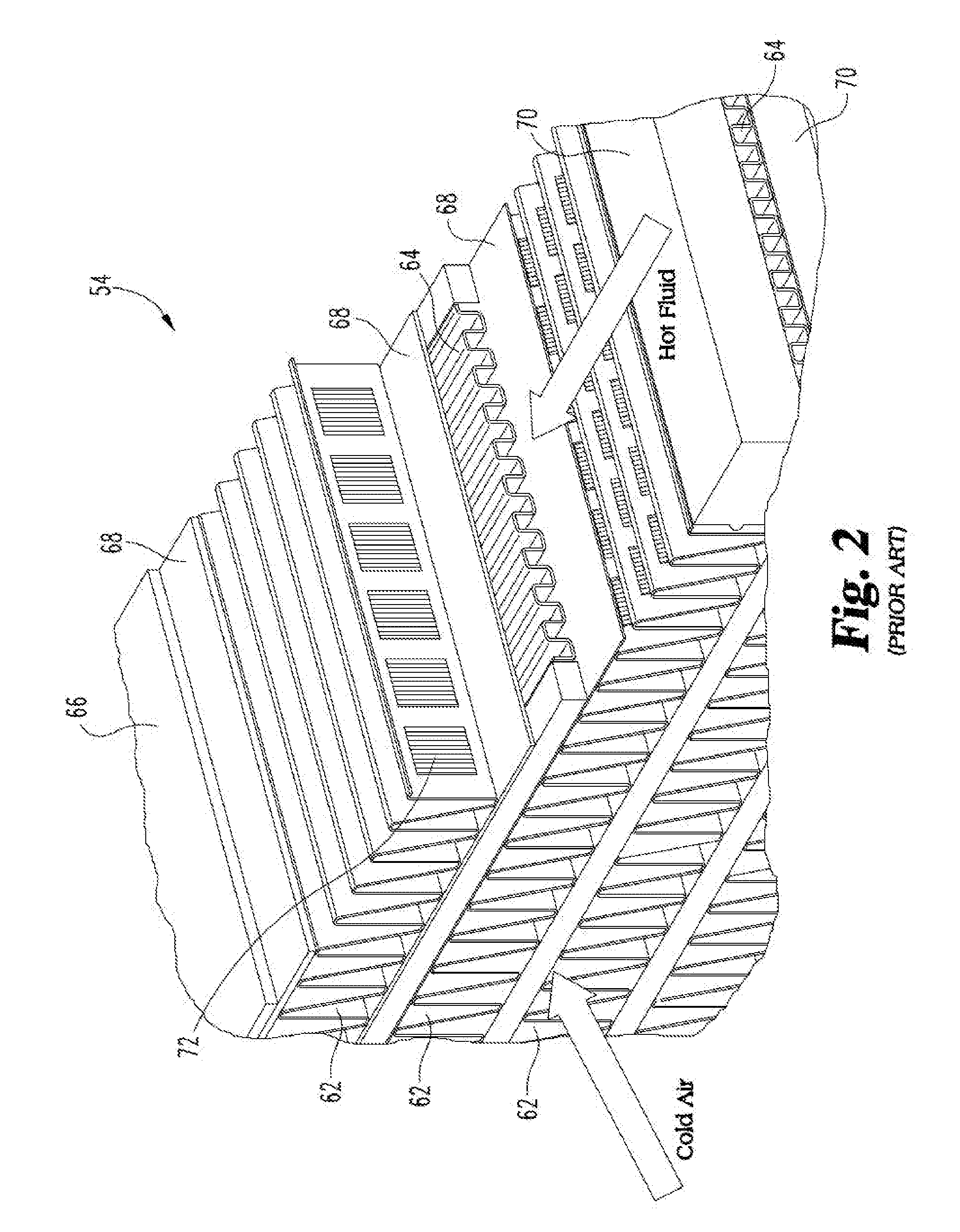
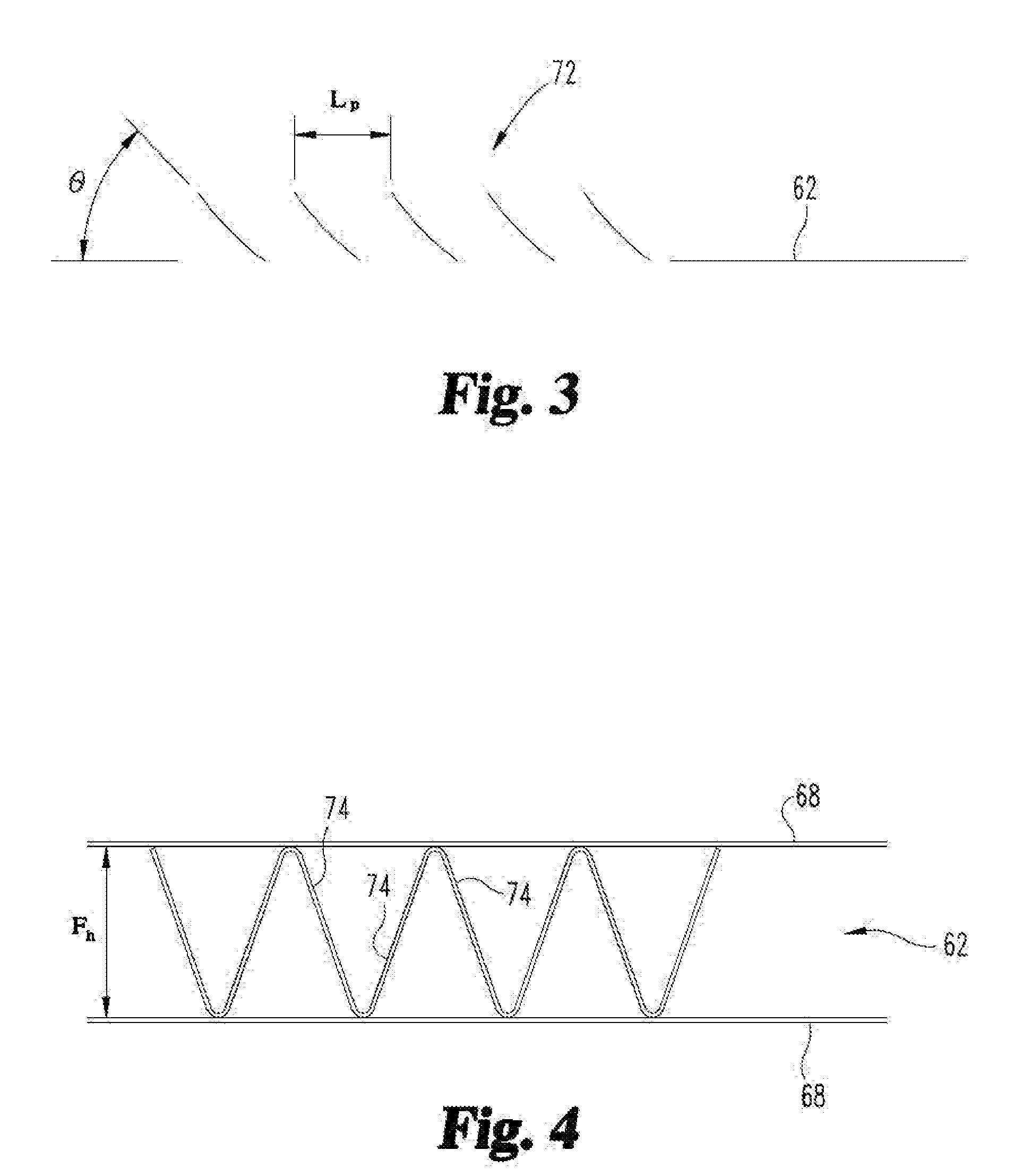
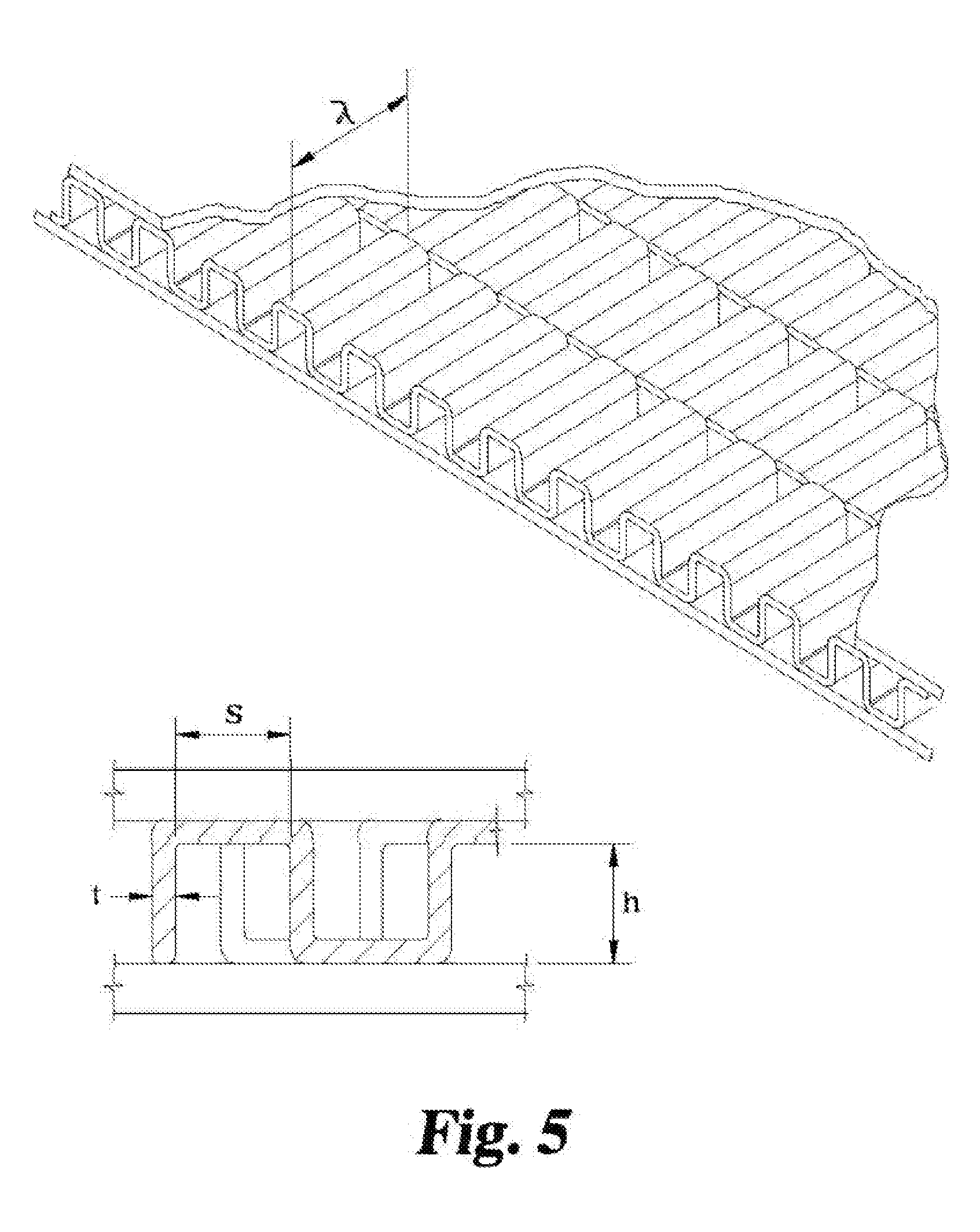
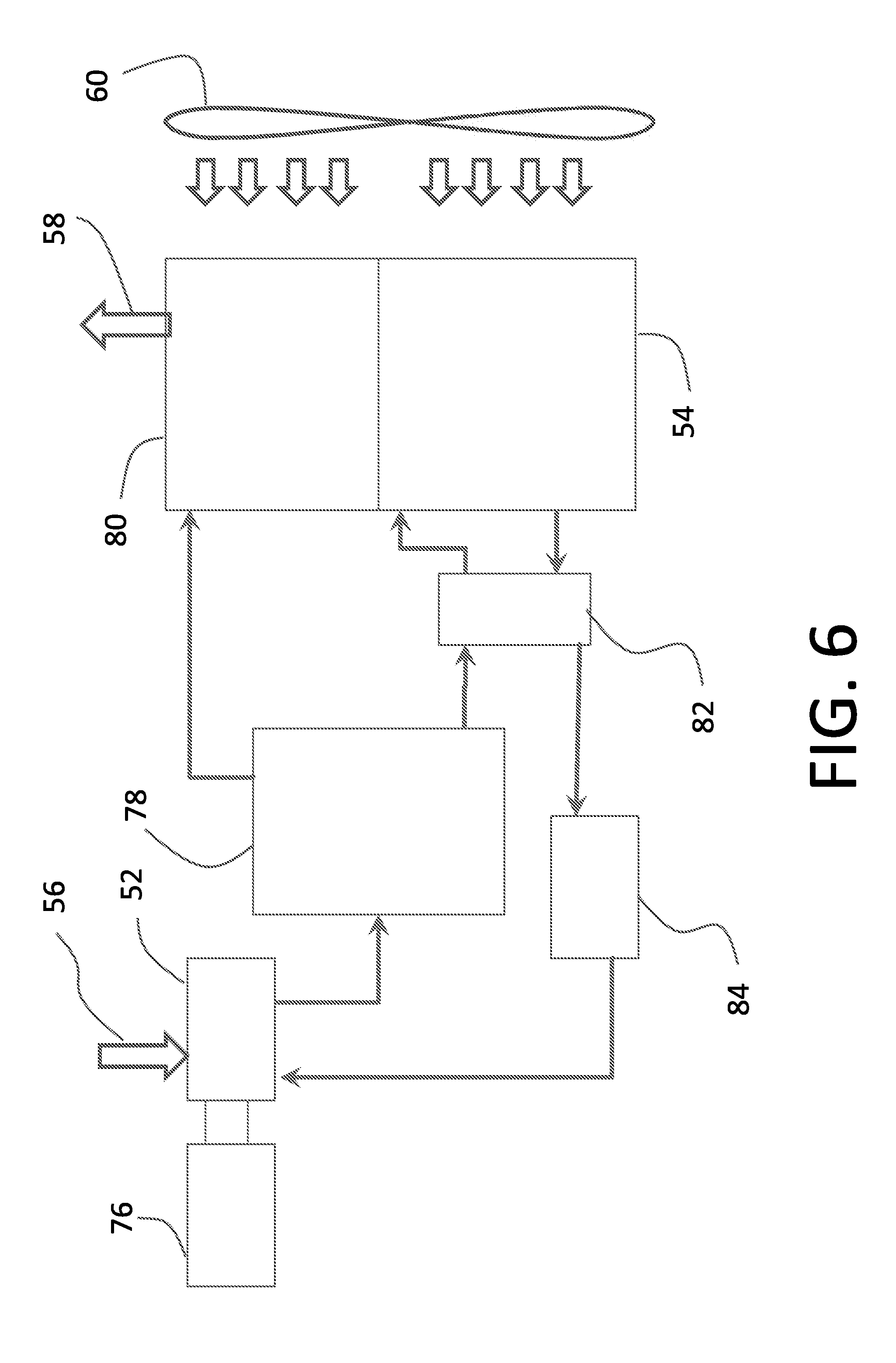
The present invention generally relates to compression system heat exchangers, and more particularly, but not exclusively, to particular arrangement of bar and plate heat exchanger. Providing improvements in bar and plate heat exchangers used in compression systems remains an area of interest. Some existing systems have various shortcomings relative to certain applications. Accordingly, there remains a need for further contributions in this area of technology. One embodiment of the present invention is a unique heat exchanger for use with a compression system. Other embodiments include apparatuses, systems, devices, hardware, methods, and combinations for reduced pressure loss and low weight heat exchangers. Further embodiments, forms, features, aspects, benefits, and advantages of the present application shall become apparent from the description and figures provided herewith. For the purposes of promoting an understanding of the principles of the invention, reference will now be made to the embodiments illustrated in the drawings and specific language will be used to describe the same. It will nevertheless be understood that no limitation of the scope of the invention is thereby intended. Any alterations and further modifications in the described embodiments, and any further applications of the principles of the invention as described herein are contemplated as would normally occur to one skilled in the art to which the invention relates. With reference to The oil cooler 54 is used to cool oil or other fluid used in conjunction with operation of the compressor 52. The oil, or other suitable fluid, can be used for lubrication and cooling purposes within the compressor 52, among other uses. The oil cooler 52 can structured as an air-oil heat exchanger and in the illustrated embodiment includes a fan 60 or other suitable fluid moving devices which provides a stream of moving air useful in exchanging heat with oil routed through the oil cooler 54. Yet another embodiment is shown in A prior art embodiment of an oil cooler is shown in The external fins 62 can be formed of any heat conductive material, and can be triangular shaped as illustrated in Turning now to The external fins 62 and/or the internal fins 64 can be made using a variety of approaches, which include forming a unitary member, coupling separate components together to form the member, etc. To set forth just a few examples, the external fins 62 can be stamped into shape to form the triangular shape as depicted in the illustrated embodiment. The offset strip type of the internal fins 64 as illustrated can include a number of separate strips that are individually stamped, which are then brought together in an offset configuration before being consolidated into an internal fin construction. It will be appreciated that in highly complex, multi-variate systems, it is not always clear which combination of parameters provide for improvements. The instant application has discovered heretofore unappreciated arrangement of multiple and unrelated components in the heat exchanger 54 which unexpectedly provided for an appreciable degree in reduced pressure loss and weight. Prior to their discovery as disclosed in the instant application, it was unknown which combination and degree of factors in the aggregate provided the best solution. As a result of the inventive concepts described herein, it was discovered that at least one potential candidate, internal strip length, was deemed to either not impact the overall study or minimally impact the study, while other parameters were changed quite significantly from the conventional baseline indicating that the state of the art was unaware of the combination and degree of changes required to provide a better solution. The combination of parameters that have led to unexpected improvements are as follows (listing the known baseline prior system for comparison): The dimensions quoted herein regarding various geometries of the heat exchanger need not always be precisely exact as is well understood. Manufacturing tolerances permit some degree of dimensional variation. Of the parameters listed above, the first four listed in the chart (external fin height, internal fin height, internal fin pitch, and external fin per inch) where surprisingly found to be most important in achieving the desired objectives, while the remaining parameters (internal strip length, external louver angle, and external louver pitch) were deemed to be less important. The arrangement of components as described above was determined assuming that a core face area of 15.39 square feet, core depth of 6 inches, blower air flow of 14,145 cubic feet per minute, air inlet temperature of 120 degrees F., oil inlet temperature of 212 degrees F., and an oil flow rate of 42,900 lb/hr. It is possible to construct a heat exchanger using values that are between the numbers listed above in Option 1 and Option 2, which will provide for a tradeoff between low pressure loss and low weight. The oil cooler 54 embodiments disclosed herein could be used for an air-to-air heat exchanger as well, such as might be used in interstage cooling of a multi-stage compressor system, or as an aftercooler in other embodiments, to set forth just a few non-limiting examples. While the invention has been illustrated and described in detail in the drawings and foregoing description, the same is to be considered as illustrative and not restrictive in character, it being understood that only the preferred embodiments have been shown and described and that all changes and modifications that come within the spirit of the inventions are desired to be protected. It should be understood that while the use of words such as preferable, preferably, preferred or more preferred utilized in the description above indicate that the feature so described may be more desirable, it nonetheless may not be necessary and embodiments lacking the same may be contemplated as within the scope of the invention, the scope being defined by the claims that follow. In reading the claims, it is intended that when words such as “a,” “an,” “at least one,” or “at least one portion” are used there is no intention to limit the claim to only one item unless specifically stated to the contrary in the claim. When the language “at least a portion” and/or “a portion” is used the item can include a portion and/or the entire item unless specifically stated to the contrary. Unless specified or limited otherwise, the terms “mounted,” “connected,” “supported,” and “coupled” and variations thereof are used broadly and encompass both direct and indirect mountings, connections, supports, and couplings. Further, “connected” and “coupled” are not restricted to physical or mechanical connections or couplings. An air-oil heat exchanger used in a compression system that includes a compressor is disclosed. The heat exchanger can be used to cool oil in one embodiment which is used in a compression process. The heat exchanger can be a bar-and-plate type heat exchanger having a number of external fins, internal fins, parting sheets, and header bars. The external fins can include louvers formed therein. An arrangement of multiple unrelated components can be provided that improves pressure loss and reduces weight. 1. An apparatus comprising:
a bar and plate heat exchanger having an arrangement of external fins disposed in a first flow path separated from an arrangement of internal fins disposed in a second flow path by a parting sheet, the first flow path distinct from the second flow path, wherein the arrangement of external fins and the arrangement of internal fins are structured according to the following: external fin height of about 0.438″; internal fin height of about 0.098″; internal fin pitch of about 0.069″; and external fin per inch of about 11. 2. The apparatus of 3. The apparatus of 4. The apparatus of 5. The apparatus of 6. The apparatus of 7. The apparatus of 8. An apparatus comprising:
a compressor system heat exchanger having a first external fin construction fluidly separated from a first internal fin construction by a parting sheet, wherein the arrangement of external fins and the arrangement of internal fins are structured according to the following: external fin height of about 0.488″; internal fin height of about 0.1″; and internal fin pitch of about 0.081″. 9. The apparatus of 10. The apparatus of 11. The apparatus of 12. The apparatus of 13. The apparatus of 14. The apparatus of 15. The apparatus of 16. An apparatus comprising:
a heat exchanger of the bar and plate type for use with an air compressor system includes an plurality of external fins and a plurality of internal fins, and a parting plate disposed between the external fin device and the internal fin device, the parting plate separating a first flow path in which the external fin device is disposed and a second flow path in which the internal fin device is disposed, the external fin device and the internal fin device having an arrangement as follows: external fin height between about 0.438″ and about 0.488″; internal fin height between about 0.098″ and about 0.100″; internal fin pitch between about 0.069″ and about 0.081″; external fin per inch of between 11 and 12; and internal strip length of about 0.14″. 17. The apparatus of 18. The apparatus of 19. The apparatus of 20. The apparatus of TECHNICAL FIELD
BACKGROUND
SUMMARY
BRIEF DESCRIPTION OF THE FIGURES
DETAILED DESCRIPTION OF THE ILLUSTRATIVE EMBODIMENTS
External FIN HEIGHT 0.375 0.438 0.488 Internal FIN HEIGHT 0.125 0.098 0.100 Internal FIN PITCH 0.074 0.069 0.081 External FIN PER INCH 12 11 12 Internal strip length 0.14 0.14 0.14 External LOUVER ANGLE 23.0 25.2 23.5 External LOUVER PITCH 0.045 0.035 0.035 Output Air side pr. Drop (Pa) 493.7 386.5 430.7 Heat transfer (W) 251317 253002 252603 Oil outlet temperature 76.0 75.8 75.9 (deg C.) Coil weight (Kg) 105.0 89.6 85.9 Oil side pr. Drop (Pa) 38895 56993 50198