LIQUID BLOW MOLDING APPARATUS
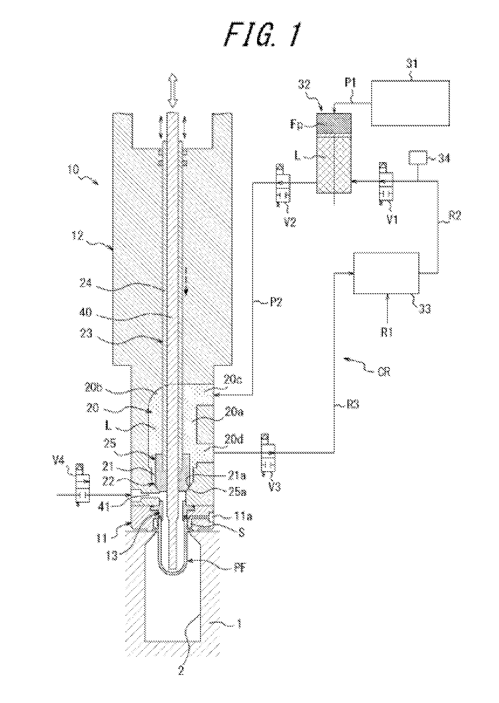
The present invention relates to a liquid blow-molding apparatus for liquid blow-molding a thermoplastic synthetic resin preform into a container of a specific shape. Containers made of synthetic resins, exemplified by polypropylene (PP) bottles and polyethylene terephthalate (PET) bottles, are used to hold various liquids, such as beverages, cosmetics, chemicals, detergents, and shampoos. Such containers are generally manufactured by heating a preform, obtained by molding a thermoplastic resin material into a closed-bottom cylindrical shape, to a temperature at which thermoplasticity manifests, and using a blow molding apparatus to blow mold the preform in this state. One known apparatus for blow molding a preform is a liquid blow-molding apparatus, which comprises a blow molding die in which a preform is disposed, a blow nozzle that engages with a mouth of the preform disposed in the blow molding die, and a pressurized liquid feed unit for feeding pressurized liquid to the blow nozzle, wherein pressurized liquid is fed from the pressurized liquid feed unit through the blow nozzle into the interior of the preform, thereby liquid blow-molding the preform into a container of a specific shape. In accordance with such a liquid blow-molding apparatus, a liquid to be contained in the container as part of the final product, such as a beverage, can be used as the liquid fed to the preform in order to eliminate the need for a post-molding step of filling the container with the liquid, thereby simplifying the production process and the configuration of the liquid blow-molding apparatus. However, as liquids have a higher rate of thermal conductivity with respect to the heated preform than gases, variations in the temperature of the liquid fed to the preform when performing liquid blow molding using the liquid blow-molding apparatus will cause the temperature of the preform to vary as well, thereby problematically reducing the moldability of the container and negatively affecting the capabilities, such as strength and heat resistance, of the molded container. Thus, in the liquid blow-molding apparatus disclosed in Unexamined Japanese Patent Application Publication No. 2013 154617, for example, a feed path connected to the pressurized liquid feed unit is formed in the support block, a blow nozzle connected to the feed path is provided at a lower end of the support block, a valve mechanism is provided between the feed path and the blow nozzle, the valve mechanism is closed in order to circulate a liquid between the pressurized liquid feed unit and the feed path while adjusting the liquid blow-molding apparatus to a specific temperature, and liquid blow molding can be performed by opening the valve mechanism to feed the liquid having been adjusted to the specific temperature to the preform, thereby improving the moldability of the container. However, if, for example, a premade product is used to manufacture the support block of the conventional liquid blow-molding apparatus described above, stepped sections or raised/recessed shapes may be formed in the feed path, so that the feed path comprises multiple air pockets (locations where air tends to accumulate) in its interior. In such cases, air accumulated in the air pockets is fed into the preform along with the liquid, thereby potentially reducing the moldability of the container. Moreover, when the valve mechanism is closed and the liquid is circulated, stagnant pools of liquid form in the air pockets, thereby potentially reducing precision in adjusting the temperature of the circulating liquid and reducing container moldability. While it is conceivable to provide air release valves at the air pockets in the feed path, such an arrangement results in an oversized, expensive apparatus, and is incapable of solving the problem of pooling liquid. The present invention was developed in view of these problems, and, in one aspect, inexpensively provides a liquid blow-molding apparatus that is capable of precisely molding a container without air pockets or liquid pooling occurring in the liquid feed path. The liquid blow-molding apparatus according to the principles of the present invention is a liquid blow-molding apparatus provided with: a blow molding die in which is disposed a closed-bottom cylindrical preform, a support block disposed above the blow molding die and having a feed path formed in its interior, a blow nozzle that is provided at a lower end of the support block continuously with the feed path and that engages with a mouth of a preform disposed in the blow molding die, and a pressurized liquid feed unit connected to the feed path, pressurized liquid being fed from the pressurized liquid feed unit through the blow nozzle into the interior of the preform to liquid blow-mold the preform into a shape conforming to a cavity of the blow molding die; the apparatus being characterized in that the feed path has a shape comprising a flow path body having a vertically extending inner diameter that is constant or decreases toward the blow nozzle, a dome chamber that is formed in a domed shape and is continuous with an upper end of the flow path body, a first port that has the same upper end as the dome chamber and which extends horizontally from the dome chamber, and a second port connected to the flow path body; a valve mechanism for opening and closing an open-and-closable flow path connecting the flow path body and the blow nozzle is provided in the open-and-closable flow path; and a liquid circulates between the feed path and the pressurized liquid feed unit when the valve mechanism is in a closed state, and pressurized liquid being fed from the feed path through the blow nozzle into the interior of the preform when the valve mechanism is in an open state. In the liquid blow-molding apparatus according to the principles of the present invention, the first port and the second port preferably communicate via a liquid circulation section in which the pressurized liquid feed unit and the liquid are adjusted to a specific temperature. In the liquid blow-molding apparatus according to the principles of the present invention, an air release valve is preferably provided at a site at the highest location of a circulation path leading from the pressurized liquid feed unit through the feed path and the liquid circulation section back to the pressurized liquid feed unit. In the liquid blow-molding apparatus according to the principles of the present invention, it is preferable that a rod-shaped seal pin that passes through the flow path body and is capable of movement in the vertical direction be provided in the support block, the valve mechanism being placed into a closed state by a lower end of the seal pin contacting a seal part provided in the open-and-closable flow path, and into an open state by the lower end of the seal pin rising upward away from the seal part. In the liquid blow-molding apparatus according to the principles of the present invention, the seal pin preferably comprises a rod slideably inserted in a liquid-tight state into a tubular housing. In accordance with the principles of the present invention, it is possible to prevent the formation of air pockets within the feed path and prevent pooling of the liquid flowing through the feed path without the need to provide multiple air-release valves in the feed path. This results in an arrangement in which the liquid used as the pressurized fluid is circulated between the pressurized liquid feed unit and the feed path, wherein penetration of air into the liquid being fed from the feed path is prevented, and precision in adjusting the temperature of the liquid is increased, thereby enabling precise liquid blow molding of the container. In this way, it is possible, in accordance with the principles of the present invention, to inexpensively provide a liquid blow-molding apparatus that is capable of precisely molding a container without air pockets or liquid pooling occurring in the liquid feed path. The present invention will now be described in greater detail with reference to the drawings. First, the overall configuration of a liquid blow-molding apparatus according to an embodiment incorporating the principles of the present invention will be described with reference to As shown in The preform PF is set in the blow molding die 1. As illustrated in A nozzle unit 10 that is capable of relative motion in the vertical direction with respect to the blow molding die 1 is provided above the blow molding die 1. The nozzle unit 10 is provided with a retaining member 11, a support block 12, and a blow nozzle 13. As illustrated in A space S surrounding the outer circumferential surface of the mouth PFb of the preform PF set in the blow molding die 1 and the inner circumferential surface of the retaining member 11 is defined therebetween, and an air hole 11 The support block 12 is formed from steel, for example, in a cylindrical shape in the interior of which is formed a feed path 20, is anchored to the upper end of the retaining member 11, and is capable of relative vertical movement along with the retaining member 11 with respect to the blow molding die 1. As illustrated in An open-and-closable flow path 21 coaxially continuous with the lower end of the flow path body 20 The blow nozzle 13 is attached to the lower end of the support block 12, and is sandwiched between the retaining member 11 and the support block 12. The blow nozzle 13 is formed in an overall cylindrical shape, and an opening in the upper end thereof is continuous with the open-and-closable flow path 21. In other words, the blow nozzle 13 is continuous with the feed path 20 through the open-and-closable flow path 21. When the nozzle unit 10 is lowered to a lower end position, as illustrated in A valve mechanism 22 for opening and closing the open-and-closable flow path 21 is provided in the open-and-closable flow path 21. The valve mechanism 22 is provided with a rod-shaped seal pin 23, provided in the support block 12, that passes through the axial center of the flow path body 20 As illustrated in The pressurization device 31 is constituted, for example, by a pressurization pump, compressor, or the like, and is connected to the pressurized liquid feed unit 32 via a conduit P1. The pressurized liquid feed unit 32 can be constituted by, for example, a plunger pump or piston-cylinder mechanism, and is configured so as to be operated by pressurized fluid Fp fed from the pressurization device 31. The pressurized liquid feed unit 32 is connected to the first port 20 The liquid circulation section 33 has a function of adjusting the liquid L to a specific temperature while receiving fresh liquid L from a conduit R1, feeding the liquid L to the pressurized liquid feed unit 32 via a conduit R2, and circulating the liquid L between the pressurized liquid feed unit 32 and the feed path 20 while adjusting the liquid to the specific temperature. Specifically, the liquid circulation section 33 is connected to the second port 20 By virtue of such an arrangement, when the open-and-closable flow path 21 is closed by the valve mechanism 22, the liquid L is capable of circulating between the pressurized liquid feed unit 32 and the feed path 20 via a circulation path CR leading from the flow path body 20 Three solenoid valves V1, V2, V3 are provided along the circulation path CR, and, when the open-and-closable flow path 21 is closed by the valve mechanism 22 and the liquid L circulates along the circulation path CR, all valves V1, V2, V3 are opened. Conversely, when the liquid L is fed from the feed path 20 through the blow nozzle 13 into the preform PF, valves V1, V3 are closed to stop the circulation of the liquid L in the circulation path CR, and the valve mechanism 22 opens to put the open-and-closable flow path 21 into an open state. As a result, the liquid L travels from the pressurized liquid feed unit 32 through the feed path 20 and open-and-closable flow path 21 to the blow nozzle 13, and is fed through the blow nozzle 13 into the preform PF. An air release valve 34 is preferably provided at a location at the highest part of the circulation path CR. In such an arrangement, air contaminating the liquid L circulating through the circulation path CR can be effectively released from the highest part of the path to the outside via the air release valve 34. It is thus possible to keep air from being fed into the preform PF along with the liquid L, allowing for more precise liquid blow molding. An elongated cylindrical rod 40 is inserted into the axial center of the housing 24 in a liquid-tight state with respect to the housing 24 so as to be capable of sliding in the vertical direction. The rod 40 serves to lower the surface of the liquid L filling the container and provide a specific amount of headspace in cases in which the liquid L used as the pressurized fluid for liquid blow molding will be the liquid contents filling the molded container. The rod 40 is disposed coaxially with the blow nozzle 13, and is configured so that the tip (lower end) thereof is positioned near the floor of the interior of the preform PF set in the blow molding die 1 during liquid blow molding. The rod 40 can also be used as a drawing rod for longitudinally drawing the preform PF. A through-hole through which the rod 40 passes is provided in the center of the seal member 25. Next, a procedure by which the preform PF is liquid blow-molded using the liquid blow-molding apparatus into a container having a shape conforming to the cavity 2 of the blow molding die 1 will be described with reference to First, the preform PF, which, except for the mouth PFb, has been heated to a temperature suitable for liquid blow molding, is set in the blow molding die 1, with the mouth PFb protruding upward, and the die 1 is closed. Next, the nozzle unit 10 is lowered, the retaining member 11 is brought into contact with the upper face of the blow molding die 1, the preform PF is retained in the blow molding die 1, and the blow nozzle 13 is engaged with the mouth PFb, yielding the state illustrated in At this time, the feed path 20 formed in the support block 12 has a shape comprising the flow path body 20 Next, as illustrated in At this time, the feed path 20 formed in the support block 12 still has a smooth inner face free of stepped sections from the first port 20 If there is the possibility of the pressure of the liquid L causing the mouth PFb of the preform PF to deform and expand in diameter during this process, pressurized air can be introduced through the air hole 11 Next, as illustrated in Simultaneously with or slightly after this process, the rod 40 is moved upward and removed from the molded container. The removal of the rod 40 at this time causes all the liquid L remaining in the blow nozzle 13 to flow into the container and the level of the liquid in the container to descend, thereby allowing the level of the liquid filling the container to be adjusted so as to leave a specific level of headspace within the interior of the container. After the rod 40 has moved upward, another process such as a suck-back process can be performed, as necessary, in order to more finely adjust the amount of liquid L filling the container. If a vacuum is formed in the container when the tip of the rod 40 is being withdrawn, thereby causing deformation, a valve V4 can be used to open an air intake hole 41 provided in the open-and-closable flow path 21, thereby mitigating the vacuum within the container. Once the process described above has finished, the nozzle unit 10 moves upward, and the blow nozzle 13 is removed from the container. The mouth is then sealed with a cap, after which the blow molding die 1 is opened and the container filled with liquid L is removed. The cap may also be attached to the mouth of the molded container after first removing the container from the blow molding die 1. The principles of the present invention are of course not limited to the embodiment described above, and various modifications may be made thereto to the extent that they do not depart from the gist of the invention. For example, while the first port 20 In the embodiment described above, the flow path body 20 In the embodiment described above, the dome chamber 20 In the embodiment described above, the liquid circulation section 33 is provided along the conduit R3 connecting the second port 20 In the embodiment described above, an example of using pressurized liquid L to draw a pressurized liquid L into an expanded state, thereby molding a container, was described; however, it is also possible to perform biaxial orientation blow molding by using the rod 40 as a drawing rod, and using the rod 40 to draw the preform PF in the longitudinal direction while using the pressurized liquid L to expand the preform outward. An arrangement not provided with a rod 40 is also possible. In such cases, a through-hole for admitting the rod 40 is not provided in the center of the seal member 25. In the embodiment described above, the valve mechanism 22 causes the tapered contact surface 25 Preforms PF of various shapes and materials can be used as long as they are constituted by thermoplastic resin materials formed into a closed-bottom cylindrical shape. A liquid blow-molding apparatus in which a liquid circulates between a feed path formed in a support block, when a valve mechanism is in a closed state, and a pressurized liquid feed unit, and pressurized liquid is fed from the feed path through a blow nozzle into a preform when the valve mechanism is in an open state. The feed path has a shape including a flow path body, a dome chamber that is formed in a domed shape and that is continuous with an upper end of the flow path body, a first port that has the same upper end as the dome chamber and which extends horizontally from the dome chamber, and a second port connected to the flow path body. 1. A liquid blow-molding apparatus comprising:
a blow molding die in which is disposed a closed-bottom cylindrical preform; a support block disposed above the blow molding die and having a feed path formed in its interior; a blow nozzle that is provided at a lower end of the support block continuously with the feed path and that engages with a mouth of a preform disposed in the blow molding die; and a pressurized liquid feed unit connected to the feed path, pressurized liquid being fed from the pressurized liquid feed unit through the blow nozzle into the interior of the preform to liquid blow-mold the preform into a shape conforming to a cavity of the blow molding die; the feed path has a shape further comprising: a flow path body having a vertically extending inner diameter that is one of constant or decreases toward the blow nozzle, a dome chamber that is formed in a domed shape and is continuous with an upper end of the flow path body, a first port that has the same upper end as the dome chamber and which extends horizontally from the dome chamber, and a second port connected to the flow path body; a valve mechanism for opening and closing an open-and-closable flow path connecting the flow path body and the blow nozzle, the valve mechanism being provided in the open-and-closable flow path; and a liquid circulates between the feed path and the pressurized liquid feed unit when the valve mechanism is in a closed state, and pressurized liquid being fed from the feed path through the blow nozzle into the interior of the preform when the valve mechanism is in an open state. 2. The liquid blow-molding apparatus according to 3. The liquid blow-molding apparatus according to 4. The liquid blow-molding apparatus according to a rod-shaped seal pin that passes through the flow path body and is capable of movement in the vertical direction is provided in the support block; and the valve mechanism is placed into a closed state by a lower end of the seal pin contacting a seal part provided in the open-and-closable flow path, and the valve mechanism is placed into an open state by the lower end of the seal pin moving away from the seal part. 5. The liquid blow-molding apparatus according to BACKGROUND
1. Technical Field
2. Related Technology
SUMMARY
BRIEF DESCRIPTION OF THE DRAWINGS
DETAILED DESCRIPTION