BALLOON CATHETER FOR MULTIPLE ADJUSTABLE STENT DEPLOYMENT
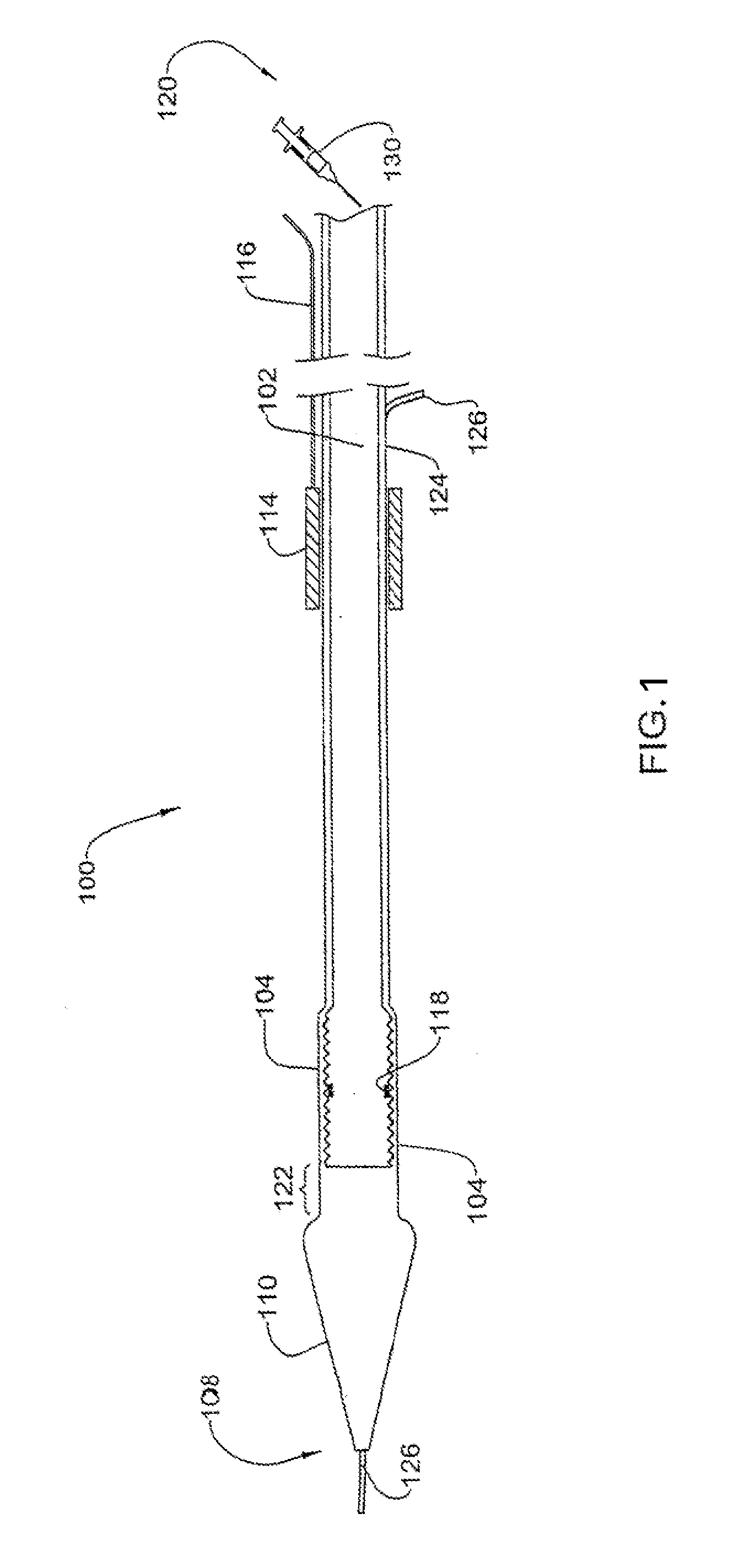
This application is a continuation of U.S. application Ser. No. 14/841,201 filed Aug. 31, 2015, which is a continuation of U.S. application Ser. No. 13/779,327 filed Feb. 27, 2013 (now U.S. Pat. No. 9,119,739), which is a continuation of U.S. application Ser. No. 11/625,237 filed Jan. 19, 2007 (now abandoned), which is a continuation of U.S. application Ser. No. 11/421,653 filed Jun. 1, 2006 (now abandoned), which is a continuation of U.S. application Ser. No. 10/108,985 filed Mar. 29, 2002 (now U.S. Pat. No. 7,147,655), which claims the benefit of foreign priority to IL 142332 filed Mar. 29, 2001, each of which application is hereby incorporated by reference in its entirety. This invention relates to catheters and more specifically to such catheters that are used to implant a stent in an artery. Blood vessels, and particularly arteries, may become stenotic or occluded due to various atherosclerotic processes. A stenotic artery may be treated by balloon angioplasty in which an inflatable balloon mounted on a catheter tip is inserted into the arterial system and navigated through the arterial system to the diseased artery. The balloon is then inflated by means of a pressurized fluid. This causes the balloon to press radially on the arterial wall so as to open the stenosis. A stent may be crimped onto the balloon before insertion so that when the balloon is inflated the stent becomes expanded, The balloon is deflated and withdrawn leaving the expanded stent in the artery. These and other similar methods are well known to the skilled man of the art. It is often necessary to treat several stenoses in a single angioplastic session. For example, it may be necessary to insert a large diameter stent at one location, a small diameter stent at a second location and to perform a balloon angioplasty without a stent at a third location. This could be accomplished by sequential insertion and withdrawal of a catheter, the catheter being loaded each time with the appropriate stent prior to insertion. This however would cause much discomfort to the patient, prolongs the duration of the procedure and increases the chances of damaging a blood vessel. U.S. Pat. No. 6,027,519 discloses a catheter for deploying one or more stents. The stent has one or more individually expandable segments along its length. A stent, in its unexpanded state, is loaded onto each expandable segment of the catheter. The catheter is inserted into the vascular system and positioned with the first expandable segment in a stenosis. An axial force is then applied to the segment causing it to buckle outwards and expand the stent. The force is then removed causing the segment to unbuckle leaving the stent in its expanded state. The catheter is then navigated to another stenosis. This process is repeated until all of the stents have been deployed. The present invention provides a catheter for deploying one or more stents in a cardiovascular system. The catheter is configured to carry one or more stents. Preferably, the catheter carries a plurality of stents. The stents may be of different or the same widths. An inflatable balloon is used to expand a stent surrounding the balloon. The catheter comprises a positioner for moving a stent relative to the balloon from a position in which the stent does not surround the balloon to a position that it does surround the balloon in order to prime the stent for expansion by the balloon. The phrase “for moving a stent relative to the balloon” includes two possibilities, i.e. moving the positioner relative to the balloon and moving the balloon relative to the positioner. In one embodiment of the invention the positioner comprises an element configured to slide along the catheter and push the stents distally along the catheter so as to move a stent adjacent to the balloon into a position in which it surrounds the balloon. The sliding element is pushed along the catheter by means of a wire extending along the catheter from its proximal end to the sliding element. In this embodiment, the stents are deployed in the order in which they are carried by the catheter, starting with the stent closest to the balloon. In another embodiment, the positioner comprises a flexible carriage configured to carry the one or more stents. The carriage is capable of sliding along the catheter in order to bring one of the stents from a position in which the stent does not surround the balloon to a position in which the stent surrounds the balloon. The carriage is moved in either direction along the catheter by means of a wire extending along the catheter from its proximal end to the carriage. It is also possible to position the stent opposite a desired location in the vascular system and slide the balloon through the carriage to a position opposite the stent. In this embodiment the stents may be deployed in the vascular system in any order. It a third embodiment, the catheter comprises two positioners, one posterior positioner as described above in the first embodiment positioned posterior to the balloon, and a second anterior positioner positioned anterior to the balloon. In this embodiment, the anterior positioner may be distanced from the balloon so as to provide a storage space between the anterior positioner and the balloon. The balloon in this embodiment may be a conventional balloon used in balloon angioplasty. In this embodiment also, the stents may be deployed in the vascular system in any order, and may be of different lengths. In use, the catheter is loaded with one or more stents and inserted into a vascular system. The catheter is navigated through the vascular system until the balloon or stent is positioned at a first desired location, typically the site of a stenosis. The stent or balloon is then moved by the positioner so that the stent surrounds the balloon and the balloon is inflated so as to expand the stent. The balloon is then deflated, leaving the expanded stent at the first desired location. This process may be repeated, each time deploying a different stent at a different location. After one or more of the stents have been deployed, the catheter may be removed from the vascular system. The invention also provides a method for deploying a stent in a desired location of a vascular system comprising the steps of: (a) inserting a catheter according to the invention carrying one or more stents into the vascular system, (b) navigating the catheter through the vascular system until the balloon is positioned in the desired location; (c) moving a stent from a first position in which it does not surround the balloon to a second position in which it surrounds the balloon; (d) inflating the balloon so as to expand the stent; and (e) deflating the balloon. In order to understand the invention and to see how it may be carried out in practice, a preferred embodiment will now be described, by way of non-limiting examples only, with reference to the accompanying drawings, in which: A longitudinal shaft 124 in the wall of the tube 102 is configured to receive a guidewire 126 used in navigating the catheter in the vascular system. A neck region 122 of the tube 102 intervenes between the distal end of the balloon 104 and the tip 110. The proximal end of the tip 110 is broadened to form a shoulder at the distal end of the neck region 122. A sliding positioner element in the form of an annular sliding ring 114 is mounted on the tube 102 proximal to the balloon 104. The ring 114 is slidable along the tube 102 by means of a wire 116 that extends along the length of the tube 102 from the proximal end 120 of the catheter to the ring 114. The sliding ring 114 and the wire 116 form a positioner for moving a stent from a position which it does not surround the balloon 104 to a position in which it surrounds the balloon 104. In use, the catheter 100 is introduced into the vascular system and navigated to a stenosis by methods well known in the art. A fluid is then introduced into the tube 102. The fluid passes through the tube 102 and inflates the balloon 104. It will be understood that the balloon may be inflated by other conventional means, as are known in the art. Inflation of the balloon 104 expands the stent 206 The fluid is then withdrawn from the tube 102. Withdrawal of the fluid from the tube 102 causes the balloon to deflate. After deflation of the balloon, the stent 206 The catheter may then be navigated through the arterial system until the catheter is positioned with the balloon 104 at another stenotic region of a blood vessel. The sliding ring is pushed distally by the wire 116 so that the succeeding stent 206 The embodiment of The catheter 600 is introduced into the vascular system and navigated to a stenosis by methods well known in the art. A fluid is then introduced into the tube 102. The fluid passes through the tube 102 and inflates the balloon 104. Inflation of the tube 104 expands the portion of the carriage 605 surrounding the balloon 104 which in turn expands the stent 206 The fluid is then withdrawn from the tube 102 into the syringe 130. Withdrawal of the fluid from the tube 102 causes the balloon to deflate. After deflation of the balloon, the stent 206 The catheter is then navigated through the arterial system until the catheter is positioned with the balloon 104 in another stenotic region of a blood vessel. The catheter is then pushed distally by the wire 116 so that the stent 206 This example illustrates an embodiment which is an improvement over the embodiment described in Example I. With reference to As in Example I, a guidewire 126 extends along the tube 102, exiting at the distal end 108 of the catheter. An anterior positioner in the form of a perforated sphere 706 is fixed to the guidewire anterior to the balloon 704, e.g. the guidewire passes through a bore channel extending through the sphere. The diameter of the sphere is slightly larger than the diameter of the retracted stents which are mounted on the catheter. The purpose of the sphere will be explained below. The catheter 700 has a sliding ring 114 (being the posterior positioner) and a plurality of stents (three are shown in The operation of this embodiment may be understood with reference to Thus, this embodiment also differs from that of Example I in having more room to store the separating rings. In addition, all of the mounted stents and rings may be moved distally and proximally by pulling and pushing the anterior and posterior positioners, being the sphere 706 and sliding ring 114, respectively, so that the stents may be deployed in any order. This differs from Example I where the stents were required to be deployed in the order in which they were placed on the catheter. A catheter configured to carry one or more stents and having an inflatable balloon for expanding a stent surrounding the balloon. The catheter is characterized in having a positioner for moving the one or more stents relative to the balloon from a first position in which the stent does not surround the balloon to a second position in which the stent surrounds the balloon. Also disclosed is a method for deploying a stent at a desired location in the vascular system. 1. A stent delivery system, comprising:
a catheter having a distal end; an inflatable balloon near the distal end for expanding a stent surrounding the balloon; a plurality of stents carried upon the catheter; a separating mechanism carried upon the catheter, wherein a stent to be expanded is separated from an undeployed adjacent stent via the separating mechanism; and a positioner which is longitudinally slidable along the catheter independently of the plurality of stents such that the positioner is configured to move the plurality of stents relative to the balloon from a first position to a second position in proximity to the distal end so that at least one of the plurality of stents surrounds the balloon. 2. The system of 3. The system of 4. The system of 5. The system of 6. A stent delivery system, comprising:
a catheter having a distal end; an inflatable balloon near the distal end for expanding a stent surrounding the balloon; a plurality of stents carried upon the catheter; a separating mechanism carried upon the catheter, wherein a stent to be expanded is separated from an undeployed adjacent stent via the separating mechanism; and a positioner which is longitudinally slidable along the catheter and adapted to engage a proximal stent of the plurality of stents to move the plurality of stents relative to the balloon from a first position to a second position in proximity to the distal end so that at least one of the plurality of stents surrounds the balloon for deployment therefrom. 7. The system of 8. The system of 9. The system of 10. The system of 11. The system of 12. The system of 13. The system of RELATED APPLICATION DATA
FIELD OF THE INVENTION
BACKGROUND OF THE INVENTION
SUMMARY OF THE INVENTION
BRIEF DESCRIPTION OF THE DRAWINGS
DETAILED DESCRIPTION OF THE INVENTION
EXAMPLE I
EXAMPLE II
EXAMPLE III