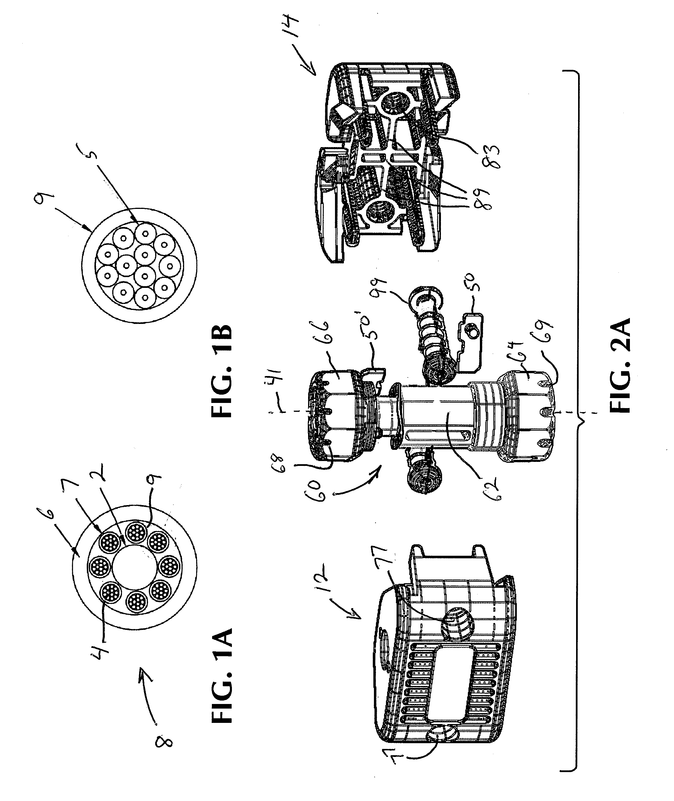
FIBER OPTIC CABLE BUFFER TUBE MID-SPAN ACCESS TOOL
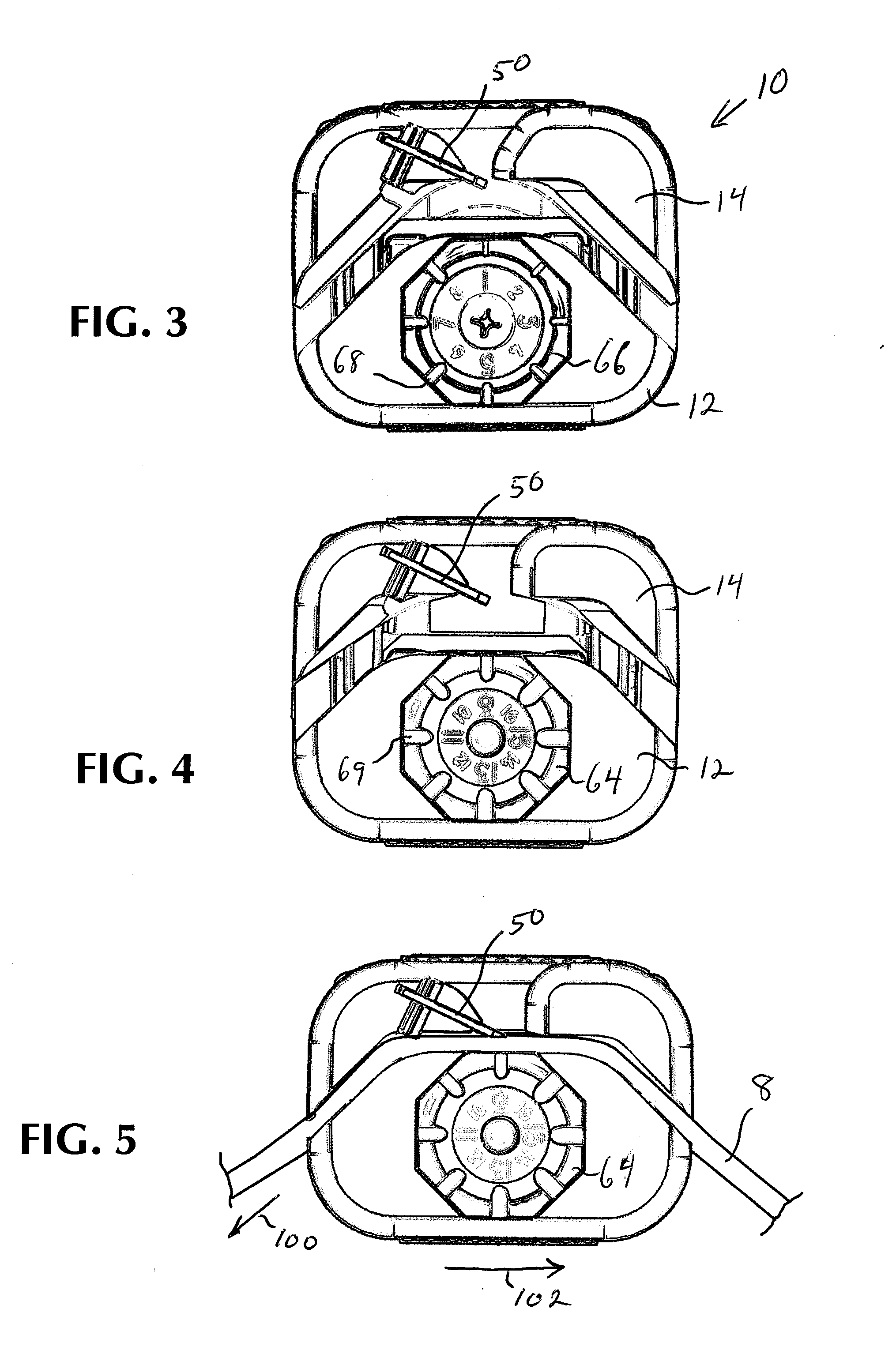
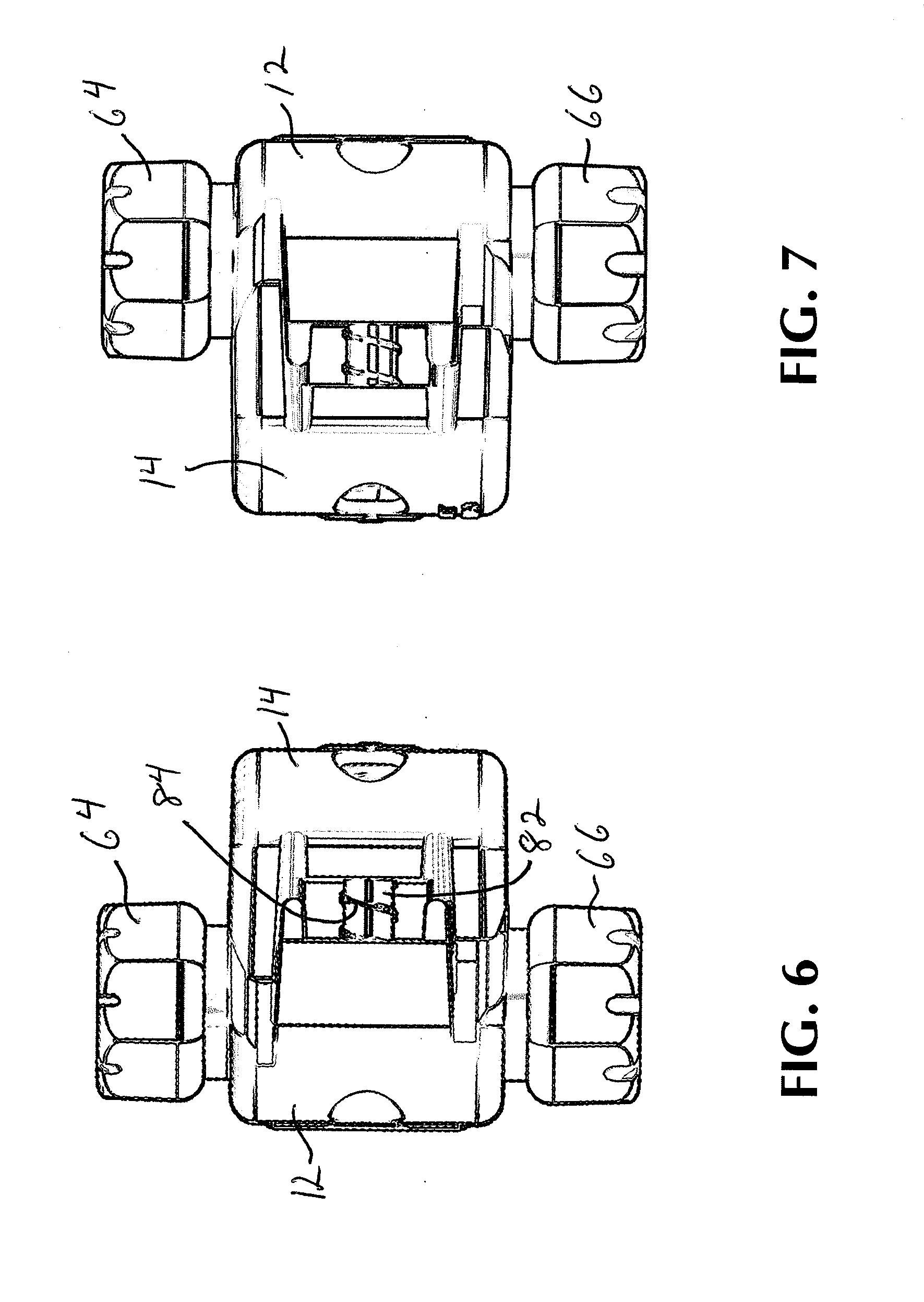
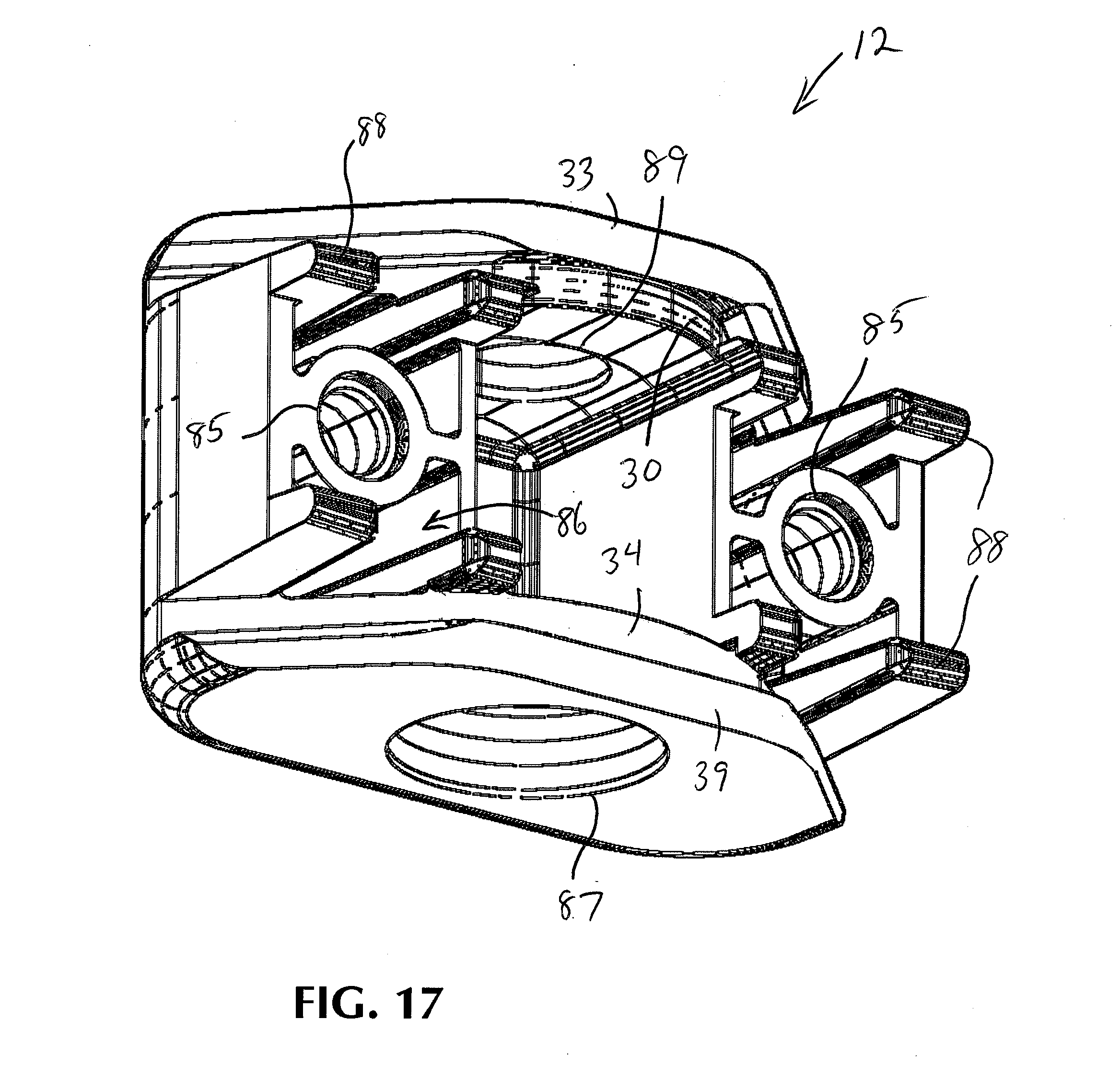
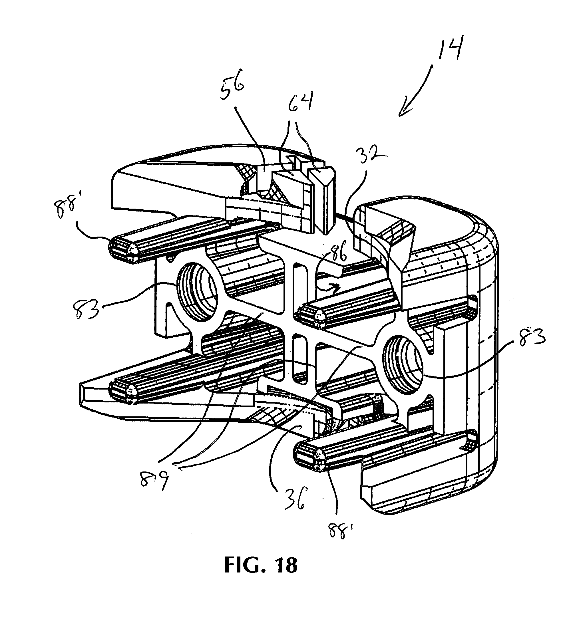
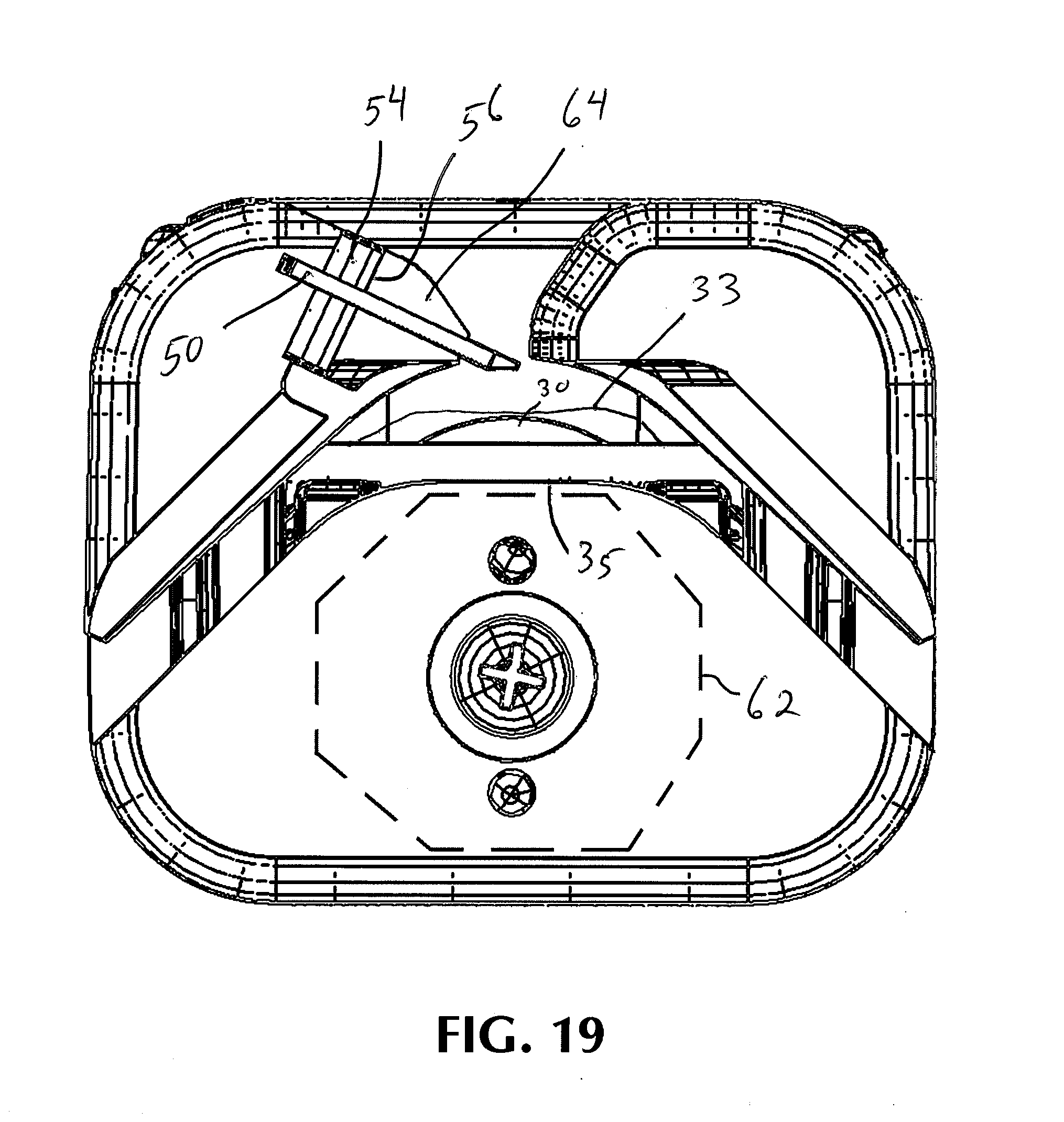
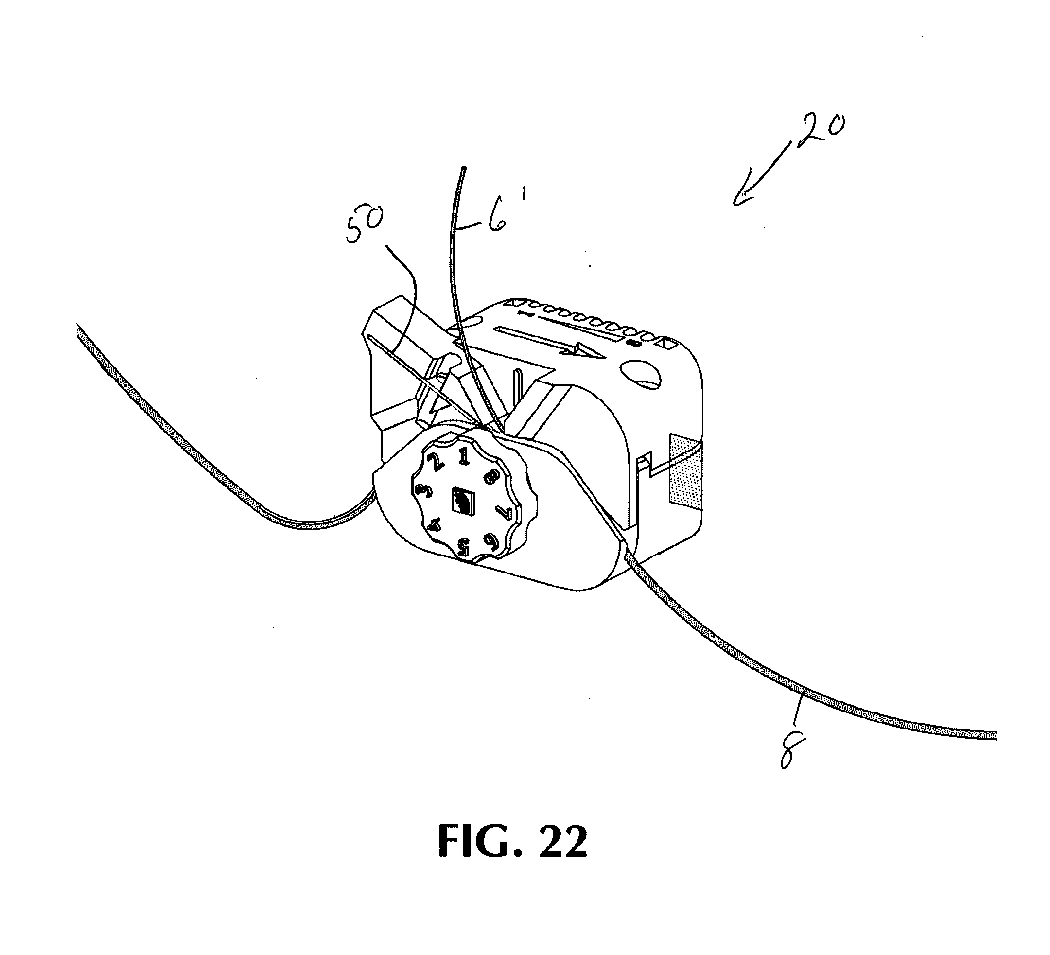
The present invention is directed to a tool for removing insulation in mid-span of a cable carrying a plurality of optical fibers or other signal-transmitting conduits. Fiber optic cables are becoming more popular because the distance a signal can travel within a single fiber is far greater than in traditional copper cables. Installing these cables is time consuming because cable preparation is vital to signal strength. The fiber optic cables are very fragile, and any damage could dramatically reduce the performance of the cable. As with any cable network, the need to perform mid-span access is necessary. Mid-span cable preparation is more difficult because you cannot simply slip the cable construction off the end of the cable. Midspan access is common since service loops are used for long cable runs to allow for future expansion and configuration. Typical fiber optic cable 8 construction such as the one shown in One of the final steps for accessing mid-spanning fiber optics is removing a portion of insulation of the buffer tube around the fiber optic cables to exposed the individual signal-carrying fiber strands. Different cable manufacturers use different diameter buffer tubes, causing an installer to purchase and use a different tool for each tube size. Loose buffer tubes are typically 0.004-0.010″ thick depending on tube diameter and manufacturer. Improper tool sizing can cause fiber damage or cause the tool to not strip the tube from the fiber. These buffer tube sizes range from 1.0 mm to 3.0 mm and a certain tool can only be used over a small range (0.1 mm-0.2 mm) because of the precision involved. Current tools are highly specialized and sized specifically for the buffer tube. They have a split housing design with scoring blades on each side that penetrate the wall of the buffer tube with a side hinge to allow the tool to be placed over the tube section. These tools are specifically sized with blade depths and inside diameter. Loading a smaller or larger tube could cause damage to the fibers within the tube. Some tools combine multiple channels into one tool. This saves the end user from using multiple tools for different cables. However, this tool also causes loading errors from using the wrong channel and fiber damage from clamping the tool when the buffer tubes has spanned multiple channels. Other tool designs use shaving as the means of exposing a window in the buffer tube. The resulting buffer tube window exposes the individual fiber strands, but it is critical that the act of opening the buffer tube window does not nick or contact the individual fiber strands. However, the current platforms do not have the accuracy to shave the buffer tube for smaller sized cables (˜less than 2 mm). Other, more expensive tools use shaving to remove the buffer tube, however they are very complicated. The precision is a result of accurately machined inserts that are used for each individual buffer tube size. The tool body itself is very expensive and for each buffer tube size a precision insert must be purchased. This is not an economical or versatile solution: It would be useful to have an improved means to remove fiber optic strands from buffer tube. Bearing in mind the problems and deficiencies of the prior art, it is therefore an object of the present invention to provide a tool and for removing insulation in mid-span of a cable carrying a plurality of signal-transmitting conduits which utilizes an improved fiber alignment channel, fine adjustment mechanism, and range multiplying feature to maximize precision and range of the tool. It is another object of the present invention to provide a tool and for removing insulation in mid-span of a cable carrying a plurality of signal-transmitting conduits which allows for all buffer tubes to be accurately shaved all with one tool. It is still another object of the present invention to provide a tool having a fine adjustment barrel for accurate setting adjustment. It is another object of the present invention to provide a tool having a cable alignment arc which orients fibers inside buffer tube and creates accurate and repeatable presentation of fiber to blade and preload area It is a further object of the present invention to provide an access tool which is easily manufactured from a polymer. It is yet another object of the present invention to provide a range multiplying feature to effectively double the range of the tool. It is still a further object of the present invention to provide an access tool having a blade which is easily replaced and is secured by blade supports which limit the flex of the blade. It is another object of the present invention to provide a tool including cable sizing gaps for field evaluation of tool settings. Still other objects and advantages of the invention will in part be obvious and will in part be apparent from the specification. The above and other objects, which will be apparent to those skilled in the art, are achieved in the present invention which is directed a tool for removing insulation in mid-span of a cable carrying a signal-transmitting conduit comprising a lower body section and an upper body section movable toward and away from the lower body section. The tool includes a curved mandrel disposed on the lower body section, the curved mandrel having a central peak portion and adjacent portions curving downward away from the peak portion, to present a mid-span portion of the cable insulation on a side away from the mandrel peak portion. The tool includes a blade disposed on the upper body section, the blade movable toward and away from the curved mandrel. The cable is securable in the curved mandrel in a curved position, allowing the blade to shave the cable insulation allowing access to the signal-transmitting conduit. The tool may include an adjustment barrel having a length and a central axis extending the length of the barrel and including a plurality of height adjustment surfaces each adjustment surface disposed at a different distance from the barrel axis wherein each height adjustment surface positions the blade a different distance from the mandrel. The tool may include an adjustment knob for controlling the distance between the upper body section and the lower body section when the tool is in a closed position. The adjustment knob may include a knob face and a plurality of sizing notches disposed in the knob face, each sizing notch corresponding with the diameter of different diameter cables. The tool may include a cable channel disposed along the curved surface of the mandrel, the cable slidable along the cable channel when the cable is disposed in the cable channel and including a cable guide disposed on the upper body portion wherein the cable guide secures the cable in the cable channel when the upper body portion is in a position toward the lower body portion wherein the blade extends through the cable guide to contact the portion of the cable insulation at the mandrel peak. The mandrel may be a first mandrel disposed on one side of the lower body portion and the tool may include a second mandrel on the opposite side of the lower body portion than the first mandrel. The cable guide may be a first cable guide disposed on the upper body portion adjacent the first mandrel and the tool may include a second cable guide adjacent the second mandrel wherein the first cable guide secures a first cable in the first cable channel when the upper body portion is in a position toward the lower body portion or the second cable guide secures a second cable having a different diameter'than the first cable diameter when the upper body portion is in a position toward the lower body portion. The blade may be a first blade disposed on the upper body portion adjacent the first mandrel and the tool may include a second blade adjacent the second mandrel. The tool may include an adjustment barrel having a length and a central axis extending the length of the barrel and may include a plurality of height adjustment surfaces each adjustment surface disposed at a different distance from the barrel axis. The tool may include a first adjustment knob on one end of the barrel corresponding with one range of cable diameters and a second adjustment knob on the opposite end of the barrel corresponding with a second range of cable diameters. Each of the adjustment knobs may include a knob face and a plurality of sizing notches disposed in the knob face, each sizing notch corresponding with the diameter of different diameter cables. The lower body portion may include at least one alignment member and the upper body portion may include at least one alignment opening slidingly engageable with the at least one alignment member wherein the upper body portion maintains a position parallel with the lower body portion when the upper body portion is moved toward or away from the lower body section. The tool may include a stop fastener disposed on the at least one alignment member wherein the upper body portion is limited in the distance the upper body portion is movable in a direction away from the lower body portion. The tool may include a compression spring disposed on the at least one alignment member wherein the upper body portion is biased away from the lower body portion. The tool may include a loading member contacting the cable insulation on the side of the cable away from the mandrel, in a location adjacent to and prior to the cable insulation being shaved by the blade. The tool may include blade supports contacting both sides of the blade over a substantial portion of the surface thereof. The tool may include a loading member contacting the cable insulation on the side of the cable away from the mandrel, in a location adjacent to and prior to the cable insulation being shaved by the blade, and blade supports contacting both sides of the blade over a substantial portion of the surface thereof, the tool housing being adjustably secured to the curved mandrel to adjust the distance therebetween. The plane of the blade may be at an acute angle to the longitudinal axis of the cable at the mandrel central peak portion, and the blade may have a cutting edge oriented perpendicular to the cable longitudinal axis and cut a desired circumferential width of the insulation. The cable insulation on the side of the cable away from the mandrel peak portion may be in tension before being contacted by the blade. The barrel and control surfaces may be planar, and the different adjacent barrel surfaces around the barrel circumference set to increasingly greater or smaller distances from the central axis. The tool may include a knob for rotating the barrel, the knob having indicia thereon to indicate the selected one of the barrel surfaces presented toward the control surface. Another aspect of the present invention is directed to a tool for cutting or removing insulation from a cable carrying a plurality of signal-transmitting conduits. The tool comprises a housing having a first housing portion for supporting the cable and a second housing portion for securing a blade to cut or remove insulation from the cable supported by the first housing portion, the first and second housing portions being moveable toward and away from each other to position the blade a desired distance from the cable supported by the first housing portion. The tool includes a barrel rotatable about a central axis and having plurality of surfaces around its circumference, each of the barrel surfaces being located at a different distance from the central axis and a control surface for contacting one of the barrel surfaces. The control surface is disposed on one of the first or second housing portions and the barrel is rotatably secured to the other of the first or second housing portions to present a selected one of the barrel surfaces to the control surface. When the first and second housing portions are moved toward each other, the selected barrel surface contacts the control surface and establishes the closest distance between the housing portions and the distance of the blade from the cable supported by the first housing portion. When the distance between the first and second housing portions is established by contact between the selected one of the barrel surfaces and the control surface, the established distance is fixed and the cable is moved relative to the housing to use the blade to cut or remove the insulation from the cable. Another aspect of the present invention is directed to a method for shaving insulation from a cable carrying at least one signal-transmitting conduits. The method includes providing a cable having cable insulation around a plurality of signal-transmitting conduits and providing the tool for removing insulation comprising a lower body section and an upper body section movable toward and away from the lower body section, a curved mandrel disposed on the lower body section, the curved mandrel having a central peak portion and adjacent portions curving downward away from the peak portion, to present a mid-span portion of the cable insulation on a side away from the mandrel peak portion and a blade disposed on the upper body section, the blade movable toward and away from the curved mandrel. The method includes ensuring the tool is in an open position and securing the cable in the curved mandrel in a curved position. The method includes moving the first and second housing portions toward each other, fixing the established distance between the housing portions and the distance of the blade from the cable supported by the first housing portion. The method includes moving the cable relative to the housing and using the blade to cut or remove the insulation from the cable. The method includes moving the first and second housing portions away from each other and removing the cable from the curved mandrel. The tool may include an adjustment barrel having a length and a central axis extending the length of the barrel and including a plurality of height adjustment surfaces each adjustment surface disposed at a different distance from the barrel axis wherein each height adjustment surface positions the blade a different distance from the mandrel and the method includes rotating the barrel to present a selected barrel surface toward the control surface, and the step of moving the first and second housing portions toward each other includes moving the first and second housing portions until the selected barrel surface contacts the control surface, fixing the established distance between the housing portions and the distance of the blade from the cable supported by the first housing portion. The features of the invention believed to be novel and the elements characteristic of the invention are set forth with particularity in the appended claims. The figures are for illustration purposes only and are not drawn to scale. The invention itself, however, both as to organization and method of operation, may best be understood by reference to the detailed description which follows taken in conjunction with the accompanying drawings which describe and show a preferred embodiment of the present invention in various side, top, bottom and perspective views. In describing the embodiment(s) of the present invention, reference will be made herein to the drawings below and The present invention provides precise tool and method of use to shave an access window into a range of sizes of buffer tubes for signal-transmitting conduits, primarily fiber optic cables. The tool may also be used for shaving insulation from other cables or tubes carrying the signal-transmitting conduits such as electrical wires. In a first embodiment of the shaving tool 10 shown in An adjustment barrel 60 shown in The lower body portion 12 includes at least one alignment member 82 and the upper body portion includes at least one alignment opening 83 slidingly engageable with the at least one alignment member 82 wherein the upper body portion 14 maintains a position parallel with the lower body portion 12 when the upper body portion 14 is moved toward or away from the lower body section 12. A stop fastener. 99 is disposed on the at least one alignment member 82 wherein the upper body portion 14 is limited in the distance the upper body portion 14 is movable in a direction away from the lower body portion 12 and including a compression spring 84 disposed on the at least one alignment member 82 biasing the upper body portion 14 away from the lower body portion 12. In a method of using mid-span access tool 10 shown in In a second embodiment of the tool 20 shown in The tool may include a loading member 60 contacting the cable insulation 6 on the side of the cable 8 away from the mandrel 40, in a location adjacent to and prior to the cable insulation being shaved by the blade 50. The tool 20 may include blade supports 64 contacting both sides of the blade 50 over a substantial portion of the surface thereof. The tool 20 may include a tool housing 22 Tool upper half 22 Each tool half also includes cable channel 40. The channel includes geometric features that allow the tool 20 to shave or strip insulation on the large range of tube sizes. As the tool 20 is closed to its desired setting, the partial cable channel sections 40 Each setting of knob 76 moves the blade 50, preload area 60 and constraint surfaces 40 The blade 50 may be positioned in the top tool half 22 The buffer tube 8 is loaded onto the curved mandrel 40 in the tool bottom half 22 The blade 50 depth settings are achieved by closing the two halves of the tool. The gap between the tool halves are set by the adjusting barrel 70, which is housed in the tool bottom half 22 The range multiplying device 90 is a spacer or shim that may double or otherwise increase the effective cable diameter range of the tool. It provides a variable control surface 90 slideable on track 94 in and out between the barrel 70 and base control surface 80 in top half 22 The tool 20 also has sizing gaps 96 of different widths that operate as gauges to allow the end user to understand which barrel position should be used. In the field, it is not practical that the end user will know what diameter they are working with and the sizing gauge will help the end user quickly establish the tool setting. The tool as described above provides for removing insulation in mid-span of a cable carrying a plurality of signal-transmitting conduits which utilizes an improved fiber alignment channel, fine adjustment mechanism, and range multiplying feature to maximize precision and range of the tool. The tool provides for removing insulation in mid-span of a cable carrying a plurality of signal-transmitting conduits which allows for all buffer tubes to be accurately shaved all with one tool. The tool also provides a fine adjustment barrel for accurate setting adjustment and an alignment arc which orients fibers inside buffer tube and creates accurate and repeatable presentation of fiber to blade and preload area. The tool is easily manufactured from a polymer and provides a range multiplying feature to effectively double the range of the tool. The tool provides a blade which is easily replaced and is secured by blade supports which limit the flex of the blade. The tool provides cable sizing gaps for field evaluation of tool settings. While the present invention has been particularly described, in conjunction with a specific preferred embodiment, it is evident that many alternatives, modifications and variations will be apparent to those skilled in the art in light of the foregoing description. It is therefore contemplated that the appended claims will embrace any such alternatives, modifications and variations as falling within the true scope and spirit of the present invention. A tool for removing insulation in mid-span of a cable carrying a signal-transmitting conduit comprising a lower body section and an upper body section movable toward and away from the lower body section. The tool includes a curved mandrel disposed on the lower body section, the curved mandrel having a central peak portion and adjacent portions curving downward away from the peak portion, to present a mid-span portion of the cable insulation on a side away from the mandrel peak portion. The tool includes a blade disposed on the upper body section, the blade movable toward and away from the curved mandrel. The cable is securable in the curved mandrel in a curved position, allowing the blade to shave the cable insulation allowing access to the signal-transmitting conduit. The tool may include an adjustment barrel having a plurality of height adjustment surfaces disposed at a different distance from the barrel axis, each height adjustment surface positioning the blade a different distance from the mandrel. 1. A tool for removing insulation in mid-span of a cable carrying a signal-transmitting conduit comprising:
a lower body section and an upper body section movable toward and away from the lower body section; a curved mandrel disposed on the lower body section, the curved mandrel having a central peak portion and adjacent portions curving downward away from the peak portion, to present a mid-span portion of the cable insulation on a side away from the mandrel peak portion; a blade disposed on the upper body section, the blade movable toward and away from the curved mandrel; wherein the cable is securable in the curved mandrel in a curved position, allowing the blade to shave the cable insulation allowing access to the signal-transmitting conduit. 2. The tool of 3. The tool of 4. The tool according to 5. The tool of 6. The tool of 7. The tool of 8. The tool according to 9. The tool of 10. The tool of 11. The tool of 12. The tool of 13. The tool of 14. The tool of 15. The tool of 16. The tool of 17. The tool of 18. A tool for cutting or removing insulation from a cable carrying a plurality of signal-transmitting conduits comprising:
a housing having a first housing portion for supporting the cable and a second housing portion for securing a blade to cut or remove insulation from the cable supported by the first housing portion, the first and second housing portions being moveable toward and away from each other to position the blade a desired distance from the cable supported by the first housing portion; a barrel rotatable about a central axis and having plurality of surfaces around its circumference, each of the barrel surfaces being located at a different distance from the central axis; a control surface for contacting one of the barrel surfaces, wherein the control surface is disposed on one of the first or second housing portions and the barrel is rotatably secured to the other of the first or second housing portions to present a selected one of the barrel surfaces to the control surface, wherein when the first and second housing portions are moved toward each other, the selected barrel surface contacts the control surface and establishes the closest distance between the housing portions and the distance of the blade from the cable supported by the first housing portion, and wherein when the distance between the first and second housing portions is established by contact between the selected one of the barrel surfaces and the control surface, the established distance is fixed and the cable is moved relative to the housing to use the blade to cut or remove the insulation from the cable. 19. A method for shaving insulation from a cable carrying at least one signal-transmitting conduits comprising:
providing a cable having cable insulation around a plurality of signal-transmitting conduits; providing a tool for removing insulation comprising a lower body section and an upper body section movable toward and away from the lower body section, a curved mandrel disposed on the lower body section, the curved mandrel having a central peak portion and adjacent portions curving downward away from the peak portion, to present a mid-span portion of the cable insulation on a side away from the mandrel peak portion; and a blade disposed on the upper body section, the blade movable toward and away from the curved mandrel; ensuring the tool is in an open position; securing the cable in the curved mandrel in a curved position; moving the first and second housing portions toward each other, fixing the established distance between the housing portions and the distance of the blade from the cable supported by the first housing portion; moving the cable relative to the housing and using the blade to cut or remove the insulation from the cable; moving the first and second housing portions away from each other; and removing the cable from the curved mandrel. 20. The method of clam 19 wherein the tool includes an adjustment barrel having a length and a central axis extending the length of the barrel and including a plurality of height adjustment surfaces each adjustment surface disposed at a different distance from the barrel axis wherein each height adjustment surface positions the blade a different distance from the mandrel and the method includes rotating the barrel to present a selected barrel surface toward the control surface, and the step of moving the first and second housing portions toward each other includes moving the first and second housing portions until the selected barrel surface contacts the control surface, fixing the established distance between the housing portions and the distance of the blade from the cable supported by the first housing portion.BACKGROUND OF THE INVENTION
1. Field of the Invention
2. Description of Related Art
SUMMARY OF THE INVENTION
BRIEF DESCRIPTION OF THE DRAWINGS
DESCRIPTION OF THE EMBODIMENT(S)