CENTRIFUGAL COMPRESSOR
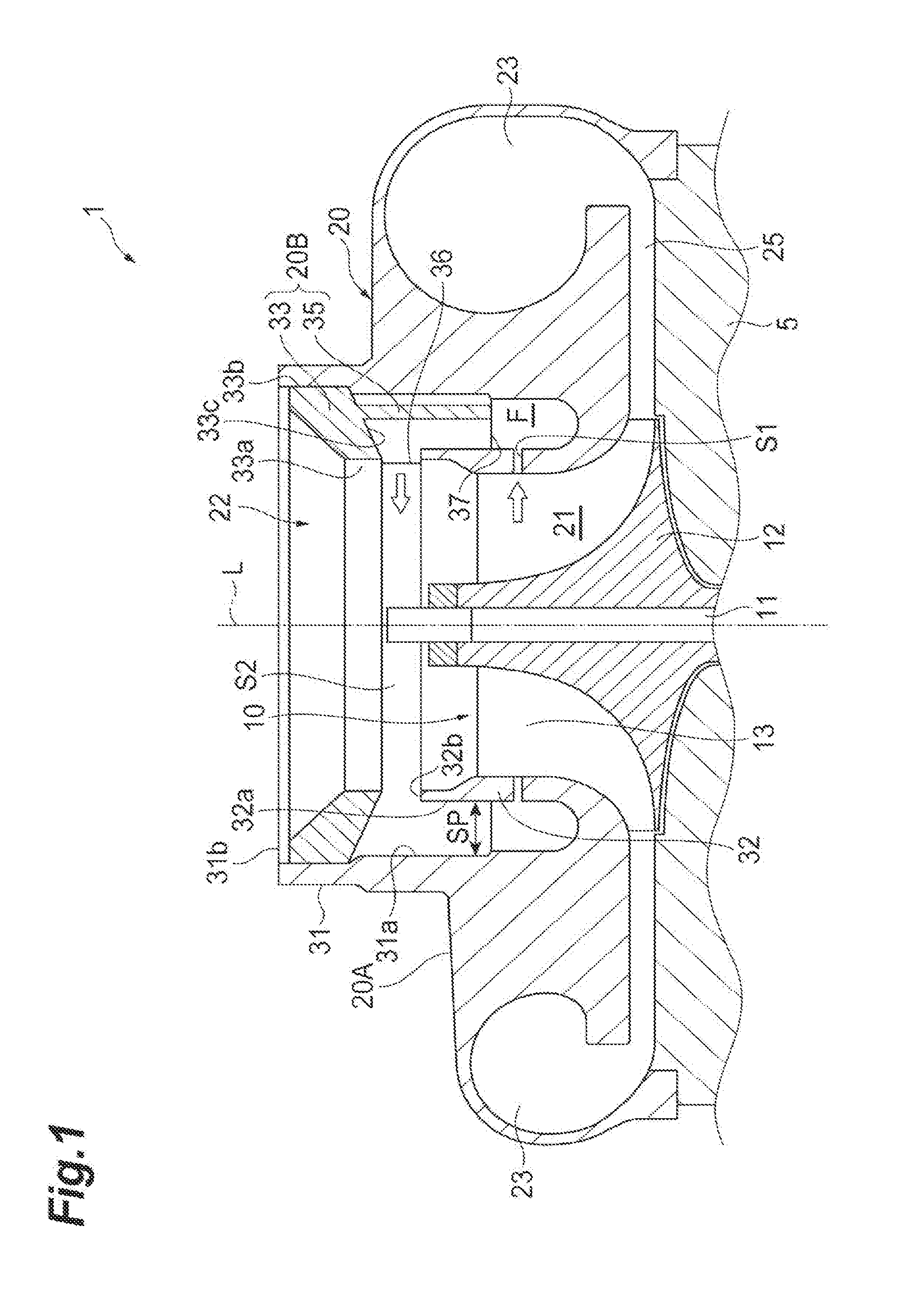
The present disclosure relates to a centrifugal compressor. in related art, a centrifugal compressor that suppresses occurrence of surging during low flow rate operation has been known. For example, the centrifugal compressor disclosed in Patent Literature 1 includes an annular treatment cavity portion (circulation flow path) in a shroud wall forming an intake port. A plurality of baffle plates is disposed at equal intervals in the treatment cavity portion. Patent Literature 1: Japanese Unexamined Patent Publication No. 2001-289197 Generally, at an impeller outlet side of the centrifugal compressor, a non-uniform static pressure distribution in a circumferential direction is formed due to the non-axisymmetric nature of a scroll at a non-design point. In a case where the non-uniform static pressure distribution is formed, there is a risk of a difficulty in expansion of an operation range toward the low flow rate side due to the occurrence of surging. In a case where a circulation path is formed as in the centrifugal compressor disclosed in Patent Literature 1, since the flow rate to the impeller is increased by the fluid passing through the circulation path, and the operation of the centrifugal compressor is stabilized, occurrence of surging is suppressed. However, since such a centrifugal compressor is also affected by the non-uniform static pressure distribution on the impeller outlet side, there is a risk of a difficulty in expansion of the operation range toward the low flow rate side. The present disclosure describes a centrifugal compressor capable of expanding the operation range to the low flow rate side. A centrifugal compressor of an aspect is equipped with a housing including a suction passage which accommodates an impeller. The suction passage is provided with a first opening portion formed at a position facing the impeller, a second opening portion formed on an upstream side of the first opening portion, a circulation flow path which allows the first opening portion and the second opening portion to communicate with each other and extends in an annular shape around a rotational axis of the impeller, and a plurality of guide vanes disposed in the circulation flow path. The circulation flow path includes a first region in which a plurality of guide vanes is disposed at intervals in a circumferential direction, and a second region in which no guide vane is disposed, and the second region extends over a wider range in the circumferential direction than the interval between the guide vanes in the first region. According to the centrifugal compressor according to the present disclosure, it is possible to expand the operation range to the low flow rate side. A centrifugal compressor of an aspect includes a housing including a suction passage which accommodates an impeller, and the suction passage is provided with a first opening portion formed at a position facing the impeller, a second opening portion formed on an upstream side of the first opening portion, a circulation flow path which allows the first opening portion and the second opening portion to communicate with each other and extends in an annular shape around a rotational axis of the impeller, and a plurality of guide vanes disposed in the circulation flow path. The circulation flow path includes a first region in which a plurality of guide vanes is disposed at intervals in a circumferential direction, and a second region in which the guide vane is not disposed, and the second region extends over a wider range in the circumferential direction than the interval between the guide vanes in the first region. According to this centrifugal compressor, the fluid flowing into the circulation path from the first opening portion flows out of the second opening portion toward the impeller. Since a first region and a second region are formed in the circulation path, the guide vanes in the circulation path are unevenly distributed in the circumferential direction. As a result, the fluid flowing out of the second opening portion is in a non-uniform state in the circumferential direction. Therefore, since the inflow condition into the impeller changes in the circumferential direction, the static pressure distribution on the impeller outlet side can be improved. Therefore, it is possible to expand the operation range to the low flow rate side. Further, the housing may include an annular scroll flow path formed on an outer circumference of the impeller, and a discharge path communicating with the scroll flow path, and the first region may be formed in an angular range of ±90° on the basis of a connecting portion between the scroll flow path and the discharge path around the rotational axis of the impeller. Further, the connecting portion between the scroll flow path and the discharge path may be included in the angular range in which the first region is formed when centered on the rotational axis. According to such a configuration, since the first region is formed on the side of the connecting portion between the scroll flow path and the discharge port, the static pressure distribution of the impeller outlet on the connecting portion side is made uniform in the circumferential direction. Further, the guide vane formed in the first region may be inclined in a direction in which the fluid is discharged in a direction opposite to a rotational direction of the impeller. In this configuration, at a position where the first region is formed, the fluid flowing out of the second opening flows in a direction opposite to the rotational direction of the impeller. Therefore, it is possible to raise the lift (head, loading) of the impeller at that position. Also, the housing may include an insert ring which is mounted on the suction passage and fauns a second opening portion, and the insert ring may include a guide vane. According to this configuration, it is possible to easily manufacture a circulation path provided with the guide vanes. Further a centrifugal compressor according to an aspect includes a housing including a suction passage which accommodates an impeller. The suction passage is provided with a first opening portion formed at a position facing the impeller, a second opening portion formed on an upstream side of the first opening portion, a circulation flow path which allows the first opening portion and the second opening portion to communicate with each other and extends in an annular shape around a rotational axis of the impeller, and a plurality of guide vanes disposed in the circulation flow path to be spaced apart from each other in the circumferential direction. The plurality of guide vanes is formed in a non-axisymmetric manner about the rotational axis of the impeller so that the fluid flowing out of the second opening portion is in a non-uniform state in the circumferential direction, and plurality of guide vanes makes a static pressure distribution at the outlet side of the impeller uniform. According to this centrifugal compressor, the fluid flowing into the circulation path from the first opening portion flows out of the second opening portion toward the impeller. In the circulation path, a plurality of guide vanes is disposed so as to be non-axisymmetric about the rotational axis of the impeller. Accordingly, the fluid flowing out of the second opening portion is in a non-uniform state in the circumferential direction. Therefore, since the inflow condition into the impeller changes in the circumferential direction, the static pressure distribution on the impeller outlet side can be improved. Therefore, it is possible to expand the operation range to the low flow rate side. Hereinafter, embodiments of the present disclosure will be specifically described with reference to the drawings. For the sake of convenience, in some cases, substantially the same elements are denoted by the same reference numerals, and the description thereof will not be provided. In the following description, in the case of “upstream” or “downstream”, a flow direction of a main stream traveling from a suction passage to a scroll flow path rather than a flow direction of the circulation flow flowing through the circulation flow path is used as a reference. The housing 20 includes a housing body 20A and an insert ring 20B. The housing body 20A includes an annular scroll flow path 23 and a discharge portion (discharge path) 24 (see An end portion 32 The insert ring 20B forms a part of a casing treatment structure. The guide vane 35 has a plate shape and is erected on the bottom surface 33 The base portion 33 side of the guide vane 35 extends from the end edge on the inner side surface 33 The arrangement of the plurality of guide vanes 35 will be described with reference to A tongue portion 28 is provided in a connecting portion 27 between the scroll flow path 23 and the discharge portion 24. The scroll flow path 23 in the scroll flow path 26 extends from a scroll start portion 23 In the present embodiment, a plurality of guide vanes 35 is disposed at intervals in the circumferential direction. These guide vanes 35 are disposed in a partial range of the base portion 33 in the circumferential direction. Accordingly, the circulation flow path F includes a first region R1 in which the plurality of guide vanes 35 is disposed in the circumferential direction, and the second region R2 in which the guide vane 35 is not disposed. The second region R2 extends over a wider range in the circumferential direction than the interval between the guide vanes 35 in the first region R1. In the present embodiment, the first region R1 in which the guide vanes 35 are formed is a region having a central angle of about 90° around the rotational axis L in the annular circulation flow path F. In the first region R1, the plurality of guide vanes 35 is disposed at equal intervals with, for example, a pitch angle θ of about 20° to 30°. In the illustrated example, the pitch angle θ of the guide vanes 35 is about 22.5°. On the other hand, the second region R2 is a region in which the guide vane 35 is not formed, and is a region having a central angle of about 270° around the rotational axis L in the annular circulation flow path F. Further, in the present embodiment, the first region RI is formed in an angular range of ±90° on the basis of the connecting portion 27 (tongue portion 28) between the scroll flow path 23 and the discharge portion 24 around the rotational axis L. In the example illustrated in Next, the operation and effect of the centrifugal compressor 1 in the present embodiment will be described. In this way, according to the centrifugal compressor 1 of the present embodiment, the air flowing into the circulation flow path F from the slit S1 flows out of the slit toward the impeller 10. Since the first region R1 and the second region R2 are formed in the circulation flow path F, the guide vanes 35 in the circulation flow path F arc unevenly distributed in the circumferential direction. As a result, the fluid flowing out of the slit S2 is in a non-uniform state in the circumferential direction. Therefore, since the inflow condition to the impeller 10 changes in the circumferential direction, it is possible to improve the static pressure distribution in the diffuser 25 which is the outlet side of the impeller 10. Therefore, it is possible to expand the operation range to the low flow rate side. Further, the first region R1 is formed in an angular range of ±90° on the basis of the tongue portion 28 which is the connecting portion 27 between the scroll flow path 23 and the discharge portion 24 around the rotational axis L of the impeller 10. In particular, the tongue portion 28 is included in the angular range in which the first region R1 is formed when centered on the rotational axis L. Since the first region R1 is formed on the tongue portion 28 side in this way, it is possible to improve the uniformity of the static pressure distribution of the impeller outlet on the tongue portion 28 side in which the static pressure ratio tends to decrease. Further, the guide vane 35 formed in the first region R1 is inclined in a direction in which the fluid is discharged in a direction opposite to the rotational direction of the impeller 10. In this configuration, at the position where the first region R1 is formed, the air flowing out of the slit S2 flows in a direction opposite to the rotational direction of the impeller 10. Therefore, it is possible to raise lift (head, loading) of the impeller 10 at this position. Therefore, the work of the impeller 10 rises as compared with the position where the second region R2 is formed, and it is possible to improve the static pressure distribution on the outlet side of the impeller 10. Further, the housing 20 includes an insert ring 20B which is mounted in the suction passage 22 and forms the slit S2. A guide vane 35 is provided in the insert ring 20B. According to such a configuration, it is possible to easily manufacture the circulation flow path F including the guide vane 35. Although the embodiment of the present disclosure has been described in detail with reference to the drawings, the specific configuration is not limited to this embodiment. For example, In this embodiment, as an example in which the guide vanes 35 are disposed to be inclined with respect to the radial direction, an example is illustrated in which the guide vanes 35 are inclined in a direction in which the air is discharged in the direction opposite to the rotational direction of the impeller 10. However, the embodiment is not limited thereto. For example, as illustrated in Further, in the embodiment, an example in which the center of the first region R1 in the circumferential direction around the rotational axis L substantially coincides with the position of the tongue portion 28 is illustrated, but the present invention is not limited thereto. The first region R1 may be formed at any position in the circumferential direction. For example, as illustrated in Further, in the embodiment, the example in which the second region R2 is formed only partly is illustrated, but the present invention is not limited thereto. For example, as illustrated in Further, in the embodiment, the example in which the first region R1 is formed only partially is illustrated, but the present invention is not limited thereto. A plurality of the first regions R1 may be formed. For example, as illustrated in Further, in the embodiment, the example in which the air flowing out of the slit S2 is made non-uniform in the circumferential direction by forming the first region R1 and the second region R2 is illustrated, but the present invention is not limited thereto. That is, a plurality of guide vanes may be formed all over the circumferential direction. The guide vanes are formed in a non-axisymmetric manner around the rotational axis 11 of the impeller 10 so that the air flowing out of the slit S2 is in a non-uniform state in the circumferential direction. As a result, the static pressure distribution on the outlet side of the impeller 10 is made uniform. An example of such a form will be described with reference to For example, in the example illustrated in Also, as illustrated in Further, as illustrated in In Further, as illustrated in In the above-described embodiment and modified example, the guide vanes 35 which are disposed in parallel with the rotational axis L and extend in a direction which does not intersect with the rotational axis L are illustrated, but the present invention is not limited thereto. For example, guide vanes extending in a direction inclined with respect to the rotational axis L may be used. Further, although the flat guide vane 35 is illustrated, a curved plate-like guide vane (a so-called curved blade) may be used. Further, the example in which the guide vane 35 is provided in the insert ring 20B is illustrated, but the invention is not limited thereto. The guide vanes may be formed in the circulation flow path F formed in the suction passage 22. For example, the guide vanes may be integrally formed with the housing body. Further, although the example in which the impeller 10 rotates clockwise as viewed from the front of the compressor housing is illustrated, the present invention is not limited thereto. The invention can be applied to a compressor in which the impeller 10 rotates counterclockwise. In this case, in accordance with the rotational direction of the impeller 10, the scroll flow path 23 of the scroll flow path 26 is connected to the discharge portion 24 so that the scroll direction from the beginning of scroll to the end of scroll turns counterclockwise. According to the present disclosure, it is possible to provide a centrifugal compressor capable of enlarging an operation range to a low flow rate side. 1 Centrifugal compressor 10 Impeller 11 Rotational axis 20 Housing 20A Housing body 20B Insert ring 21 Accommodation portion 22 Suction passage 23 scroll flow path 24 Discharge portion 27 Connecting portion 28 Tongue portion 35 Guide vane F Circulation flow path R1 First region R2 Second region S1 Slit (first opening portion) S2 Slit (second opening portion A centrifugal compressor is equipped with a housing including a suction passage which accommodates an impeller. The suction passage is provided with a first opening portion formed at a position facing the impeller, a second opening portion formed on an upstream side of the first opening portion, a circulation flow path which allows the first opening portion and the second opening portion to communicate with each other and extends in an annular shape around a rotational axis of the impeller, and a plurality of guide vanes disposed in the circulation flow path. The circulation flow path includes a first region in which a plurality of guide vanes is disposed at intervals in a circumferential direction, and a second region in which no guide vane is disposed. The second region extends over a wider range in the circumferential direction than the interval between the guide vanes in the first region. 1-8. (canceled) 9. A centrifugal compressor comprising a housing including an suction passage which accommodates an impeller,
wherein the suction passage is provided with a first opening portion formed at a position facing the impeller, a second opening portion formed on an upstream side of the first opening portion, a circulation flow path which allows the first opening portion and the second opening portion to communicate with each other and extends in an annular shape around a rotational axis of the impeller, and a plurality of guide vanes disposed in the circulation flow path, the circulation flow path includes a first region in which a plurality of guide vanes is disposed at intervals in a circumferential direction, and a second region in which no guide vane is disposed, and the second region extends over a wider range in the circumferential direction than the interval between the guide vanes in the first region. 10. The centrifugal compressor according to the first region is formed in an angular range of ±90° on the basis of a connecting portion between the scroll flow path and the discharge portion around the rotational axis of the impeller. 11. The centrifugal compressor according to 12. The centrifugal compressor according to 13. The centrifugal compressor according to 14. The centrifugal compressor according to 15. The centrifugal compressor according to the insert ring comprises the guide vane. 16. The centrifugal compressor according to claim 2, wherein the housing comprises an insert ring which is mounted in the suction passage and forms the second opening, and
the insert ring comprises the guide vane. 17. The centrifugal compressor according to claim 3, wherein the housing comprises an insert ring which is mounted in the suction passage and forms the second opening, and
the insert ring comprises the guide vane. 18. The centrifugal compressor according to claim 4, wherein the housing comprises an insert ring which is mounted in the suction passage and forms the second opening, and
the insert ring comprises the guide vane. 19. The centrifugal compressor according to claim 5, wherein the housing comprises an insert ring which is mounted in the suction passage and forms the second opening, and
the insert ring comprises the guide vane. 20. The centrifugal compressor according to claim 6, wherein the housing comprises an insert ring which is mounted in the suction passage and forms the second opening, and
the insert ring comprises the guide vane.TECHNICAL FIELD
BACKGROUND ART
CITATION LIST
Patent Literature
SUMMARY OF INVENTION
Technical Problem
Solution to Problem
Effects of Invention
BRIEF DESCRIPTION OF DRAWINGS
DESCRIPTION OF EMBODIMENTS
INDUSTRIAL APPLICABILITY
REFERENCE SIGNS LIST