OMNI-DIRECTIONAL SPEAKER SYSTEM AND RELATED DEVICES AND METHODS
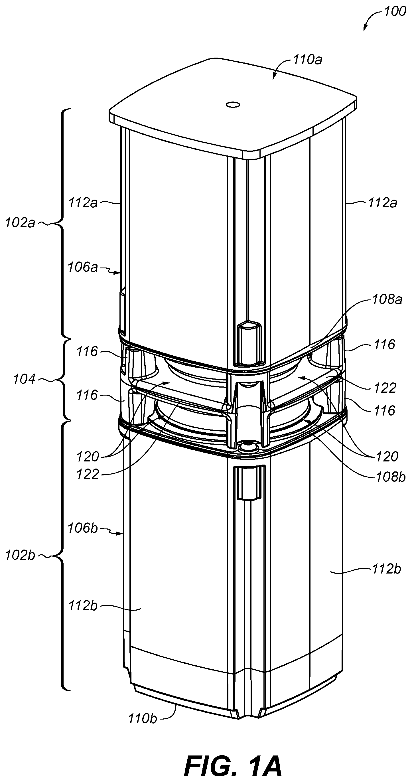
This application is a continuation of U.S. patent application Ser. No. 15/221,906, filed Jul. 28, 2016, and titled, “Omni-Directional Speaker System and Related Devices and Methods,” which is a continuation-in-part of U.S. patent application Ser. No. 14/643,216, filed Mar. 10, 2015, now U.S. Pat. No. 9,544,681, granted Jan. 10, 2017, and titled “Acoustic Deflector for Omni-Directional Speaker System,” which claims benefit from U.S. Provisional Patent Application No. 62/110,493, filed Jan. 31, 2015 and titled “Acoustic Deflector for Omni-Directional Speaker System,” the contents of which are incorporated herein by reference. Conventional acoustic deflectors in speaker systems can exhibit artifacts in the acoustic spectrum due to acoustic modes present between an acoustic driver and an acoustic deflector. This disclosure relates to an acoustic deflector for equalizing the resonant response for an omni-directional speaker system. In one aspect, an omni-directional speaker system includes a deflector sub-assembly and a pair of acoustic sub-assemblies. The deflector sub-assembly includes a pair of diametrically opposed acoustic deflectors. Each of the acoustic sub-assemblies includes an acoustic driver for radiating acoustic energy toward an associated one of the acoustic deflectors. The acoustic sub-assemblies are coupled together via the deflector sub-assembly. Implementations may include one of the following features, or any combination thereof. In some implementations, each of the acoustic sub-assemblies includes an acoustic enclosure, and the deflector sub-assembly is coupled to the acoustic sub-assemblies so as to enable formation of respective acoustic seals at respective junctions between associated ones of the acoustic drivers and the acoustic enclosures. In certain implementations, the pair of acoustic sub-assemblies includes a first acoustic sub-assembly. The first acoustic sub-assembly includes a first acoustic driver and a first acoustic enclosure. The first acoustic driver is coupled to the first acoustic enclosure via a first pair of fasteners partially forming a first acoustic seal at a junction between the first acoustic driver and the first acoustic enclosure. The deflector sub-assembly is coupled to the first acoustic sub-assembly via a second pair of fasteners so as to complete the first acoustic seal. In some examples, each fastener of the second pair of fasteners passes through respective holes in the deflector sub-assembly and the first acoustic driver, and threadingly engages the first acoustic enclosure. In certain examples, the pair of acoustic sub-assemblies also includes a second acoustic sub-assembly. The second acoustic sub-assembly includes a second acoustic driver and a second acoustic enclosure. The second acoustic driver is coupled to the second acoustic enclosure via a third pair of fasteners partially forming a second acoustic seal at a junction between the second acoustic driver and the second acoustic enclosure. The deflector sub-assembly is coupled to the second acoustic sub-assembly via a fourth pair of fasteners so as to complete the second acoustic seal. In some cases, each fastener of the fourth pair of fasteners passes through respective holes in the second acoustic enclosure and the second acoustic driver, and threadingly engages the deflector sub-assembly. In certain cases, the deflector sub-assembly includes a plurality of vertical legs, and the deflector sub-assembly is coupled to the acoustic sub-assemblies via the vertical legs. In some implementations, the deflector sub-assembly is coupled to a first one of the acoustic sub-assemblies via a first diametrically opposed pair of the vertical legs, and the deflector sub-assembly is coupled to a second one of the acoustic sub-assemblies via a second diametrically opposed pair of the vertical legs. In certain implementations, the pair of diametrically opposed acoustic deflectors together define a common (shared) acoustic chamber. In some examples, the deflector sub-assembly includes an acoustically absorbing member disposed within the acoustic chamber. In certain examples, the acoustically absorbing member is held in a compressed state by the pair of diametrically opposed acoustic deflectors. In some cases, the compression of the acoustically absorbing member changes an acoustic property of the acoustically absorbing member. Another aspect features a method of assembling an omni-directional acoustic assembly. The method includes coupling a deflector sub-assembly that includes a pair of diametrically opposed acoustic deflectors to a first acoustic sub-assembly that includes a first acoustic enclosure and a first acoustic driver such that the first acoustic driver is arranged to radiate acoustic energy toward a first one of the acoustic deflectors. The method also includes coupling the deflector sub-assembly to a second acoustic sub-assembly that includes a second acoustic driver and a second acoustic enclosure such that the second acoustic driver is arranged to radiate acoustic energy toward a second one of the acoustic deflectors. Implementations may include one of the above and/or below features, or any combination thereof. In some implementations, the step of coupling the deflector sub-assembly to the first acoustic sub-assembly completes a first acoustic seal at a junction between the first acoustic driver and the first acoustic enclosure. In certain implementations, the step of coupling the deflector sub-assembly to the first acoustic sub-assembly includes passing a fastener through respective holes in the deflector sub-assembly and the first acoustic driver, and screwing the fastener into threaded engagement with the first acoustic enclosure. In some examples, the step of coupling the deflector sub-assembly to the second acoustic sub-assembly comprises passing a fastener through respective holes in the second acoustic enclosure and the second acoustic driver, and screwing the fastener into threaded engagement with the deflector sub-assembly. In certain examples, the step of coupling the deflector sub-assembly to the first acoustic sub-assembly includes passing a first pair of fasteners through respective holes in the deflector sub-assembly and the first acoustic driver, and screwing the first pair of fasteners into threaded engagement with the first acoustic enclosure; and the step of coupling the deflector sub-assembly to the second acoustic sub-assembly includes passing a second pair of fasteners through respective holes in the second acoustic enclosure and the second acoustic driver, and screwing the second pair of fasteners into threaded engagement with the deflector sub-assembly. Another aspect provides an acoustic deflector sub-assembly that includes a pair of diametrically opposed omni-directional acoustic deflectors, and a first pair of vertical legs for mounting to a first acoustic sub-assembly such that a first one of the acoustic deflectors is arranged to deflect acoustic energy radiated from the first acoustic sub-assembly. The acoustic deflector sub-assembly also includes a second pair of vertical legs for mounting to a second acoustic sub-assembly such that a second one of the acoustic deflectors is arranged to deflect acoustic energy radiated from the second acoustic sub-assembly. Implementations may include one of the above and/or below features, or any combination thereof. In some implementations, each of the omni-directional acoustic deflectors includes an acoustically reflective body that has a truncated conical shape including a substantially conical outer surface, a top surface, and a cone axis. Each acoustically reflective body has an opening in the top surface centered on the cone axis. An acoustically absorbing material is disposed at the openings in the top surfaces of the acoustically reflective bodies. In certain implementations, the respective cone axes of the omni-directional acoustic deflectors are coaxial. According to yet another aspect, an acoustic deflector sub-assembly includes a pair of diametrically opposed omni-directional acoustic deflectors. Each of the omni-directional acoustic deflectors includes an acoustically reflective body have a truncated conical shape including a substantially conical outer surface, a top surface and a cone axis. Each acoustically reflective body having an opening in the top surface centered on the cone axis. The acoustically reflective bodies together define a shared acoustic chamber that is acoustically coupled to the openings in the top surfaces of the acoustically reflective bodies. Implementations may include one of the above and/or below features, or any combination thereof. In some implementations, the acoustically reflective bodies include recesses disposed about their respective substantially conical outer surfaces. Multiple benefits are known for omni-directional speaker systems. These benefits include a more spacious sound image when the speaker system is placed near a boundary, such as a wall within a room, due to reflections. Another benefit is that the speaker system does not have to be oriented in a particular direction to achieve optimum high frequency coverage. This second advantage is highly desirable for mobile speaker systems where the speaker system and/or the listener may be moving. Each acoustic enclosure 108 includes a base 110 The deflector sub-assembly includes 104 a pair of diametrically opposing omni-directional acoustic deflectors 114 Acoustic energy generated by the acoustic drivers 108 propagates toward the deflector sub-assembly 104 and is deflected into a nominal horizontal direction (i.e., a direction substantially normal to the motion axes of the acoustic drivers 108), by respective substantially conical outer surfaces of the acoustic deflectors 114. There are eight substantially rectangular openings 120. Each opening 120 is defined by one of the acoustic sub-assemblies, a base 122 of the deflector sub-assembly 104, and a pair of the vertical legs 116. These eight openings 120 are acoustic apertures which pass the horizontally propagating acoustic energy. It should be understood that the propagation of the acoustic energy in a given direction includes a spreading of the propagating acoustic energy, for example, due to diffraction. As shown in In the illustrated example, each of the omni-directional acoustic deflectors 114 includes two features which may contribute to an improvement of the acoustic spectrum. First, there are acoustically absorbing regions disposed along the acoustically reflecting surface. As shown in In the illustrated implantation, the acoustically absorbing material 126 is foam (e.g., melamine foam). Notably, the bodies of the acoustic deflectors 114 together form a common body cavity 128 (a/k/a acoustic chamber), which, in the illustrated example, is filled with a single volume of foam such that the foam is adjacent to, or extends into, the openings. Alternatively, a separate foam element may be disposed at each opening so that only a portion of the body cavity 128 is occupied by foam. In one implementation, the foam present at each of the central openings 124 is at one end of a cylindrically-shaped foam element disposed within the body cavity 128. In some cases, the foam element is oversized and is compressed between the bodies of the acoustic deflectors 114 to achieve the desired acoustic properties (e.g., the desired acoustic absorptivity). The body cavity 128, together with the openings 124, serves as a Helmholtz resonator (i.e., a shared, or dual, Helmholtz resonator) for attenuating a certain acoustic mode. By combining the volume between the two acoustic deflectors, there is more volume to work with in terms of trapping of the energy making the Helmholz resonator work. So sharing a common acoustic chamber effectively increases the volume that is available to each one of the deflectors individually, thereby increasing the amount of volume to kill the acoustic mode. The second feature of the acoustic deflectors 114 that may contribute to an improvement in the acoustic spectrum is the presence of recesses 130 Alternatively or additionally, the recesses 130 may correspond with/to features of the acoustic driver. That is the recesses may be included to accommodate movement of features of the acoustic driver (e.g., movement of a diaphragm of the acoustic driver) relative to the omni-directional acoustic deflectors. The first acoustic driver 108 Next, referring to Referring to With reference to Referring to Finally, first and second end caps 230 The second end cap 230 As shown in In general, omni-directional acoustic deflectors according to principles described herein act as an acoustic smoothing filter by providing a modified acoustic resonance volume between the acoustic driver and the acoustic deflector. It will be appreciated that adjusting the size and locations of the acoustically absorbing regions allows for the acoustic spectrum to be tuned to modify the acoustic spectrum. Similarly, the profile of the acoustically reflecting surface may be non-linear (i.e., vary from a perfect conical surface) and defined so as to modify the acoustic spectrum. In addition, non-circularly symmetric extensions in the acoustically reflecting surface, such as the radial extensions described above, can be utilized to achieve an acceptable acoustic spectrum. A number of implementations have been described. Nevertheless, it will be understood that additional modifications may be made without departing from the scope of the inventive concepts described herein. An omni-directional speaker system includes a deflector sub-assembly and a pair of acoustic sub-assemblies. The deflector sub-assembly includes a pair of diametrically opposed acoustic deflectors. Each of the acoustic sub-assemblies includes an acoustic driver for radiating acoustic energy toward an associated one of the acoustic deflectors. The acoustic sub-assemblies are coupled together via the deflector sub-assembly. 1. An acoustic deflector sub-assembly, comprising
a pair of diametrically opposed omni-directional acoustic deflectors; wherein each of the omni-directional acoustic deflectors comprises an acoustically reflective body having a truncated conical shape including a substantially conical outer surface, a top surface and a cone axis, each acoustically reflective body having an opening in the top surface centered on the cone axis, and wherein the acoustically reflective bodies together define a shared acoustic chamber that is acoustically coupled to the openings in the top surfaces of the acoustically reflective bodies. 2. The acoustic deflector sub-assembly of 3. The acoustic deflector sub-assembly of 4. The acoustic deflector sub-assembly of 5. The acoustic deflector sub-assembly of 6. The acoustic deflector sub-assembly of a first pair of vertical legs for mounting to a first acoustic sub-assembly such that a first one of the acoustic deflectors is arranged to deflect acoustic energy radiated from the first acoustic sub-assembly; and a second pair of vertical legs for mounting to a second acoustic sub-assembly such that a second one of the acoustic deflectors is arranged to deflect acoustic energy radiated from the second acoustic sub-assembly. 7. The acoustic deflector sub-assembly of 8. The acoustic deflector sub-assembly of 9. The acoustic deflector sub-assembly of 10. The acoustic deflector sub-assembly of 11. A method of forming an acoustic deflector sub-assembly, the method comprising
coupling a pair of diametrically opposed omni-directional acoustic deflectors; wherein each of the omni-directional acoustic deflectors comprises an acoustically reflective body having a truncated conical shape including a substantially conical outer surface, a top surface and a cone axis, each acoustically reflective body having an opening in the top surface centered on the cone axis, and wherein the acoustically reflective bodies together define a shared acoustic chamber that is acoustically coupled to the openings in the top surfaces of the acoustically reflective bodies. 12. The method of 13. The method of 14. The method of 15. The method of 16. The method of mounting a first pair of vertical legs to a first acoustic sub-assembly such that a first one of the acoustic deflectors is arranged to deflect acoustic energy radiated from the first acoustic sub-assembly; and mounting a second pair of vertical legs to a second acoustic sub-assembly such that a second one of the acoustic deflectors is arranged to deflect acoustic energy radiated from the second acoustic sub-assembly. 17. The method of 18. The method of 19. The method of 20. The method of RELATED APPLICATION
BACKGROUND
SUMMARY
BRIEF DESCRIPTION OF THE DRAWINGS
DETAILED DESCRIPTION