PNEUMATIC TIRE
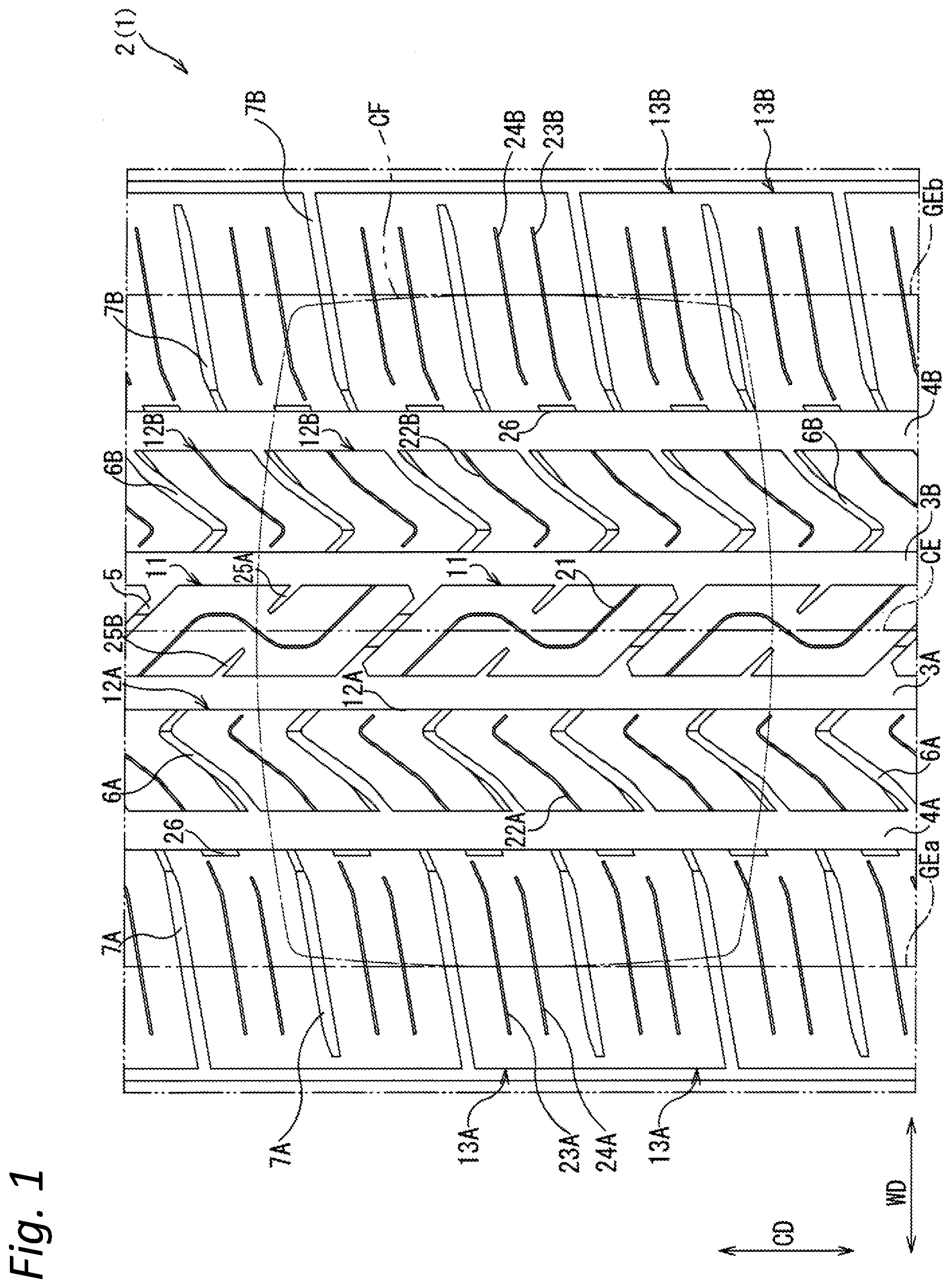
This application claims priority of Japanese Patent Application No. 2018-125051 filed on Jun. 29, 2018, the content of which is incorporated herein by reference. The present invention relates to a pneumatic tire. The pneumatic tire disclosed in Japanese Patent No. 6104215 includes a shoulder block on which a sipe extending in the tire width direction is formed. The sipe formed on the shoulder block improves the traction performance on the snowy road surface and contributes to the improvement of the traveling performance on the snowy road surface. However, conventional pneumatic tires having a shoulder block on which a sipe is formed, including those disclosed in Japanese Patent No. 6104215, still have room for improvement in terms of improving braking performance on the dry road surface and wear-resistant performance while ensuring traveling performance on the snowy road surface. An object of the present invention is to provide a pneumatic tire that achieves improvement in braking performance on the dry road surface and improvement in wear-resistant performance while ensuring traveling performance on the snowy road surface. One aspect of the present invention provides a pneumatic tire including: a shoulder main groove formed on a tread portion so as to extend in a tire circumferential direction on a grounding end side; a plurality of lateral grooves formed on the tread portion so as to extend in a direction intersecting with the tire circumferential direction; a shoulder block defined by the shoulder main groove and the lateral grooves; a first shoulder sipe that is formed on the shoulder block, extends from the grounding end toward the shoulder main groove, and has an end portion that terminates in the shoulder block; and a second shoulder sipe that is formed in the shoulder block at an interval in the tire circumferential direction with respect to the first shoulder sipe, extends from the grounding end toward the shoulder main groove, and has an end portion that terminates in the shoulder block, wherein the end portion of the first shoulder sipe and the end portion of the second shoulder sipe are different in position of a tire width direction. Specifically, the difference between the distance from the end portion of the first shoulder sipe to the shoulder main groove and the distance from the end portion of the second shoulder sipe to the shoulder main groove is 2 mm or more and 15 mm or less. Providing the first and second shoulder sipes on the shoulder block improves the traction performance on the snowy road surface and ensures the traveling performance on the snowy road surface. In addition, since the end portions terminating in the shoulder blocks included in the first and second shoulder sipes are different in position of the tire width direction, it is possible to avoid the ground contact pressure in the shoulder block from concentrating in one position in the tire width direction, that is, in one straight line extending in the tire circumferential direction. As a result, braking performance on the dry road surface can be improved. The end portions of the first and second shoulder sipes terminate in the shoulder block. That is, both the first and second shoulder sipes are not in communication with the shoulder main groove. Therefore, the rigidity of the shoulder block can be ensured, and the wear-resistant performance can be improved. Each of the first and second shoulder sipes may have a first portion that includes the end portion and extends in a first direction and a second portion that is continuous to the first portion and extends at an angle different from the first direction. By having the first portion and the second portion that extend at different angles, it is possible to avoid matching between the first and second shoulder sipes with the grounding shape, and it is possible to reduce impact noise when traveling on the dry road surface in particular. That is, such the constitution can improve noise performance. Specifically, the angle formed between the first portion and the tire width direction may be 10 degrees or more and 40 degrees or less. The angle formed between the second portion and the tire width direction may be 0 degrees or more and 30 degrees or less. The length of the first portion may be 5% or more and 30% or less of the length of the second portion. The pneumatic tire may include a recess formed in a portion facing the shoulder main groove of the shoulder block. This constitution can further improve traction performance on the snowy road surface. The recess may be provided at a position corresponding to a region between the end portion of the first shoulder sipe and the end portion of the second shoulder sipe in the tire circumferential direction. Providing the recess portion at such the position homogenizes the distribution of the edge component included in the shoulder block. That is, uneven distribution of the edge component in the shoulder block can be avoided. As a result, a better traction performance is obtained on the snowy road surface. The pneumatic tire according to the present invention can realize improvement in braking performance on the dry road surface and improvement in wear-resistant performance while ensuring traveling performance on the snowy road surface. The foregoing and the other features of the present invention will become apparent from the following description and drawings of an illustrative embodiment of the invention in which: An embodiment of the present invention will be described with reference to the accompanying drawings. In the following description, In the present description, the term “groove” means a notch having a certain width of, for example, about 2.5 mm or more, and the term “sipe” means a notch thinner than “groove” and having a width of, for example, 0.8 mm or more and 1.5 mm or less. A pneumatic tire 1 (hereinafter simply referred to as a tire) according to the embodiment of the present invention is an all-weather, all-season tire that is suitable for traveling on a dry road surface but can also travel on a snowy road surface. In the figure, a reference symbol CD indicates a tire circumferential direction, and a reference symbol WD indicates a tire width direction. In the figure, a reference symbol CE indicates a center line in the tire width direction of a tread portion of the tire 1. Reference symbols GEa and GEb indicate grounding ends of a tread portion 2. A reference symbol CF indicates a grounding shape. The grounding ends GEa and GEb and the grounding shape CF are under the condition of 220 kPa/490 kgf. The tread portion 2 is formed with four main grooves 3A, 3B, 4A, and 4B each extending in the tire circumferential direction. In the present embodiment, each of the main grooves 3A, 3B, 4A, and 4B is a linear groove having a certain groove width. The main grooves 3A, 3B, 4A, and 4B may have distribution in the groove width in the tire circumferential direction, or may be meandering or zigzag grooves. The center main grooves 3A and 3B are arranged adjacent to each other across the center line CE. The shoulder main grooves 4A and 4B are arranged on the grounding end GEa and GEb sides. The shoulder main groove 4A is arranged on an outer side in the tire width direction with respect to the center main groove 3A, that is, adjacent to the grounding end GEa side. The shoulder main groove 4B is arranged on an outer side in the tire width direction with respect to the center main groove 3B, that is, adjacent to the grounding end GEb side. The tread portion 2 is provided with five types of lateral grooves (lag grooves) 5, 6A, 6B, 7A, and 7B each extending generally in the tire width direction. A plurality of the center lateral grooves 5 are provided at regular intervals in the tire circumferential direction. Both end portions of each of the center lateral grooves 5 are in communication with the center main grooves 3A and 3B. Each of the center lateral grooves 5 is linear as a whole, and is inclined with respect to the tire width direction so as to be downward-sloping in the figure. Each of the center lateral grooves 5 includes a first portion 5 A plurality of the mediate lateral grooves 6A are provided at regular intervals in the tire circumferential direction. Each of the mediate lateral grooves 6A includes a first portion 6 A plurality of the shoulder lateral grooves 7A are provided at regular intervals in the tire circumferential direction. Each of the shoulder lateral grooves 7A includes a first portion 7 One center block 11 is defined by the center main grooves 3A and 3B and the two center lateral grooves 5 adjacent in the tire circumferential direction. A plurality of the center blocks 11 are aligned in the tire circumferential direction. Each of the center blocks has a parallelogram shape that is elongated in the tire circumferential direction as viewed in a tire radial direction. One mediate block 12A is defined by the center main groove 3A, the shoulder main groove 4A, and the two mediate lateral grooves 6A adjacent in the tire circumferential direction. A plurality of the mediate blocks 12A are aligned in the tire circumferential direction. As described above, since the mediate lateral groove 6A has a bent shape, the individual mediate blocks 12A also have a bent shape as viewed in the tire radial direction. That is, each of the mediate blocks 12A has, on the center main groove 3A side, a first portion 12 One shoulder block 13A is defined by the shoulder main groove 4A and the two shoulder lateral grooves 7A adjacent in the tire circumferential direction. A plurality of the shoulder blocks 13A are aligned in the tire circumferential direction. As described above, since the shoulder lateral grooves 7A have a slightly bent shape, each of the shoulder blocks 13A also has a first portion 13 The mediate block 12A and the shoulder block 13A are provided at the identical pitch in the tire circumferential direction. On the other hand, the center block 11 is provided in the tire circumferential direction at a pitch twice the pitch of the mediate block 12A and the shoulder block 13A. That is, the one center block 11 is provided for the two mediate blocks 12A and the two shoulder blocks 13A. Therefore, as described above, the mediate block 12A and the shoulder block 13A have a shape elongated in the tire width direction, whereas the center block 11 has a shape elongated in the tire circumferential direction. The pattern of the tread portion 2 of the present embodiment has a symmetry with respect to the center line CE. That is, the shape and structure of the mediate lateral groove 6B, the shoulder lateral groove 7B, the mediate block 12B, and the shoulder block 13B on the right side (grounding end GEb side) with respect to the center line CE in the figure are identical to those of the mediate lateral groove 6A, the shoulder lateral groove 7A, the mediate block 12A, and the shoulder block 13A, except being reversed upside down in the figure. In the figure, the elements included in the mediate lateral groove 6B and the like are given similar or identical reference symbols as the elements included in the mediate lateral groove 6A and the like. In the following description, unless otherwise necessary, the mediate lateral groove 6A, the shoulder lateral groove 7A, the mediate block 12A, and the shoulder block 13A on the left side (grounding end GEa side) with respect to the center line CE in the figure will be described. One center sipe 21 is formed in each of the center blocks 11. The center sipe 21 extends from one side portion to the other side portion of the center block 11 in the tire width direction and crosses the center block 11 in the tire width direction. The center sipe 21 has a reverse S-shape extending in the tire circumferential direction as a whole, and is provided, in a continuous manner, with a first widthwise protrusion portion 21 One mediate sipe 22A is formed in each of the mediate blocks 12A. The mediate sipe 22A includes a first portion 22 The mediate sipe 12A overall has a bent shape projecting upward in the tire circumferential direction in the figure. On the other hand, the mediate sipe 22B formed in the mediate block 12B has a bent shape projecting in the opposite direction to the mediate sipe 12A, i.e., downward in the tire circumferential direction in the figure. Two shoulder sipes 23A and 24A are formed in each of the shoulder blocks 13A. The shoulder sipe 23A overall extends from the grounding end GEa toward the shoulder main groove 3A. The shoulder sipe 23A includes a first portion 23 The shoulder sipe 24A overall extends from the grounding end GEa toward the shoulder main groove 3A. The shoulder sipe 24A includes a first portion 24 The other structure of the shoulder block 13A will be described later. Next, the center block 11 will be further described with reference to As described above, one center block 11 is provided with the two mediate blocks 12A and the two shoulder blocks 13A, and has a shape elongated in the tire circumferential direction. Specifically, a length (dimension in the tire circumferential direction) BL1 of the center block 11 is set to be not less than twice and not more than 5 times a width (dimension in the tire width direction) BW1 of the center block 11. As described above, the center sipe 21 formed in the center block 11 includes the first widthwise protrusion portion 21 The center sipe 21 has four bent portions 21 In the figure, a distance DC1 from the upper end of the center block 11 to the end portion of the first linear portion 21 As described above, the center sipe 21 has an amplitude in the tire width direction that is constituted by the first widthwise protrusion portion 21 The center sipe 21 does not have a bent portion. The both end portions of the center sipe 21 are positioned in the range of 55% or more and 85% or less of the length BL1 of the center block 11 from the both end portions of the center block 11 in the tire circumferential direction, and positioned relatively in proximity to the both end portions of the center block 11 in the tire circumferential direction. The center sipe 21 has a large amplitude, that is, an amplitude of an amount of 60% or more and 85% or less of the width BW1 of the center block. The center sipe 21 has a smooth, large S-shape extending generally over the entire surface of the center block 11. Therefore, the ground contact pressure at the center block 11 is dispersed without being concentrated at one position, and hence the braking performance on the dry road surface can be improved. The two portions of the center block 11 divided by the center sipe 21 support each other at the time of braking, thereby suppressing collapse. As a result, braking performance and uneven wear-resistant performance can be improved. The center block 11 is provided with notches 25A and 25B extending from both side portions in the tire width direction. The notches 25A and 25B have a tapered shape as viewed in the tire radial direction. The tips of the notches 25A and 25B are positioned between the first widthwise protrusion portion 21 Next, the mediate block 12A will be further described with reference to As described above, the mediate sipe 22A formed in the mediate block 12A includes the first portion 22 In order to avoid matching with the grounding shape CF while ensuring that the edge component functions on the snowy road surface, it is preferable to set the mediate sipe 22A as follows. First, an inclination angle θm1 of the first portion 22 As mentioned above, the end portion of the first portion 22 Next, the shoulder block 13A will be further described with reference to As described above, the shoulder sipes 23A and 24A are provided in the shoulder block 13A. The end portion of the shoulder sipe 23A on the shoulder main groove 4A side, i.e., the end portion of the first portion 23 Providing the shoulder sipes 23A and 24A on the shoulder block 13A improves the traction performance on the snowy road surface and ensures the traveling performance on the snowy road surface. Since the end portion of the first portion 23 The first portion 23 In order to avoid matching with the grounding shape CF while ensuring that the edge component functions on the snowy road surface, it is preferable to set the shoulder sipes 23A and 24A as follows. First, an inclination angle θs1 of the first portions 23 The shoulder block 13A is provided with a recess portion 26 in a portion facing the shoulder main groove 4A, i.e., a portion where the top wall and the side wall of the shoulder block 13A merge. A depth Dp of the recess portion 26 is set to, for example, 3 mm or more and 10 mm or less. With reference also to The recess portion 26 is provided at a position corresponding to the region between the end portion of the first portion 23 An alternative shoulder block 13A shown in In another alternative shoulder block 13A shown in In yet another alternative shoulder block 13A shown in A shoulder block is formed with a first shoulder sipe and a second shoulder sipe that extend from a grounding end toward a shoulder main groove and have an end portion that terminates in the shoulder block. The end portion of the first shoulder sipe and the end portion of the second shoulder sipe are different in position of a tire width direction. 1. A pneumatic tire, comprising:
a shoulder main groove formed on a tread portion so as to extend in a tire circumferential direction on a grounding end side; a plurality of lateral grooves formed on the tread portion so as to extend in a direction intersecting with the tire circumferential direction; a shoulder block defined by the shoulder main groove and the lateral grooves; a first shoulder sipe that is formed on the shoulder block, extends from the grounding end toward the shoulder main groove, and has an end portion that terminates in the shoulder block; and a second shoulder sipe that is formed in the shoulder block at an interval in the tire circumferential direction with respect to the first shoulder sipe, extends from the grounding end toward the shoulder main groove, and has an end portion that terminates in the shoulder block, wherein the end portion of the first shoulder sipe and the end portion of the second shoulder sipe are different in position of a tire width direction. 2. The pneumatic tire according to 3. The pneumatic tire according to each of the first and second shoulder sipes has
a first portion that includes the end portion and extends in a first direction, and a second portion that is continuous to the first portion and extends at an angle different from the first direction. 4. The pneumatic tire according to each of the first and second shoulder sipes has
a first portion that includes the end portion and extends in a first direction, and a second portion that is continuous to the first portion and extends at an angle different from the first direction. 5. The pneumatic tire according to 6. The pneumatic tire according to 7. The pneumatic tire according to 8. The pneumatic tire according to 9. The pneumatic tire according to 10. The pneumatic tire according to 11. The pneumatic tire according to 12. The pneumatic tire according to 13. The pneumatic tire according to 14. The pneumatic tire according to 15. The pneumatic tire according to 16. The pneumatic tire according to 17. The pneumatic tire according to 18. The pneumatic tire according to CROSS-REFERENCE TO RELATED APPLICATIONS
BACKGROUND OF THE INVENTION
Technical Field
Related Art
SUMMARY
BRIEF DESCRIPTION OF THE DRAWINGS
DETAILED DESCRIPTION OF EMBODIMENTS