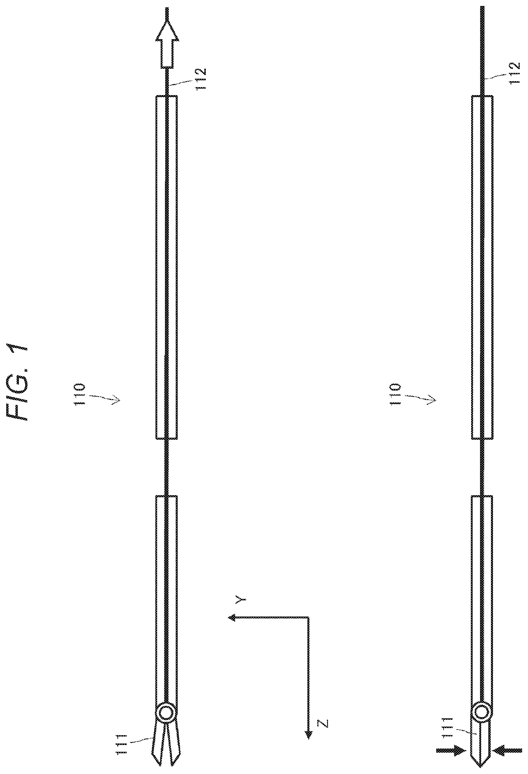
MEDICAL OPERATION SYSTEM, SURGICAL SYSTEM, SURGICAL INSTRUMENT, AND EXTERNAL FORCE SENSING SYSTEM
The technology disclosed in the present specification to provide a medical operation system, a surgical system, a surgical instrument, and an external force sensing system that detect a force acting on an end effector. Advances in the robotics technologies in recent years are remarkable, and robots are widely used in work sites in various industrial fields. For example, in a master-slave robot system, a person (an operator) handles a master arm in front of the person, and a slave arm located at a remote place traces the movement of the master arm. Thus, remote control of a manipulator can be realized. Master-slave robot systems such as medical robots are used in industrial fields where fully autonomous operations by computer control are still difficult. For example, “da Vinci Surgical System (da Vinci)” manufactured by Intuitive Surgical Inc. of the United States is the first master-slave surgical robot that was developed for endoscopic surgery such as abdominal surgery and thoracic surgery. The surgical robot, “da Vinci”, is equipped with various kinds of robot forcipes, and further, the practitioner can perform surgery through remote control of the slave arm by recognizing the surgical field while watching a 3D monitor screen. For this reason, several proposals have also been made for medical robotics systems capable of detecting a force acting on an end effector such as a gripping unit (gripper) (see Non-Patent Document 1, for example). In a surgical robot to be used for endoscopic surgery, it is necessary to reduce the size of the configuration of the end effector, and a drive mechanism is normally used. By this drive mechanism, a driving force generated by a drive unit such as a motor disposed at a distance from the end effector is transmitted through a cable, to open and close the end effector. In the above described force-detectable medical robotics system, a force sensor is disposed between the end effector and the drive unit that drives the end effector. In such a configuration, the tractive force of the cable for opening and closing the end effector interferes with an external force applied in the long axis direction of the end effector, for example. This might lower the sensitivity of the force sensor, or make calibration difficult. Non-Patent Document 1: Ulrich Seibold et al., “Prototype of Instrument for Minimally Invasive Surgery with 6-Axis Force Sensing Capability”, Proceedings of the 2005 IEEE International Conference on Robotics and Automation, pp. 498-503, Barcelona, Spain, April 2005 An object of the technology disclosed in the present specification is to provide an excellent medical operation system, a surgical system, a surgical instrument, and an external force sensing system that are capable of detecting a force acting on an end effector in a preferred manner. The technology disclosed in the present specification is made in view of the above problems, and a first aspect thereof is a medical operation system that includes: an inner slave having an end effector; an outer slave into which the inner slave is inserted, the outer slave supporting the inner slave at a position that allows the end effector to protrude outward from an end of the outer slave; a strain detection unit that detects strain generated in the outer slave; and a processing unit that calculates a force acting on the end effector in a living subject, on the basis of a result of detection performed by the strain detection unit. It should be noted that the term “system” means a logical assembly of a plurality of devices (or functional modules that realize specific functions), and the respective devices or functional modules are not necessarily in a single housing. Here, the outer slave has a bending portion that bends in a long axis direction, and the strain detection unit is disposed on a distal end side than the bending portion. Further, the outer slave has a structure decoupled from the inner slave, and a cable for pulling the end effector is inserted together with the inner slave into the outer slave. The strain detection unit includes strain detection elements disposed at two positions on respective opposite sides in two directions perpendicular to the long axis direction of the outer slave. Specifically, the strain detection unit includes the strain detection elements including FBG sensors formed at the two positions on optical fibers attached to the respective opposite sides in the two directions perpendicular to the long axis direction of the outer slave. Further, dummy FBG sensors are formed in the optical fibers. Further, the outer slave has a shape that allows stress to concentrate at the two positions at which the strain detection elements are disposed. The processing unit then calculates a translational force and a moment acting on the end effector, on the basis of strains at the two positions on the respective opposite sides in the two directions perpendicular to the long axis direction of the outer slave, the strains having been detected by the strain detection elements. The processing unit also calculates a translational force and a moment acting on the end effector, on the basis of strains at the two positions on the respective opposite sides in the two directions perpendicular to the long axis direction of the outer slave, the strains having been detected by the strain detection elements. Further, the processing unit removes a strain component caused by a temperature change from the average value, and calculates a force acting in the long axis direction of the end effector. Specifically, the processing unit removes a strain component caused by a temperature change from a result of detection performed by the FBG sensors, on the basis of wavelength changes of the dummy FBG sensors. Further, a second aspect of the technology disclosed in the present specification is a surgical system that includes: a master device; and a slave device remotely controlled by the master device, the slave device including an inner slave having an end effector, an outer slave into which the inner slave is inserted, the outer slave supporting the inner slave at a position that allows the end effector to protrude outward from an end of the outer slave, a strain detection unit that detects strain generated in the outer slave, a processing unit that calculates a force acting on the end effector in a living subject, on the basis of a result of detection performed by the strain detection unit, and an output unit that outputs a result of processing performed by the processing unit, to the master device. Further, a third aspect of the technology disclosed in the present specification is a surgical instrument that includes: an inner slave having an end effector; an outer slave into which the inner slave is inserted, the outer slave supporting the inner slave at a position that allows the end effector to protrude outward from an end of the outer slave; a strain detection unit that detects strain generated in the outer slave; and a transmission unit that transmits a result of detection performed by the strain detection unit. Further, a fourth aspect of the technology disclosed in the present specification is an external force sensing system that includes: an inner slave having an end effector; an outer slave into which the inner slave is inserted, the outer slave supporting the inner slave at a position that allows the end effector to protrude outward from an end of the outer slave; a strain detection unit that detects strain generated in the outer slave; and a processing unit that calculates a force acting on the end effector, on the basis of a result of detection performed by the strain detection unit. According to the technology disclosed in the present specification, it is possible to provide an excellent medical operation system, a surgical system, a surgical instrument, and an external force sensing system that are capable of detecting a force acting on an end effector in a preferred manner. Note that the advantageous effects described in the present specification are merely examples, and the advantageous effects of the present invention are not limited to them. Furthermore, the present invention may exhibit additional advantageous effects, in addition to the above described advantageous effects. Other objects, features, and advantages of the technology disclosed in the present specification will be made apparent by the embodiments described below and the detailed descriptions with reference to the accompanying drawings. The following is a detailed description of embodiments of the technology disclosed in the present specification, with reference to the drawings. In the description below, an X-Y-Z coordinate system is set, and the long axis direction of the gripping mechanism unit 110 is the Z-axis in the X-Y-Z coordinate system. Accordingly, the leftward direction in the drawing is the Z-axis, a direction perpendicular to the drawing is the X-axis, and a vertical direction in the drawing is the Y-axis. The gripping mechanism unit 110 is equivalent to a treatment tool also called a “biopsy forceps”, and has an end effector 111 at its tip. The end effector 111 includes a pair of blades that can be opened and closed. The end effector 111 can be opened and closed by a tractive force transmitted from a drive unit (not shown) such as a motor via a cable 112, and grip an object such as a body tissue or a surgical instrument. In the example shown in Meanwhile, the outer casing member 120 is a guide tube equivalent to a “trocar”. The outer casing member 120 includes a hollow cylindrical structure, and is inserted into a body cavity such as an abdominal cavity or a chest cavity, to guide the gripping mechanism unit 110. In a body cavity, it is not necessarily possible to move the gripping mechanism unit 110 (or the end effector 111) straight from the position at which the outer casing member 120 is inserted to the position at which the object to be gripped exists. For this reason, the outer casing member 120 has a bending structure so that it becomes possible to bypass an obstacle or the like and reach the object to be gripped from the position at which the outer casing member 120. Specifically, as can be seen from The surgical system 100 is equivalent to a biopsy forceps that is detachably mounted on a robot arm of a medical or surgical robot to be used for performing ophthalmic surgery, brain surgery, or endoscopic surgery such as abdominal surgery or thoracic surgery in a minimally invasive manner, for example. In a case where the surgical system 100 is a slave in a master-slave robot system, a drive unit for pulling the biopsy forceps, which is the end effector 111, with the cable 112, and a drive unit for pulling the first outer casing 121 with the cable 124 are activated in accordance with instructions from the master. Further, in the master-slave robot system, it is preferable to give a feedback of information about the position of the slave arm, the external force to be applied to the slave arm, and the like, so that the operator can perform remote control on the slave arm accurately and efficiently with the master arm, without damaging the target object. Although not shown in the drawings, the surgical system 100 may also be designed so that the root of the second outer casing 122 is also rotatably supported by the tip of a third outer casing (not shown), and rotates by virtue of a tractive force of a cable. The first outer casing 121 and the second outer casing 122 are guide tubes. Each of the guide tubes has a hollow cylindrical shape, and allows the gripping mechanism unit 110 to be inserted thereinto, to guide the gripping mechanism unit 110 in a body cavity like a “trocar”. An opening 125 for letting out the tip of the gripping mechanism unit 110 is formed almost at the center of the end face on the distal end side of the first outer casing 121. The gripping mechanism unit 110 is inserted into the hollow first outer casing 121 from the proximal end side. A portion with a predetermined length from the tip of the gripping mechanism unit 110 including the end effector 111 then protrudes from the opening 125 toward the outside. In such a positional relationship, the gripping mechanism unit 110 is supported by a support 126 so as to be rotatable about the long axis, at the opening 125 of the end edge of the first outer casing 121. The surgical system 100 according to this embodiment can achieve one degree of freedom in gripping and one degree of freedom in bending, by combining the gripping mechanism unit 110 including the end effector 111 capable of opening and closing and the outer casing member 120 having a bending structure. Further, the gripping mechanism unit 110 as an inner slave has a degree of freedom in rotating about the long axis relative to the outer casing member 120 as an outer slave. Note that the gripping mechanism unit 110 as an inner slave and the first outer casing 121 as an outer slave are decoupled from each other. Although shown in a simplified manner in In a case where the surgical system 100 is applied to a slave device in a master-slave robot system, a force acting on the end effector 111 is detected, and may be used for force sense presentation to the operator on the master device side. Further, in a case where the end effector 111 opens and closes by virtue of a driving force transmitted via the cable 112, it is necessary to detect forces acting on the end effector 111, without interfering with the tractive force of the cable 112. The gripping mechanism unit 110 is supported by the support 126 so as to be rotatable about the long axis direction relative to the first outer casing 121 (as described above). The translational forces acting on the end effector 111 also act on the first outer casing 121. As a result, the first outer casing 121 generates a strain Δεin accordance with the translational forces Fx, Fy, and Fz acting on the end effector 111. The first outer casing 121 may be regarded as a cantilever that bends in the X and Y directions, and expands and contracts in the Z direction, with the first joint 123 being the fixed end. Therefore, in this embodiment, the first outer casing 121 is used as a strain generator, and a strain detection element is disposed at one or more locations on the outer periphery of the first outer casing 121. In the example shown in Specifically, at the position a, a pair of strain detection elements 501 First, the reason that the pair of strain detection elements 501 As shown in On the other hand, in a case where a pair of detection elements 721 and 722 are attached to opposite sides of the cantilever 701 in the Y direction, as shown in Because of this, the sum of the strain amounts detected by the pair of strain detection elements 501 Likewise, the sum of the strain amounts detected by the pair of strain detection elements 502 Next, the reason that the configuration in which the amounts of strain in the X and Y directions are detected at the two positions a and b different in the long axis direction of the first outer casing 121 is described. The translational force can be calculated from the amount of strain at one point on a cantilever, but the moment is not calculated from the amount of strain. On the other hand, the moment as well as the translational force can be calculated from the amounts of strain at two or more positions. Accordingly, with the configuration shown in The entire surgical system 100 can be regarded as being equipped with a sensor having 5 degrees of freedom (DOF) including the moments Mx and My about the two axes, in addition to the translational forces Fx, Fy, and Fz in the three directions. A tractive force of the cable 112 for opening and closing the end effector 111 acts on the gripping mechanism unit 110 inserted into the first outer casing 121. However, since the gripping mechanism unit 110 as the inner slave and the first outer casing 121 as the outer slave are decoupled from each other (described above), the tractive force of the cable 112 does not act on the first outer casing 121. Accordingly, the 5-DOF sensor mounted on the first outer casing 121 does not interfere with the tractive force of the cable 112 (in other words, the gripping force of the end effector 111), and thus, the acting forces Fx, Fy, and Fz of the 5-DOF acting on the end effector 110, and the moments Mx and My can be measured with high sensitivity. In addition to the above, there is an effect to reduce mechanical vibration noise, as the actual inertia in the stage after the 5-DOF sensor is reduced. In Meanwhile, strain detection elements widely known in the industry include capacitive sensors, semiconductor strain gauges, and foil strain gauges, any of which can be used as the strain detection elements 501 Here, an FBG sensor is a sensor formed by cutting a diffraction grating (a grating) along the long axis of an optical fiber, and is capable of detecting a change in the intervals between diffraction gratings due to expansion or contraction accompanying strain or temperature change caused by an acting force, and regarding the change in the intervals as a change in the wavelength of reflected light of incident light of a predetermined wavelength band (Bragg wavelength). The change in the wavelength detected from the FBG sensor can be then converted into strain, stress, or temperature change, which is the cause. In this embodiment, it is assumed that a signal processing unit that processes a detection signal is disposed at a location at a distance from the first outer casing 121 to which the strain detection elements 501 The structure of the first outer casing 121 designed to be easily deformed at the two measurement positions a and b, and a method of disposing the strain detection elements 501 As shown in the drawing, the outer periphery of the first outer casing 121 has a constricted structure that has concave portions at which the radius becomes gradually smaller at the two measurement positions a and b different in the long axis direction. On the other hand, the inner diameter of the first outer casing 121 is constant in the long axis direction, and the thickness of the concave portions is smaller. Accordingly, when a force is applied in at least one of the X or Y direction, the first outer casing 121 is easily deformed with stress concentrated at each of the measurement positions a and b, and can be used as a strain generator. The first outer casing 121 is formed with stainless steel (steel use stainless: SUS), a Co-Cr alloy, or a titanium-based material known as a metal-based material that excels in biocompatibility, for example, To form a strain generator in a portion of the structure as described above, it is preferable to manufacture the first outer casing 121, using a material having mechanical characteristics such as high strength and low rigidity (a low Young's modulus), like a titanium alloy, for example. Using a low-rigidity material as the strain generator, it is possible to measure forces acting on the end effector 111 with high sensitivity. Meanwhile, a titanium alloy has biocompatibility, and is a preferred material for use in medical settings such as surgery. On the outer periphery of the first outer casing 121, a pair of optical fibers 802 and 804 are laid in the long axis direction on opposite sides in the Y direction. Likewise, on the outer periphery of the first outer casing 121, a pair of optical fibers 801 and 803 are laid in the long axis direction on opposite sides in the X direction. In short, four optical fibers 801 through 804 are laid in the entire first outer casing 121. Of the optical fibers 802 and 804 laid on opposite sides in the Y direction, the portions overlapping with the two concave portions of the first outer casing 121 (or near the measurement positions a and b) are cut away from the diffraction grating, and FBG sensors are formed. The respective FBG sensors are then used as the strain detection elements 502 Further, the respective optical fibers 802 and 804 are fixed to the surface of the first outer casing 121 with an adhesive or the like at both ends 811 through 813 and 814 through 816 of the portions in which the FBG sensors 502 Likewise, of the optical fibers 801 and 803 laid on opposite sides in the X direction, the portions overlapping with the two concave portions of the first outer casing 121 (or near the measurement positions a and b) are cut away from the diffraction grating, and FBG sensors are formed. The respective FBG sensors are then used as the strain detection elements 501 Further, the respective optical fibers 801 and 801 are fixed to the surface of the first outer casing 121 with an adhesive or the like at both ends 821 through 823 and 824 through 826 of the portions in which the FBG sensors 501 Of the optical fibers 801 through 804 used as the strain detection elements 501 For example, dummy FBG sensors may be formed in portions separated from the outer periphery of the first outer casing 121, of the optical fibers 801 through 804 used as the strain detection elements 501 As can be seen from Since the strain detection elements 501 Although only the portions of the optical fibers 801 through 804 attached to the outer periphery of the first outer casing 121 are shown in The detection unit and the signal processing unit are disposed at a location separated from the end effector 111, such as a position in the vicinity of the root of the surgical system 100, for example. The detection unit causes light of a predetermined wavelength (Bragg wavelength) to enter the optical fibers 801 through 804, and receives the reflected light to detect a change Δλ in wavelength. The signal processing unit then calculates the translational forces Fx, Fy, and Fz in three directions acting on the end effector 111 and moments Mx and My in two directions, on the basis of wavelength changes detected by the respective FBG sensors serving as the strain detection elements 501 Most of the explanation made so far concerns the structure of the surgical system 100 according to this embodiment. Next, a processing algorithm to be executed by the signal processing unit is described. This processing algorithm is designed for calculating forces acting on the end effector 111 inserted into the first outer casing 121, on the basis of detection signals from the 5-DOF sensor formed on the first outer casing 121. On the basis of reflected light of incident light of a predetermined wavelength that enters the optical fibers 801 through 804 attached to the respective opposite sides of the first outer casing 121 in the X and Y directions, the detection unit detects wavelength changes Δλa1 through Δλa4 in the respective FBG sensors serving as the strain detection elements 501 On the basis of reflected light of incident light of a predetermined wavelength that enters the optical fibers 801 through 804 attached to the respective opposite sides of the first outer casing 121 in the X and Y directions, the detection unit also detects wavelength changes Δλb1 through Δλb4 in the respective FBG sensors serving as the strain detection elements 501 Although not shown in Here, the wavelength changes Δλa1 through Δλa4 detected by the detection unit from the positions a of the respective optical fibers 801 through 804 are equivalent to strain amounts Δεa1 through Δεa4 generated at the position a on the first outer casing 121 when an external force acts on the end effector 111. Meanwhile, the wavelength changes Δλb1 through Δλb4 detected by the detection unit from the positions b of the respective optical fibers 801 through 804 are equivalent to strain amounts Δεb1 through Δεb4 generated at the position b on the first outer casing 121 when an external force acts on the end effector 111 (in a case where the wavelength change components derived from temperature changes are ignored). When the translational force Fx in the X direction or the moment Mx is generated in the end effector 111, the strain directions become opposite between the strain detection elements 501 Likewise, when the translational force Fy in the Y direction or the moment My is generated in the end effector 111, the strain directions become opposite between the strain detection elements 502 Accordingly, as the differences among the wavelength changes Δλa1 through Δλa4 and Δλb1 through Δλb4 detected from the FBG sensors on opposite sides at the positions a and b on the respective optical fibers 801 through 804 are obtained, the wavelength change components derived from the translational forces Fx and Fy in the X and Y directions and the moments Mx and My acting on the end effector 111 can be extracted. On the other hand, when the translational force Fz in the Z direction is generated in the end effector 111, the strain directions are the same in all the strain detection elements 501 A sum mode unit 1001 in the signal processing unit 1000 calculates the sum of the wavelength changes Δλidetected from the positions a and b on the respective optical fibers 801 through 804 as shown in the following equation (1), and outputs the value obtained by dividing the sum by the number of strain detection elements (or the number of FBG sensors), which is eight. However, the sum of the wavelength changes of the respective strain detection elements 501 Meanwhile, a difference mode unit 1002 subtracts the average value of these eight inputs from each of the eight inputs Δλa1 through Δλa4 and Δλb1 through Δλb4 obtained from the detection unit according to the following equation (2), and the subtraction result is output to a translational force-moment derivation unit 1004 in the later stage. The wavelength changes detected at the respective positions a and b include the wavelength change components Δλtempderived from temperature changes, as well as the wavelength change components derived from acting strains generated by the translational forces Fx and Fy and the moments Mx and My. As the differential mode unit 1301 calculates the differences among the wavelength changes detected by the FBG sensors on opposite sides, it is possible to cancel the wavelength change components Δλtempderived from temperature changes. The translational force/moment derivation unit 1004 then multiplies the result of the temperature compensation process performed on the output of the sum mode unit 1001 (Δλsum−Δοdammy) and the vector formed with the output Δλdiffof the difference mode unit 1002 by a calibration matrix K, to calculate the translational forces Fx, Fy, and Fz, and the moments Mx and My acting on the end effector 111, as shown in the following equation (3). Note that the calibration matrix K to be used in the calculation by the signal processing unit 1000 shown in As described above, according to this embodiment, the surgical system 100 can detect the translational forces Fx, Fy, and Fz and the moments Mx and My acting on the end effector 111, with the 5-DOF sensor formed in the outer casing member 120 into which the gripping mechanism unit 110 having the end effector 111 is inserted. Further, as the gripping mechanism unit 110 and the outer casing member 120 are decoupled from each other (described above), it is possible to detect forces acting on the end effector 111, without interfering with the tractive force of the cable 112 for opening and closing the end effector 111. For example, in a case where the surgical system 100 operates as a slave device in a master-slave robot system, detection results from the 5-DOF sensor described above are transmitted as feedback information about remote control to the master device. On the master device side, the feedback information can be used for various purposes. For example, the master device can perform force sense presentation to the operator, on the basis of the feedback information from the slave device. In the case of surgery, for example, it is possible to prevent organ damage by detecting an external force acting on the surgical system 100 and feeding it back to the operator (the surgeon) who uses the master device. The master device 1110 includes an operation unit 1111, a conversion unit 1112, a communication unit 1113, and a force sense presentation unit 1114. The operation unit 1111 includes a master arm or the like for the operator to remotely control the slave device 1120. The conversion unit 1112 converts the contents of an operation performed by the operator on the operation unit 1111 into control information for controlling the driving on the side of the slave device 1120 (or more specifically, a drive unit 1121 in the slave device 1120). The communication unit 1113 is mutually connected to the side of the slave device 1120 (or more specifically, a communication unit 1123 in the slave device 1120) via a wireless or wired network. The communication unit 1113 transmits the control information output from the conversion unit 1112, to the slave device 1120. Meanwhile, the slave device 1120 includes the drive unit 1121, a detection unit 1122, and the communication unit 1123. The slave device 1120 is assumed to be an arm-like robot that has a multi-link configuration and has the end effector 111 such as a multiaxial forceps attached to its tip as shown in The detection unit 1122 is a 5-DOF sensor that is formed in the first outer casing 121, and is capable of detecting the translational forces Fx, Fy, and Fx in three direction and the moments Mx and My about the X- and Y-axes acting on the end effector 111. The communication unit 1123 is mutually connected to the side of the master device 1110 (more specifically, the communication unit 1113 in the master device 1120) via a wireless or wired network. The drive unit 1121 mentioned above performs driving in accordance with the control information received by the communication unit 1123 from the side of the master device 1110. Further, the detection results (Fx, Fy, Fz, Mx, and My) obtained by the detection unit 1122 are transmitted from the communication unit 1123 to the side of the master device 1110. On the side of the master device 1110, the force sense presentation unit 1114 performs force sense presentation to the operator, on the basis of the detection results (Fx, Fy, Fz, Mx, and My) received as feedback information by the communication unit 1113 from the slave device 1120. Through the force sense presentation unit 1114, the operator operating the master device 1110 can recognize a contact force applied to the end effector on the side of the slave device 1120. For example, in a case where the slave device 1120 is a surgical robot, the operator appropriately performs adjustment during an operation with sutures by obtaining a tactile sensation such as a responding action on the forceps unit 110. Thus, closure can be completed, and efficient procedures can be conducted while invasion to the living tissue is prevented. The technology disclosed in the present specification has been described in detail, with reference to specific embodiments. However, it is obvious that those skilled in the art can make modifications to and substitutions of the embodiments without departing from the scope of the technology disclosed in the present specification. The technology disclosed in the present specification can also similarly be applied to robotic devices of various types other than the master-slave type. Further, in the present specification, an embodiment in which the technology disclosed in the present specification is applied to a surgical robot has been primarily described. However, the scope of the technology disclosed in the present specification is not limited to this embodiment, and may also similarly be applied to robot devices that are to be used for medical purposes other than surgery, or in various fields other than the field of medicine. In short, the technology disclosed in the present specification has been described through examples, and the descriptions in this specification should not be interpreted in a restrictive manner. The claims should be taken into account in understanding the subject matter of the technology disclosed in the present specification. Note that the technology disclosed in the present specification may also be embodied in the configurations described below. (1) A medical operation system including: an inner slave having an end effector; an outer slave into which the inner slave is inserted, the outer slave supporting the inner slave at a position that allows the end effector to protrude outward from an end of the outer slave; a strain detection unit that detects strain generated in the outer slave; and a processing unit that calculates a force acting on the end effector in a living subject, on the basis of a result of detection performed by the strain detection unit. (2) The medical operation system according to (1), in which the outer slave has a bending portion that bends in a long axis direction, and the strain detection unit is disposed on a distal end side than the bending portion. (3) The medical operation system according to (1) or (2), in which the outer slave has a structure decoupled from the inner slave, and a cable for pulling the end effector is inserted together with the inner slave into the outer slave. (4) The medical operation system according to any one of (1) to (3), in which the strain detection unit includes strain detection elements disposed at two positions on respective opposite sides in two directions perpendicular to the long axis direction of the outer slave, and the processing unit calculates a translational force and a moment acting on the end effector, on the basis of strains at the two positions on the respective opposite sides in the two directions perpendicular to the long axis direction of the outer slave, the strains having been detected by the strain detection elements. (5) The medical operation system according to (4), in which the strain detection unit includes the strain detection elements including FBG sensors formed at the two positions on optical fibers attached to the respective opposite sides in the two directions perpendicular to the long axis direction of the outer slave. (6) The medical operation system according to (5), in which dummy FBG sensors are formed in the optical fibers, and the processing unit removes a strain component caused by a temperature change from a result of detection performed by the FBG sensors, on the basis of wavelength changes of the dummy FBG sensors. (7) The medical operation system according to any one of (4) to (6), in which the outer slave has a shape that allows stress to concentrate at the two positions at which the strain detection elements are disposed. (8) The medical operation system according to (4), in which the processing unit calculates a translational force and a moment acting on the end effector, by multiplying an average value of strain amounts detected by all the strain detection elements and a result of subtraction of the average value from detection values obtained from the respective strain detection elements, by a predetermined calibration matrix. (9) The medical operation system according to (8), in which the processing unit removes a strain component caused by a temperature change from the average value, and calculates a force acting in the long axis direction of the end effector. (10) A surgical system including: a master device; and a slave device remotely controlled by the master device, the slave device including an inner slave having an end effector, an outer slave into which the inner slave is inserted, the outer slave supporting the inner slave at a position that allows the end effector to protrude outward from an end of the outer slave, a strain detection unit that detects strain generated in the outer slave, a processing unit that calculates a force acting on the end effector in a living subject, on the basis of a result of detection performed by the strain detection unit, and an output unit that outputs a result of processing performed by the processing unit, to the master device. (11) A surgical instrument including: an inner slave having an end effector; an outer slave into which the inner slave is inserted, the outer slave supporting the inner slave at a position that allows the end effector to protrude outward from an end of the outer slave; a strain detection unit that detects strain generated in the outer slave; and a transmission unit that transmits a result of detection performed by the strain detection unit. (12) An external force sensing system including: an inner slave having an end effector; an outer slave into which the inner slave is inserted, the outer slave supporting the inner slave at a position that allows the end effector to protrude outward from an end of the outer slave; a strain detection unit that detects strain generated in the outer slave; and a processing unit that calculates a force acting on the end effector, on the basis of a result of detection performed by the strain detection unit. 100 Surgical system 110 Gripping mechanism unit 111 End effector 112 Cable 120 Outer casing member 121 First outer casing 122 Second outer casing 123 First joint 124 Cable 125 Opening 126 Support 501 801 to 804 Optical fiber 901, 902, 904 Dummy FBG sensor 1000 Signal processing unit 1001 Sum mode unit 1002 Difference mode unit 1003 Dummy FBG processing unit 1004 Translational force/moment derivation unit 1100 Robot system 1110 Master device 1111 Operation unit 1112 Conversion unit 1113 Communication unit 1114 Force sense presentation unit 1120 Slave device 1121 Drive unit 1122 Detection unit 1123 Communication unit The present technology is to provide a medical operation system, a surgical system, a surgical instrument, and an external force sensing system that detect a force acting on an end effector in a preferred manner. The medical operation system includes: an inner slave having an end effector; an outer slave into which the inner slave is inserted, the outer slave supporting the inner slave at a position that allows the end effector to protrude outward from an end of the outer slave; a strain detection unit that detects strain generated in the outer slave; and a processing unit that calculates a force acting on the end effector in a living subject, on the basis of a result of detection performed by the strain detection unit. The outer slave is a structure decoupled from the inner slave. 1. A medical operation system comprising:
an inner slave having an end effector; an outer slave into which the inner slave is inserted, the outer slave supporting the inner slave at a position that allows the end effector to protrude outward from an end of the outer slave; a strain detection unit that detects strain generated in the outer slave; and a processing unit that calculates a force acting on the end effector in a living subject, on a basis of a result of detection performed by the strain detection unit. 2. The medical operation system according to the outer slave has a bending portion that bends in a long axis direction, and the strain detection unit is disposed on a distal end side than the bending portion. 3. The medical operation system according to the outer slave has a structure decoupled from the inner slave, and a cable for pulling the end effector is inserted together with the inner slave into the outer slave. 4. The medical operation system according to the strain detection unit includes strain detection elements disposed at two positions on respective opposite sides in two directions perpendicular to the long axis direction of the outer slave, and the processing unit calculates a translational force and a moment acting on the end effector, on a basis of strains at the two positions on the respective opposite sides in the two directions perpendicular to the long axis direction of the outer slave, the strains having been detected by the strain detection elements. 5. The medical operation system according to the strain detection unit includes the strain detection elements including FBG sensors formed at the two positions on optical fibers attached to the respective opposite sides in the two directions perpendicular to the long axis direction of the outer slave. 6. The medical operation system according to dummy FBG sensors are formed in the optical fibers, and the processing unit removes a strain component caused by a temperature change from a result of detection performed by the FBG sensors, on a basis of wavelength changes of the dummy FBG sensors. 7. The medical operation system according to the outer slave has a shape that allows stress to concentrate at the two positions at which the strain detection elements are disposed. 8. The medical operation system according to the processing unit calculates a translational force and a moment acting on the end effector, by multiplying an average value of strain amounts detected by all the strain detection elements and a result of subtraction of the average value from detection values obtained from the respective strain detection elements, by a predetermined calibration matrix. 9. The medical operation system according to the processing unit removes a strain component caused by a temperature change from the average value, and calculates a force acting in the long axis direction of the end effector. 10. A surgical system comprising: a master device; and a slave device remotely controlled by the master device,
the slave device including an inner slave having an end effector, an outer slave into which the inner slave is inserted, the outer slave supporting the inner slave at a position that allows the end effector to protrude outward from an end of the outer slave, a strain detection unit that detects strain generated in the outer slave, a processing unit that calculates a force acting on the end effector in a living subject, on a basis of a result of detection performed by the strain detection unit, and an output unit that outputs a result of processing performed by the processing unit, to the master device. 11. A surgical instrument comprising:
an inner slave having an end effector; an outer slave into which the inner slave is inserted, the outer slave supporting the inner slave at a position that allows the end effector to protrude outward from an end of the outer slave; a strain detection unit that detects strain generated in the outer slave; and a transmission unit that transmits a result of detection performed by the strain detection unit. 12. An external force sensing system comprising:
an inner slave having an end effector; an outer slave into which the inner slave is inserted, the outer slave supporting the inner slave at a position that allows the end effector to protrude outward from an end of the outer slave; a strain detection unit that detects strain generated in the outer slave; and a processing unit that calculates a force acting on the end effector, on a basis of a result of detection performed by the strain detection unit.TECHNICAL FIELD
BACKGROUND ART
CITATION LIST
Non-Patent Document
SUMMARY OF THE INVENTION
Problems to be Solved by the Invention
Solutions to Problems
Effects of the Invention
BRIEF DESCRIPTION OF DRAWINGS
MODE FOR CARRYING OUT THE INVENTION
INDUSTRIAL APPLICABILITY
REFERENCE SIGNS LIST