ELEVATOR DERAILMENT DETECTING DEVICE
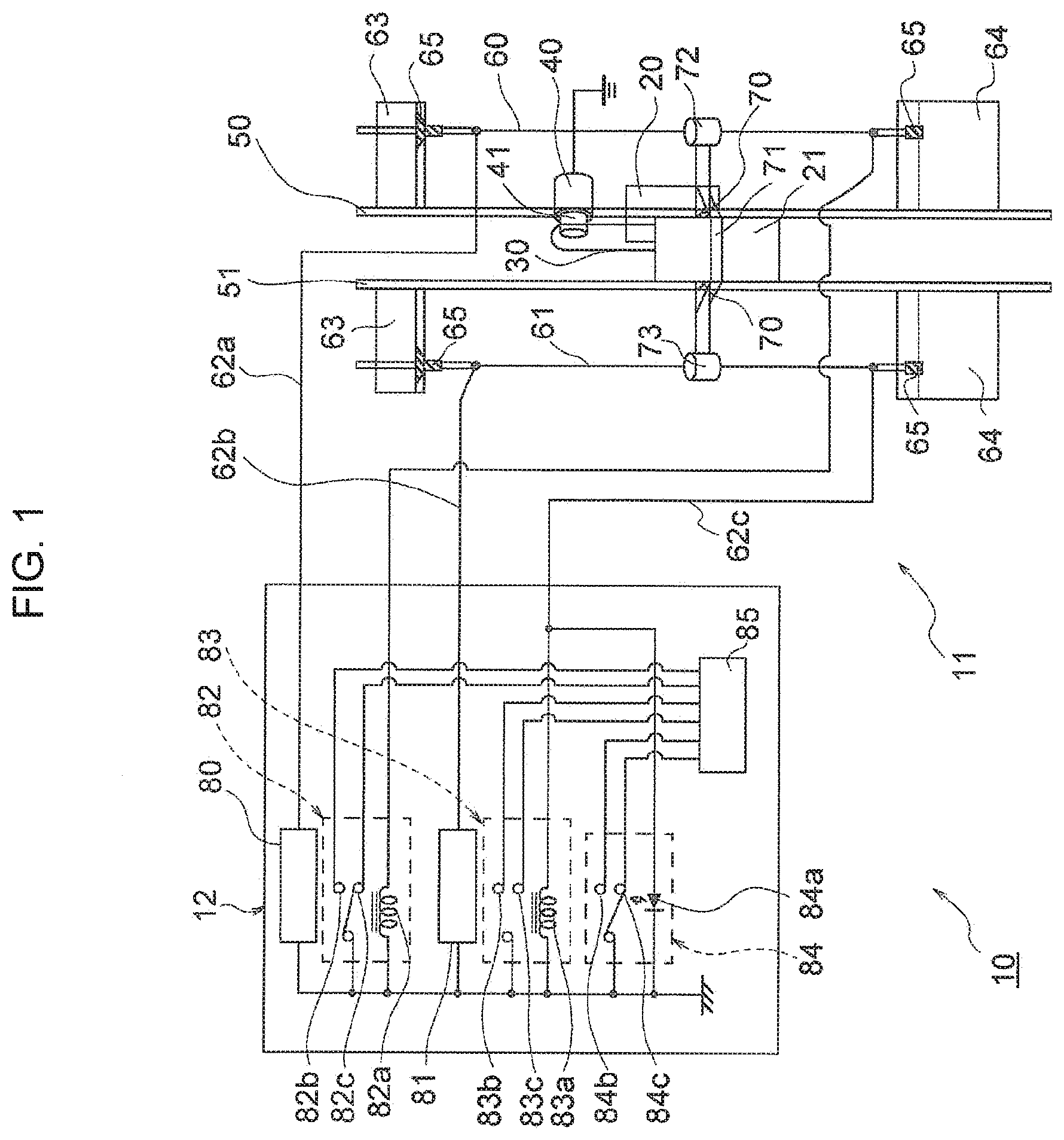
The present invention relates to a derailment detecting device for an elevator having an ascending and descending part guided on guide rails. In an elevator in general, ascending and descending bodies such as a cage and a counterweight are lifted and lowered as being guided on guide rails provided in the lifting and lowering direction. In an elevator derailment detecting device disclosed in PTL 1, a conductor wire through which weak current is passed is provided in the vicinity of and parallel to a guide rail. When the ascending and descending body is derailed from the guide rail, the contacting part provided at the ascending and descending body contacts the conductor wire and conducts electricity, the weak current passed through the conductor wire changes, and the current change is detected by a current detector connected to the conductor wire, so that the derailment of the ascending and descending body can be detected. [PTL 1] Japanese Patent Application Publication No. 2010-18423 However, when the elevator derailment detecting device disclosed in PTL 1 is provided in a building requiring a high lift height, each guide rail is prolonged for the entire elevator, which also prolongs the entire conductor wire, so that the conductor wire from the position of the ascending and descending body to the current detector is prolonged, and the electric resistance of the conductor wire to be detected increases. The electric resistance of the conductor wire may be instable if the conductor wire corrodes. This may make it difficult to detect change in weak current passed through the conductor wire. The present invention is directed to a solution to the foregoing problem, and it is an object of the present invention to provide an elevator derailment detecting device which can surely detect derailment of an ascending and descending body from a guide rail. In order to solve the problem, an elevator derailment detecting device according to the present invention includes an ascending and descending part, a guide rail which guides the ascending and descending part to be lifted and lowered, first and second conductor wires provided parallel to a direction in which the ascending and descending part is lifted and lowered, a contacting means as a conductor provided at the ascending and descending part and positioned near the first and second conductor wires, a first DC power supply unit which applies a first DC voltage to the first conductor wire, and a second DC power supply unit which applies a second DC voltage to the second conductor wire, and a different voltage detector which detects a voltage at the second conductor wire, the first and second DC voltages have different values, and the contacting means contacts the first and second guide wires when the ascending and descending part is derailed from the guide rail, so that a DC voltage generated at the second conductor wire is detected by the different voltage detector. The elevator derailment detecting device according to the present invention includes the first and second conductor wires provided parallel to the direction in which the ascending and descending part is lifted and lowered, the contacting means as a conductor provided at the ascending and descending part and positioned near the first and second conductor wires, the first DC power supply unit which applies the first DC voltage to the first conductor wire, and the second DC power supply unit which applies the second DC voltage to the second conductor wire, and the different voltage detector which detects a voltage at the second conductor wire, and the contacting means contacts the first and second guide wires when the ascending and descending part is derailed from the guide rail, so that a DC voltage generated at the second conductor wire is detected by the different voltage detector and therefore the derailment of the ascending and descending part can be surely detected. Now, an embodiment of the present invention will be described in conjunction with the accompanying drawings. The elevator system 10 includes a traction type elevator 11 and an elevator control board 12 having a device which controls the elevator 11. The elevator 11 includes a cage 20 and a counterweight 21 connected by a rope 30, the cage 20 can carry occupants, luggage, etc., and the counterweight 21 has a weight close to the weight of the cage 20 so that the weight counterbalances the cage 20. The rope 30 is placed around the driving part 41 of a hoisting machine 40, and the cage 20 and the counterweight 21 are suspended through the rope 30 in a substantially balanced state. The hoisting machine 40 includes a motor (not shown) as a motive power source for hoisting. When the rope 30 is hoisted by the hoisting machine 40, the counterweight 21 is raised and lowered as being guided on first and second guide rails 50 and 51, so that the cage 20 is raised and lowered as being guided on a guide rail (not shown). The counterweight 21 forms an ascending and descending part. A first conductor wire 60 is provided parallel to the first guide rail 50 in the lifting and lowering direction of the counterweight 21, and a second conductor wire 61 is provided parallel to the second guide rail 51. The first and second conductor wires 60 and 61 are attached, through conductor wire insulators 65, to upper end fixed parts 63 provided in the vicinity of the upper ends of the first and second guide rails 50 and 51 and lower end fixed parts 64 provided in the vicinity of the lower ends of the first and second guide rails 50 and 51. In this way, the first and second conductor wires 60 and 61 are provided linearly without slackness under prescribed tension. Note that the first and second conductor wires 60 and 61 are made of a highly conductive material with high corrosion resistance, while the first and second conductor wires 60 and 61 may be coated with a material with high corrosion resistance. Contacting means 71 is attached to the counterweight 21 through an insulator 70. The insulator 70 forms insulating means. The contacting means 71 is made of a carbon steel which is a highly conductive conductor. The contacting means 71 includes first and second contacting arms 72 and 73 at a prescribed distance. The first contacting arm 72 surrounds the first conductor wire 60, and the second contacting arm 73 surrounds the second conductor wire 61. More specifically, the first contacting arm 72 is provided in the vicinity of the first conductor wire 60, and the second contacting arm 73 is provided in the vicinity of the second conductor wire 61. Note that the contacting means 71 may be made of a material with high corrosion resistance other than the carbon steel or may be provided with a highly conductive coating with high corrosion resistance. The elevator control board 12 includes a first DC power supply device 80, a second DC power supply device 81, a first safety relay 82, a second safety relay 83, a contactless relay 84, and a relay detector 85. The first DC power supply device 80 is a constant voltage power supply device which outputs a DC voltage of 24 V in response to input of a DC voltage of 48 V from a DC power supply which is not shown and forms a first DC power supply unit. The second DC power supply device 81 is a constant voltage power supply device which outputs a DC voltage of 12 V in response to input of a DC voltage of 48 V from a DC power supply which is not shown and forms a second DC power supply unit. The first and second safety relays 82 and 83 are known contact relays generally called forced guided contact relays. The contactless relay 84 is a known contactless relay and advantageous in that the relay is less prone to a contact failure caused by corrosion. The contactless relay 84 is connected with an overcurrent circuit breaker (not shown) for detecting a short circuit attributable to a failure related to semiconductor therein. The first DC power supply device 80 has its output connected to the upper end of the first conductor wire 60 through a first electric wire 62 The second DC power supply device 81 has its output connected to the upper end of the second conductor wire 61 through a second electric wire 62 The second safety relay 83 includes a second NO contact 83 The second safety relay can open and close a contact when input voltage to the second coil 83 As shown in The first and second contacting arms 72 and 73 are provided so that the first cylindrical part 74 of the first contacting arm 72 contacts the first conductor wire 60 and the second cylindrical part 75 of the second contacting arm 73 contacts the second conductor wire 61 when the counterweight 21 is derailed from the first guide rail 50 or the second guide rail 51. The contacting means 71 is made of a carbon steel, and therefore when the counterweight 21 is derailed from the first guide rail 50 or the second guide rail 51, the first conductor wire 60 and the second conductor wire 61 are electrically connected with each other through the contacting means 71. Now, operation according to the embodiment of the present invention will be described with reference to As shown at A1 in A DC voltage of 24 V output by the first DC power supply device 80 is applied to the first coil 82 A DC voltage of 12 V output by the second DC power supply device 81 is applied to the second coil 83 Then, a DC voltage of 12 V output by the second DC power supply device 81 is applied to the input element 84 When the contactless relay NO contact 84 The first safety relay 82, the second safety relay 83, and the contactless relay 84 are in the states A2, A3, A4, and A5 in Now, operation carried out when the counterweight 21 is derailed from the first guide rail 50 or the second guide rail 51 (in the event of derailment) will be described (see B1 in As shown in The voltage drops Vd and Vd×2 are attributable to the resistance of the first conductor wire 60, the second conductor wire 61, the first electric wire 62 Here, when a voltage drop between the first conductor wire 60 and the second conductor wire 61 caused by the contacting means 71 is Vc, and the following expression (1) is satisfied, voltage from the first DC power supply voltage 80 is applied to the second conductor wire 61. When a voltage drop between the contacting means 71 and the contactless relay 84 is Ve, the operation voltage for the contactless relay 84 is Vr, and the following expression (2) is satisfied, input voltage to the input element 84 When the voltage drop Vc caused by the contacting means 71 is considered, the contacting means 71 made of a carbon steel has an electrical resistivity of 16.9 (μΩ·cm). Therefore, when the contacting means 71 has a length L (m) and a sectional area S (mm2), the resistance R of the contacting means 71 is obtained from the following expression (3). As shown in The voltage drop Ve is attributable to the resistance of the second conductor wire 61 and the third electric wire 62 Since the voltage drops Vd and Ve are sufficiently small and do not influence the opened and closed states of the first and second safety relays 82 and 83 as shown in Since the voltage drops Vc and Vd are sufficiently small, and the operation voltage Vr for the contactless relay 84 is more than a DC voltage of 12 V and at most a DC voltage of 24 V as an upper limit, the conditions defined by the expressions (1) and (2) are satisfied. Therefore, the contactless relay 84 operates to close the contactless relay NO contact 84 The relays each operate as described above, and the relay detector 85 detects the opened and closed state of each of the contacts at the first and second safety relays 82 and 83. It is determined that there is no circuit failure since the first NO contact 82 When it is determined that the counterweight 21 of the elevator 11 is in a derailed state (see B7 in Now, operation carried out when the counterweight 21 is not derailed from the first guide rail 50 or the second guide rail 51 but there is an abnormality caused in the circuit (in the event of a circuit abnormality) of the elevator system 10 will be described. When an abnormality occurs in the circuit of the elevator system 10 (see C1 in For example as shown in Then, when the safety device for the second DC power supply device 81 is activated and the output is stopped, no voltage is applied to the second coil 83 When the contactless relay 84 is short-circuited, the contactless relay NO contact 84 When the relay detector 85 determines the occurrence of a circuit failure, the relay detector 85 activates the stopper device (not shown) for the elevator 11 to shut down the elevator for emergency (see B8 in In this way, the device includes the counterweight 21, the first and second guide rails 50 and 51 which guide the counterweight 21 to be lifted and lowered, the first and second conductor wires 60 and 61 provided in parallel to the lifting and lowering direction of the counterweight 21, the contacting means 71 as a conductor provided at the counterweight 21 and positioned in the vicinity of the first and second conductor wires 60 and 61, the first DC power supply device 80 which applies a first DC voltage to the first conductor wire 60, a second DC power supply device 81 which applies a second DC voltage to the second conductor wire 61, and a contactless relay 84 which detects a voltage at the second conductor wire 61, the first DC voltage and the second DC voltage have different voltage values, and when the counterweight 21 is derailed from the first or second guide rail 50 or 51, the contacting means 71 contacts the first and second conductor wires 60 and 61, the contactless relay 84 therefore operates to detect a DC voltage generated at the second conductor wire 61, so that the derailment of the counterweight 21 from the first or second guide rail 50 or 51 can surely be detected. The contacting means 71 is provided at the counterweight 21 through the insulator 70 and has first and second contacting arms 72 and 73, and when the counterweight 21 is not derailed from the first or second guide rail 50 or 51, the first contacting arm 72 is in the vicinity of the first conductor wire 60 in a non-contact state, while the second contacting arm 73 is in the vicinity of the second conductor wire 61 in a non-contact state, so that the contacting means 71 can be lifted and lowered in the vicinity of the first and second conductor wires 60 and 61 in response to lifting and lowering of the counterweight 21. The first DC voltage has a higher value than the second DC voltage, and when the counterweight 21 is derailed from the first or second guide rail 50 or 51, the first contacting arm 72 contacts the first conductor wire 60 while the second contacting arm 73 contacts the second conductor wire 61, so that the first conductor wire 60 and the second conductor wire 61 are electrically connected with each other, the first DC voltage is applied to the second conductor wire 61, and therefore the contactless relay 84 can surely be operated to detect the derailment of the counterweight 21 from the first or second guide rail 50 or 51 on the basis of the voltage difference in DC voltage and the low resistance of the contacting means 71 as compared to the conventional elevator derailment detecting device in which there is no potential difference among multiple conductor wires. The contactless relay 84 is provided with the second DC voltage as an input when the counterweight 21 is not derailed from the first or second guide rail 50 or 51 and operated in response to input of a DC voltage higher than the second DC voltage when the counterweight 21 is derailed from the first or second guide rail 50 or 51, and therefore the derailment of the counterweight 21 from the first or second guide rail 50 or 51 can surely be detected as the relay detector 85 detects the operation state of the contactless relay 84 as compared to the method for directly detecting current change in the conductor wires as in the conventional elevator derailment detecting device. Since the first and second conductor wires 60 and 61 and the contacting means 71 are made of a corrosion resistant material or coated with a corrosion resistant material, the resistance thereof does not increase by corrosion. Since the device includes the first failure detector 82 which detects an abnormality at the first DC power supply device 80 or a circuit connected to the first conductor wire 60 and a second failure detector 83 which detects an abnormality at the second DC power supply device 81 or a circuit connected to the second conductor wire 61, not only the derailed state of the elevator 11 but also a failure at wiring in the elevator system 10 can be determined. Note that according to the embodiment, the first and second safety relays 82 and 83 are contact relays, while these relays may be contactless relays. In this case, connection with a means such as an overcurrent circuit breaker for detecting a short circuit caused by a failure in semiconductor inside and interrupting the circuit in order to prevent the circuit from becoming uninterruptible by a short-circuit in the contactless relay is required. A contact relay may be used instead of the contactless relay 84. In this case, a contact relay with high corrosion resistance is preferably used, weak current is constantly passed through an NC contact as a measure against a contact failure caused by generation of an organic substance at an NO contact attributable to a chloride or a sulfide, while the operation of the NO contact and the NC contact during operation are preferably monitored by the relay detector 85, etc. as a measure against a contact failure. The first DC power supply device outputs a DC voltage of 24 V, the second DC power supply device outputs a DC voltage of 12 V, the first safety relay 82 can operate when the input voltage to the first coil 82 The contacting means 71 is provided at the counterweight 21 while the elevator system may include the contacting means 71 provided at the cage 20 which forms the ascending and descending part and detect the derailment of the cage 20 from any of the guide rails. An elevator derailment detecting device according to the present invention detects the opened and closed states of contacts at first and second safety relays 82 and 83 (steps S1 and S2). Since a first NO contact 82b is closed, a first NC contact 82c is opened, a second NO contact 83b is closed, and a second NC contact 83c is opened, it is determined that there is no circuit failure. Then, the opened and closed state of the contactless relay 84 is detected (step S3). When the contactless relay NO contact 84b is closed and the contactless relay NC contact 84c is opened, it is determined that the counterweight 21 of the elevator 11 is in a derailed state. 1. An elevator derailment detecting device, comprising:
an ascending and descending part; a guide rail which guides the ascending and descending part to be lifted and lowered; first and second conductor wires disposed parallel to a direction in which the ascending and descending part is lifted and lowered; a contact as a conductor disposed at the ascending and descending part and positioned near the first and second conductor wires; a first DC power supply unit which applies a first DC voltage to the first conductor wire; and a second DC power supply unit which applies a second DC voltage to the second conductor wire; and a different voltage detector which detects a voltage at the second conductor wire, wherein the first and second DC voltages have different values, and the contact contacts the first and second guide wires when the ascending and descending part is derailed from the guide rail, so that a DC voltage is generated at the second conductor wire and detected by the different voltage detector. 2. The elevator derailment detecting device of when the ascending and descending part is not derailed from the guide rail, the first contacting arm is located near the first conductor wire in a non-contact state, while the second contacting arm is located near the second conductor wire in a non-contact state. 3. The elevator derailment detecting device of 4. The elevator derailment detecting device of the different voltage detector is configured to operate in response to input of the second DC voltage when the ascending and descending part is not derailed from the guide rail and in response to input of a higher DC voltage than the second DC voltage when the ascending and descending part is derailed from the guide rail. 5. The elevator derailment detecting device of 6. The elevator derailment detecting device of a first failure detector which detects an abnormality in the first DC power supply unit or the circuit connected to the first conductor wire, and a second failure detector which detects an abnormality in the second DC power supply unit or the circuit connected to the second conductor wire. 7. The elevator derailment detecting device of 8. The elevator derailment detecting device of 9. The elevator derailment detecting device of 10. The elevator derailment detecting device of a first failure detector which detects an abnormality in the first DC power supply unit or the circuit connected to the first conductor wire, and a second failure detector which detects an abnormality in the second DC power supply unit or the circuit connected to the second conductor wire. 11. The elevator derailment detecting device of a first failure detector which detects an abnormality in the first DC power supply unit or the circuit connected to the first conductor wire, and a second failure detector which detects an abnormality in the second DC power supply unit or the circuit connected to the second conductor wire. 12. The elevator derailment detecting device of a first failure detector which detects an abnormality in the first DC power supply unit or the circuit connected to the first conductor wire, and a second failure detector which detects an abnormality in the second DC power supply unit or the circuit connected to the second conductor wire. 13. The elevator derailment detecting device of a first failure detector which detects an abnormality in the first DC power supply unit or the circuit connected to the first conductor wire, and a second failure detector which detects an abnormality in the second DC power supply unit or the circuit connected to the second conductor wire. 14. The elevator derailment detecting device of a first failure detector which detects an abnormality in the first DC power supply unit or the circuit connected to the first conductor wire, and a second failure detector which detects an abnormality in the second DC power supply unit or the circuit connected to the second conductor wire. 15. The elevator derailment detecting device of a first failure detector which detects an abnormality in the first DC power supply unit or the circuit connected to the first conductor wire, and a second failure detector which detects an abnormality in the second DC power supply unit or the circuit connected to the second conductor wire. 16. The elevator derailment detecting device of a first failure detector which detects an abnormality in the first DC power supply unit or the circuit connected to the first conductor wire, and a second failure detector which detects an abnormality in the second DC power supply unit or the circuit connected to the second conductor wire.TECHNICAL FIELD
BACKGROUND ART
CITATION LIST
Patent Literature
SUMMARY OF INVENTION
Technical Problem
Solution to Problem
Advantageous Effects of Invention
BRIEF DESCRIPTION OF DRAWINGS
DESCRIPTION OF EMBODIMENTS
Embodiments
[Math. 1]
24−2×
[Math. 2]
24−2×
[Math. 3]REFERENCE SIGNS LIST