ERGONOMIC CUTTING TOOL
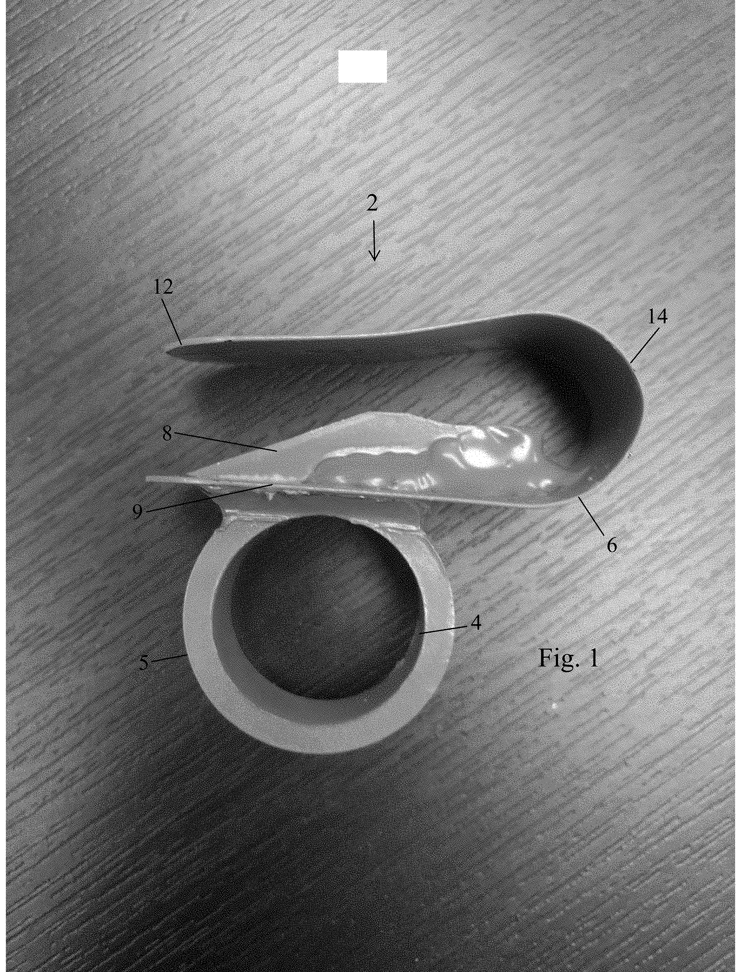
This application claims the benefit of U.S. Provisional Application No. 62/716,418, filed Aug. 9, 2018 the disclosure of which is incorporated by reference. The presently disclosed technology relates to an improved hand held cutting tool. More particularly, the present invention is a cutting tool for use in a variety of situation, including in gardening. A variety of cutting tools are known to assist a gardener in the garden. These cutting tools are used, for example, for cutting fruit off of vines, cutting fruit off of the plant, cutting flowers from their stems, and a variety of other purposes. However, many of the tools are awkward to use and are not comfortable to use. What is needed is a cutting tool that is ergonomic, easy to carry, and that provides a user with the ability to rotate the tool out of the user's palm and thus out of the user's way while working. What is further needed is a tool that utilizes a cutting blade to cut vines and stems but provides an inherent safety device to help avoid accidents in which a user's finger or other non-intended object is cut. While the presently disclosed inventive concept(s) is susceptible of various modifications and alternative constructions, certain illustrated embodiments thereof have been shown in the drawings and will be described below in detail. It should be understood, however, that there is no intention to limit the inventive concept(s) to the specific form disclosed, but, on the contrary, the presently disclosed and claimed inventive concept(s) is to cover all modifications, alternative constructions, and equivalents falling within the spirit and scope of the inventive concept(s) as defined herein. What is disclosed is a cutting tool 2 that has a base ring 4. The ring 4 is configured to fit on a user's finger. In a preferred embodiment the ring 4 can be a ring shaped device such as a broken ring to allow for the ring to expand to accommodate varying finger sizes. The ring has a circumference 5. Preferably the circumference ring has a cross section in an oval shape or a ror an interior domed fit similar to a comfort fit wedding ring to promote comfort of the user. The circumference of the ring defines a first plane 7. A cutting unit 6 is attached to the outer portion of the circumference of the ring. The cutting unit is attached such that the longitudinal axis 9 of the cutting unit is oriented in the same plane as the circumference of the ring 5. This provides an ergonomic cutting tool and facilitates ease of use. The ring is preferably constructed of a one piece molded plastic unit with a cutting edge affixed or formed on the interior of the ring. In a preferred embodiment the cutting unit 6 has a base section 9 and a top section 12. These correspond to a first arm of the U-shaped or V-shaped cutting unit and a second arm of the U-shaped or V-shaped cutting unit. The base section and top section are biased apart. In a preferred embodiment biasing is via a curved section 14 that operates as a biasing device or spring like function. A blade 8 is positioned between the lower section 9 and upper section 12 such that a user depressing upper section 12 pushes the upper section 12 toward the blade and thus any material between the upper section 12 and the blade 8 is forced onto the blade and cut. Alternatively used terminology herein is that the first arm and the second arm are biased together or toward one another, which includes depressing the first arm toward the second arm. The upper section in the depicted embodiment is a flat section configured for pushing material toward the blade. As shown, the cutting unit in a preferred embodiment has a generally U-shape; however the cutting unit can be provided in a V-shape or other shape congruent with the concepts disclosed herein. The flat section of the upper section or second arm is configured such that when compressed against the blade, the length of the cutting section of the blade is mated against the flat section, as shown in The device can be constructed using a variety of materials such as molded plastic or injected plastic, metal, or any other material that could be used. The ring can be a full ring as depicted or a half ring or three-quarter ring or other shape provided that the ring is able to be positioned on a user's finger. The ring can be open to accommodate varying finger sizes. Alternatively the ring can be manufactured in a variety of sizes to accommodate various user finger sizes. A variety of textures could be used on the upper member 58 to provide added friction between the user's thumb and the surface of the upper unit. This could include rubber or other material or texture. It is thought that providing the blade within the U-shape or V-shape of the cutting device will facilitate protection of the blade and of unintended foreign objects from encountering the blade. Still other features and advantages of the presently disclosed and claimed inventive concept(s) will become readily apparent to those skilled in this art from the description describing preferred embodiments of the inventive concept(s), simply by way of illustration of the best mode contemplated by carrying out the inventive concept(s). As will be realized, the inventive concept(s) is capable of modification in various obvious respects all without departing from the inventive concept(s). Accordingly, the drawings and description of the preferred embodiments are to be regarded as illustrative in nature, and not as restrictive in nature. What is disclosed is an improved cutting tool to provide improved cutting of small diameter materials, such as stems of flowers and other plants. The device provides a cutting mechanism that is parallel to or in the same plane of a circumference of a ring that is worn on the user's finger. This provides for an increased ergonomic cutting tool. The cutting tool has a blade and an opposing portion that is configured to retain the material to be cut while the blade is pressed into the material or the material can be pushed onto the blade. The device is preferably constructed of a unitary molded plastic with an integrated blade formed in the material. 1. a cutting device comprising:
a ring, said ring being configured to be positioned on a user's finger, said ring comprising a circumference, said circumference defining a plane; a cutting unit, wherein said cutting unit comprises an upper section and a lower section biased apart, wherein said upper section and said lower section define a length wherein said cutting unit is attached to said ring, wherein said cutting unit is attached to said ring such that said length of said cutting unit is oriented in the same plane as the circumference of said ring, wherein said upper section and said lower section are biased apart, wherein said cutting unit comprises a blade positioned between said upper unit and said lower unit and attached to one of said upper unit and said lower unit, wherein said blade extends along said length of said cutting unit, wherein said blade is attached to said lower section of said cutting unit, wherein said upper unit comprises a generally planar section free of a blade and configured such that when said upper section and said lower section are biased together to close said gap between said blade and said upper unit, a material to be cut is 2. The cutting device of 3. The cutting device of 4. The cutting device of 5. The cutting device of 6. The cutting device of 7. The cutting unit of 8. The cutting unit of 9. The cutting unit of 10. The cutting device of 11. A cutting device, said cutting device comprising:
A cutting unit, said cutting unit defining a generally u-shaped profile defining a valley and a first arm and a second arm, wherein said first arm and said second arm are biased apart; wherein said first arm and said second arm define a length extending from said valley, wherein said first arm comprises a cutting blade on an interior surface of said first arm, wherein said second arm comprises an inner surface configured to retain an item to be cut by said cutting blade when said first arm and said second arm are biased toward one another; a ring configured for wearing on a user's finger, wherein said cutting unit is attached to said ring on an outside of one of said arms of said U such that a length of said arms of said U are in a plane defined by a circumference of said ring, wherein a first arm comprises a cutting blade, wherein a second arm comprises a generally planar, wherein said first arm and said second arm are configured to be biased together when a user exerts force on an outer surface of one of said arms. 12. The cutting device of 13. The cutting device of 14. The cutting device of 15. The cutting device of 16. The cutting device of 17. The cutting unit of 18. The cutting unit of 19. The cutting unit of claim one, wherein said second arm is configured to bias toward said first arm when a user is 20. The cutting unit of PRIORITY/CROSS-REFERENCE TO RELATED APPLICATIONS
TECHNICAL FIELD
BACKGROUND
BRIEF DESCRIPTION OF THE DRAWINGS
DETAILED DESCRIPTION OF THE PREFERRED EMBODIMENTS