High-Pressure Fuel Pump
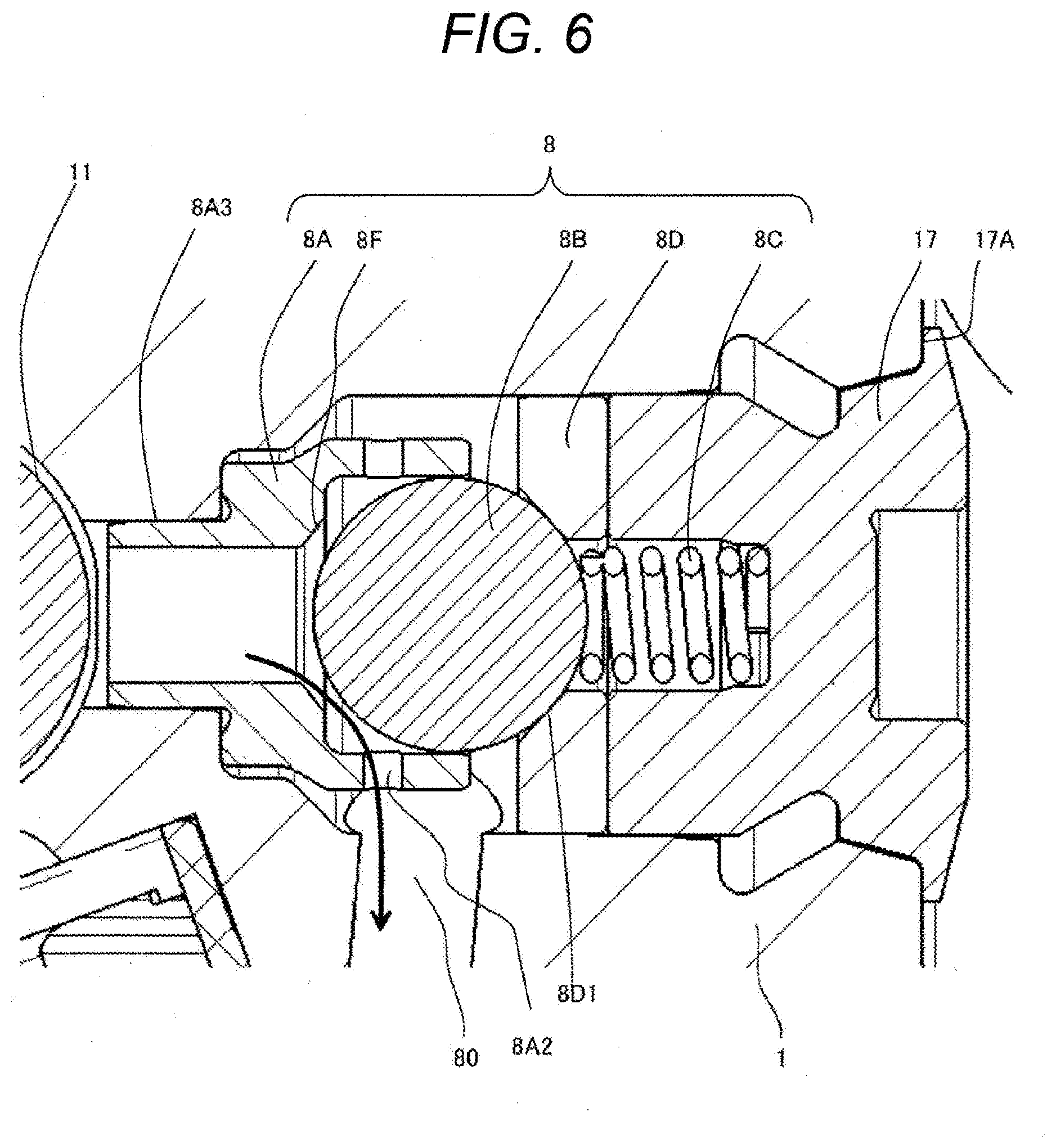
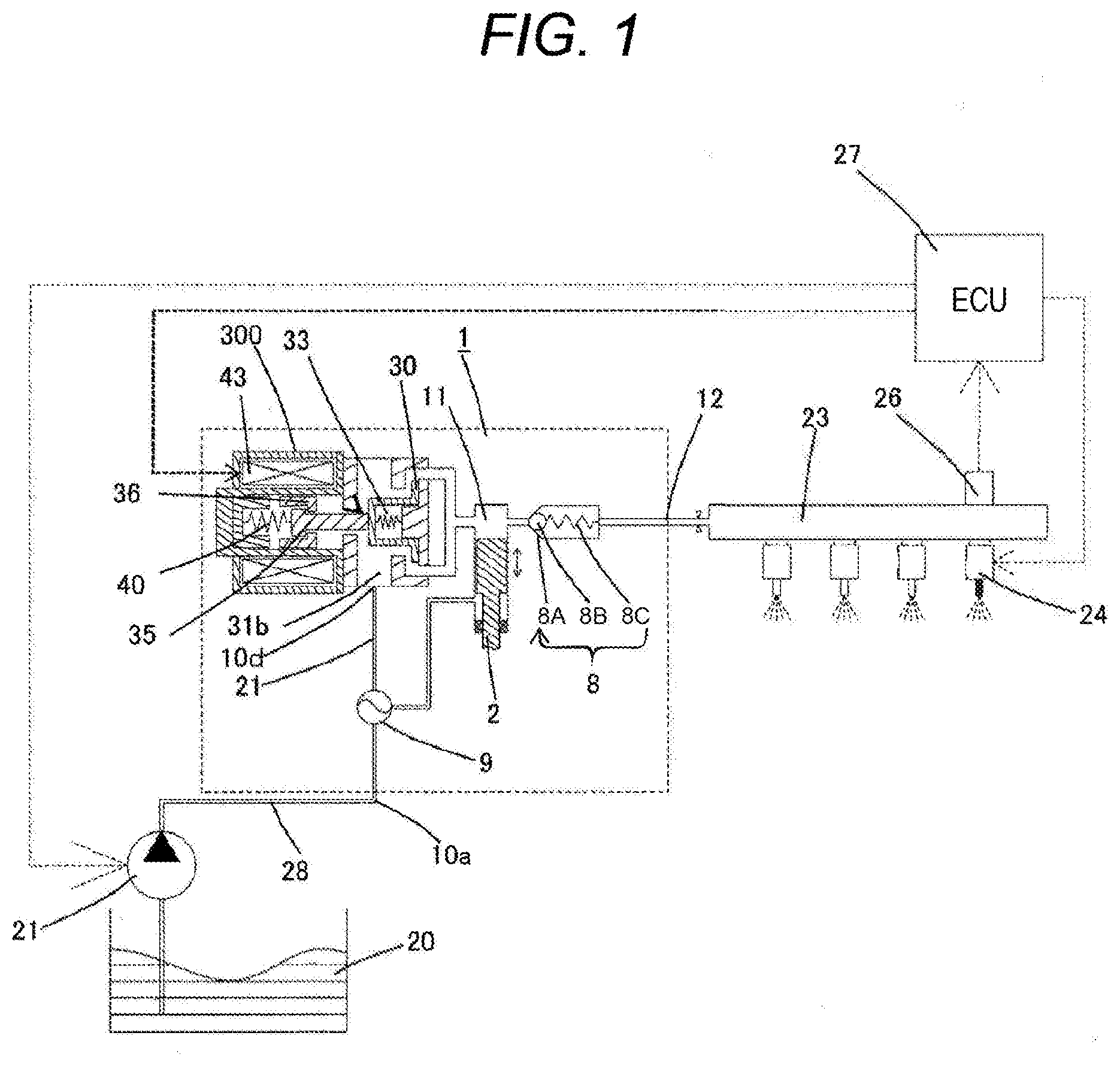
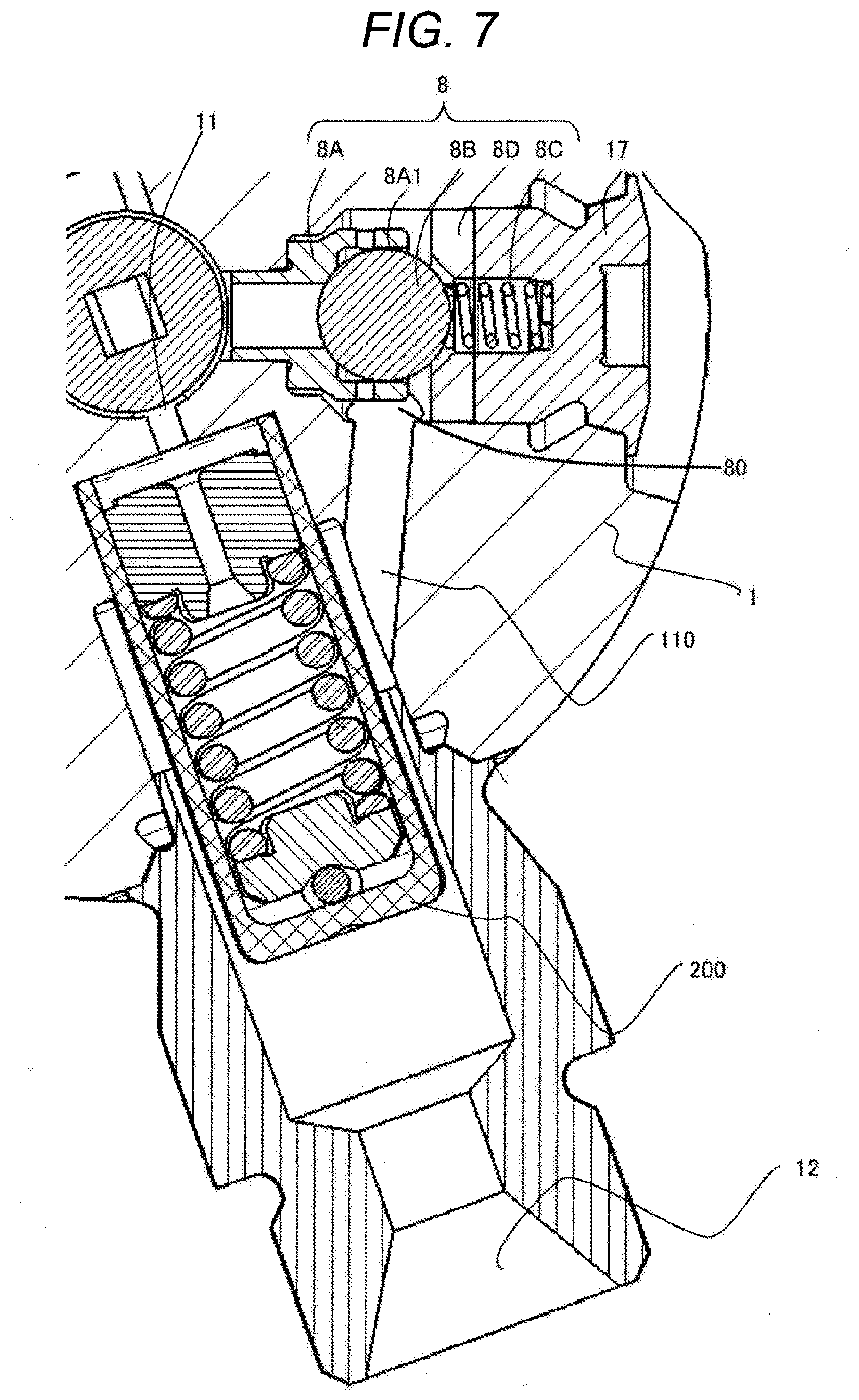
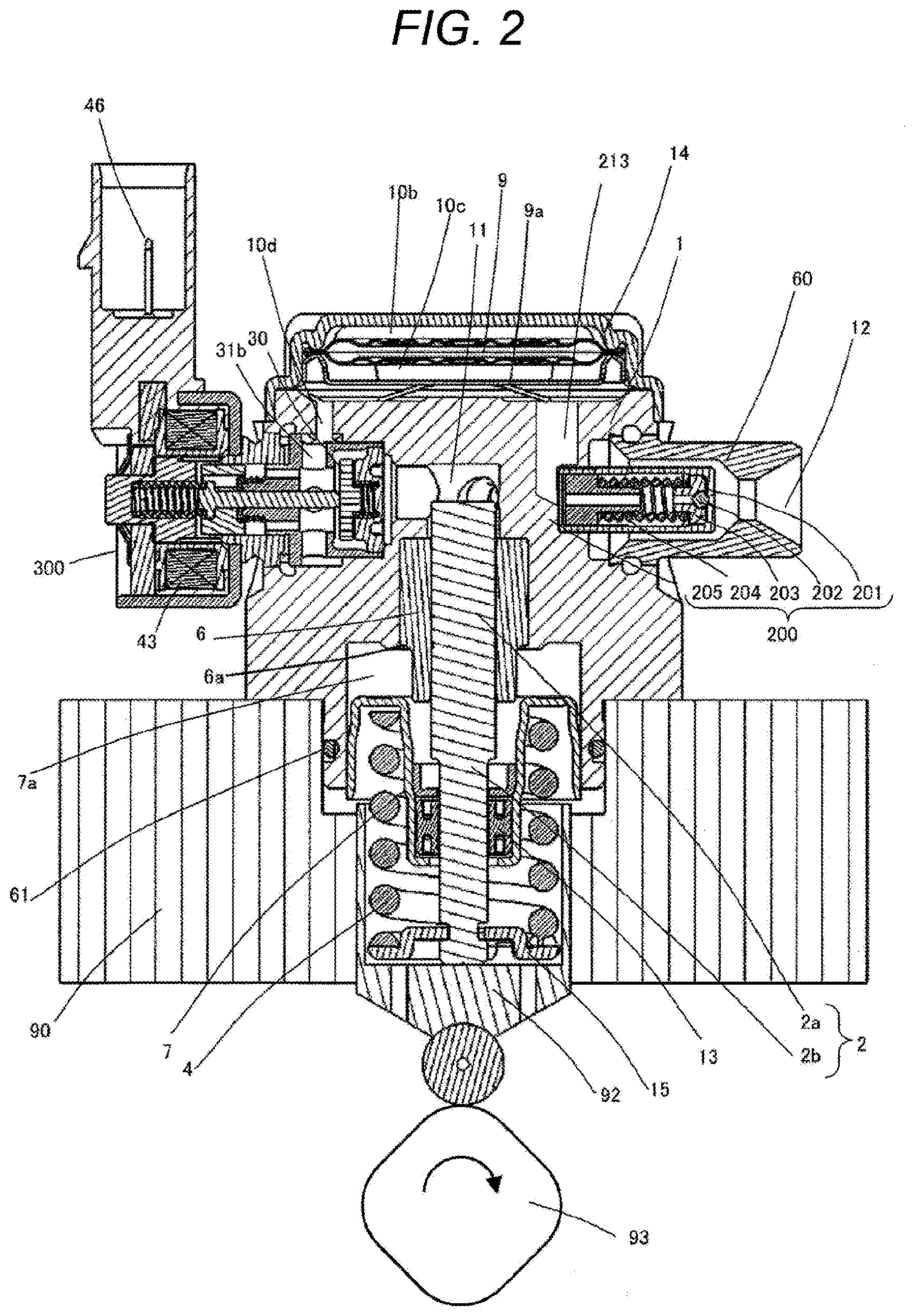
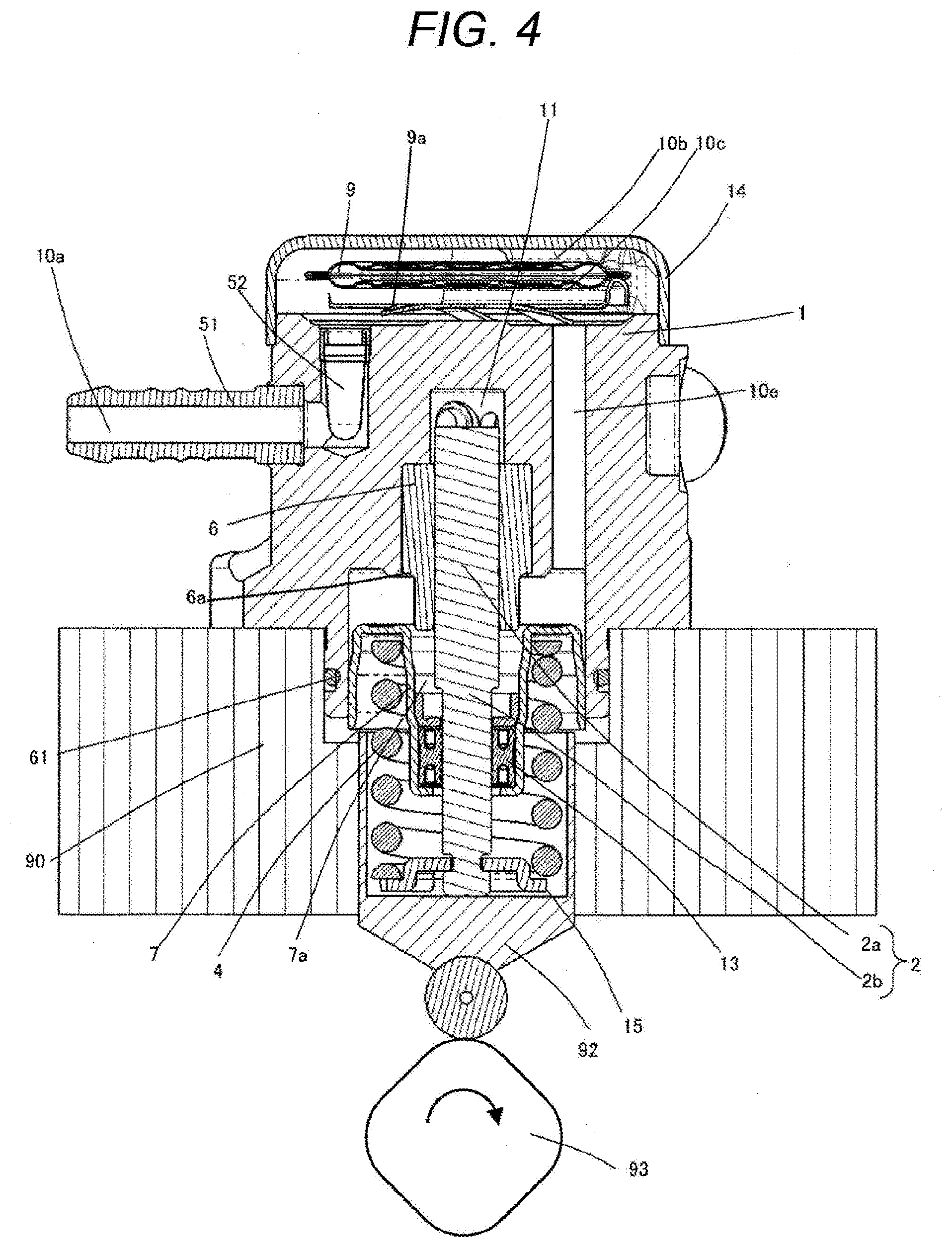
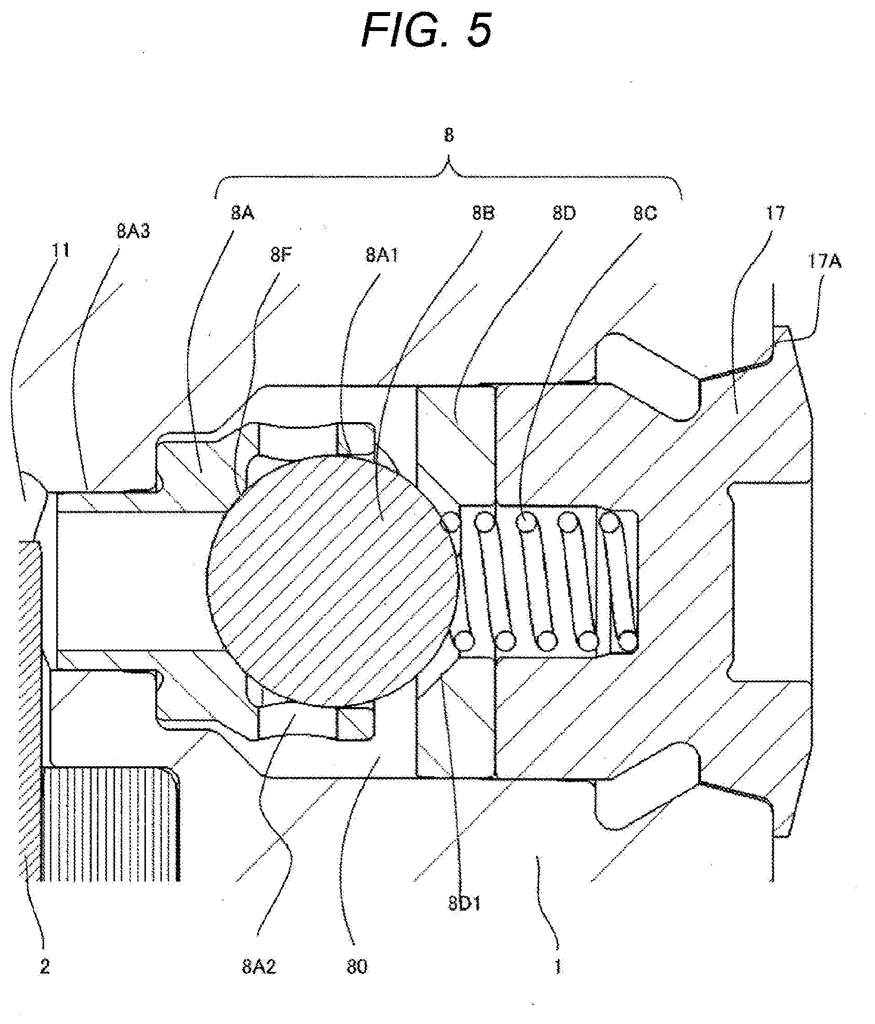
The present invention particularly relates to a discharge valve structure of a high-pressure fuel pump mainly applied to an internal combustion engine for automobiles. Plunger-type high-pressure fuel pumps for increasing the pressure of fuel are widely used in a direct-injection internal combustion engine for automobiles that inject fuel directly into a combustion chamber. As related art of a high-pressure fuel pump, Patent Literature 1 (JP 2011-80391 A) discloses a discharge valve unit that accommodates a valve body, a seat, and a spring. The discharge valve has a flat seat surface, and oil tightness can be obtained by polishing the abutment portion between the valve body and the seat with high accuracy. In Patent Literature 2 (WO 15/163246 A), there is one using a poppet valve. When the poppet valve receives back pressure and comes in abutment against a seat surface, the poppet valve makes hertz contact with a seat portion, so that oil tightness can be obtained. PTL 1: JP 2011-80391 A PTL 2: WO 15/163246 A However, in Patent Literature 1, since the discharge valve mechanism is a unit type, the space for attaching is large, and an increase in the overall size of the product is required for mounting. On the other hand, in Patent Literature 2, since it is not a unit type, the size of the product can be reduced. However, since the valve body is a poppet valve, the number of processing steps increases, and manufacture at a low cost is difficult. Accordingly, an object of the present invention is to provide a high-pressure fuel pump including a highly reliable discharge valve mechanism at low cost. In order to solve the above-mentioned problem, according to the present invention, there is provided a high-pressure fuel pump including: a discharge valve arranged on a discharge side of a pressurizing chamber; a discharge valve seat on which the discharge valve is seated; and a facing member configured independently as a separate member from the discharge valve seat and located on an opposite side of the discharge valve seat with the discharge valve interposed therebetween, in which a stroke direction regulating portion that regulates displacement of the discharge valve in a stroke direction is formed on a tapered surface of the facing member. According to the present invention, it is possible to provide a high-pressure fuel pump including a highly reliable discharge valve mechanism at low cost. The configurations, operations, and effects of the present invention other than those described above will be described in detail in the following embodiments. Hereinafter, embodiments of the present invention will be described below. The fuel in a fuel tank 20 is pumped up by a feed pump based on a signal from an engine control unit 27 (hereinafter referred to as ECU). This fuel is pressurized to an appropriate feed pressure and sent to a low-pressure fuel inlet port 10 The fuel that has passed through a suction joint 51 from the low-pressure fuel inlet port 10 The fuel that has flowed into the solenoid valve mechanism 300 passes through an inlet port that is opened and closed by the inlet valve 30 and flows into a pressurizing chamber 11. Reciprocating motion power is applied to a plunger 2 by a cam mechanism 93 of an engine. Through the reciprocating motion of the plunger 2, fuel from the inlet valve 30 is sucked during a downward stroke of the plunger 2 and the fuel is pressurized during an upward stroke. Via a discharge valve mechanism 8, the pressurized fuel is pumped to a common rail 23 on which a pressure sensor 26 is mounted. Based on a signal from an ECU 27, an injector 24 injects fuel into the engine. The present embodiment is a high-pressure fuel pump applied to a so-called direct injection engine system in which the injector 24 directly injects fuel into a cylinder tube of the engine. The high-pressure fuel pump discharges fuel at a flow rate of desired supply fuel by a signal from the ECU 27 to the solenoid valve mechanism 300. As shown in As illustrated in The cylinder 6 is press-fitted with the pump body 1 on the outer peripheral side thereof. The pump body 1 is formed with an insertion hole for inserting the cylinder 6 from below, and an inner peripheral convex portion is formed to be deformed to the inner peripheral side so as to come in contact with the lower surface of a fixed portion 6 At the lower end of the plunger 2, there is provided a tappet 92 that converts the rotational motion of the cam 93 attached to a camshaft of the internal combustion engine into vertical motion and transmits it to the plunger 2. The plunger 2 is pressure-bonded to the tappet 92 by a spring 4 through a retainer 15. Thereby, along with the rotational motion of the cam 93, the plunger 2 can be reciprocated up and down. A plunger seal 13 held at the lower end of the inner periphery of the seal holder 7 is installed in a slidable contact with the outer periphery of the plunger 2 at the lower part of the cylinder 6 in the figure. Thereby, when the plunger 2 slides, the fuel in a sub chamber 7 As shown in The fuel that has passed through the low-pressure fuel inlet port 10 The upper and lower surfaces of the pressure pulsation reduction mechanism 9 are formed with the low-pressure fuel inlet port 10 The fuel that has passed through the damper chambers (10 The suction port 31 The solenoid valve mechanism 300 will be described with reference to After the plunger 2 completes the suction stroke, the plunger 2 starts to move upward and moves to the upward stroke. Here, the electromagnetic coil 43 remains in a non-energized state and no magnetic biasing force acts. The rod biasing spring 40 biases a rod protrusion 35 In this state, when a control signal from the ECU 27 is applied to the solenoid valve mechanism 300, a current flows through the electromagnetic coil 43 via the terminal 46. A magnetic attraction force acts between a magnetic core 39 and an anchor 36, and the magnetic core 39 and the anchor 36 come in contact with each other at the magnetic attraction surface. The magnetic attraction force overcomes the biasing force of the rod biasing spring 40 and urges the anchor 36. The anchor 36 engages with the rod protrusion 35 At this time, the inlet valve 30 is closed by the biasing force of the inlet valve biasing spring 33 and the fluid force caused by the fuel flowing into the suction passage 10 That is, the upward stroke from the lower start point to the upper start point of the plunger 2 includes a return stroke and a discharge stroke. Then, by controlling the energization timing of the coil 43 of the solenoid valve mechanism 300, the amount of high-pressure fuel that is discharged can be controlled. The plunger 2 includes a large-diameter portion 2 As a result, such a function is provided that the flow rate of fuel into and out of the pump during the intake stroke or the return stroke of the pump can be reduced, and the pressure pulsation generated inside the high-pressure fuel pump is reduced. As shown in In a state where there is no fuel differential pressure between the pressurizing chamber 11 and a discharge valve chamber 12 When the fuel in the pressurizing chamber 11 is pressurized and the discharge valve 8 Next, a relief valve mechanism 200 shown in The relief valve mechanism 200 includes a relief body 201, a relief valve 202, a relief valve holder 203, a relief spring 204, and a spring stopper 205. The relief body 201 is provided with a tapered seat portion. The valve 202 is loaded with the load of the relief spring 204 via the valve holder 203 and is pressed against the seat portion of the relief body 201 to block the fuel in cooperation with the seat portion. When the pressure of the fuel outlet port 12 becomes abnormally high due to a failure of the solenoid intake valve 300 of the high-pressure fuel pump and becomes higher than the set pressure of the relief valve mechanism 200, the abnormal high-pressure fuel is discharged to the damper chamber 10 Hereinafter, the discharge valve mechanism 8 in the present embodiment will be described with reference to Therefore, the discharge valve mechanism 8 of the present embodiment will be described with reference to As shown in According to this configuration, since the stroke direction regulating portion 8D1 is formed on the tapered surface of the facing member 8D, the movement of the discharge valve 8B in the stroke direction can be stably regulated even if the discharge valve 8B is configured by an inexpensive ball valve. Accordingly, it is possible to configure a highly reliable discharge valve mechanism at low cost. In this embodiment, the discharge valve 8B is configured by a ball valve. According to this configuration, since the discharge valve 8B is configured by an inexpensive ball valve, it is possible to configure the discharge valve mechanism at low cost. In addition, according to this configuration, a high-pressure fuel pump that ensures oil tightness even at high fuel pressure and includes a small and lightweight discharge valve mechanism is provided. As shown in The discharge valve mechanism 8 includes the valve seat member 8A, the discharge valve 8B that opens and closes the discharge passage 81 by coming into abutment against or separating from the discharge valve seat 8F of the valve seat member 8A, and the discharge valve spring 8C that is attached to the plug member 17 (sealing plug) and urges the discharge valve 8B toward the discharge valve seat 8F. As described above, the stroke direction regulating portion 8D1 that regulates displacement of the discharge valve 8B in the stroke direction is formed on the tapered surface of the facing member 8D. In In this embodiment, the stroke regulating portion 8D is formed on the facing member 8D (plug member 17), but it may be formed on a discharge joint 150. That is, the high-pressure fuel pump of the present embodiment includes the discharge valve chamber 80 in which the discharge valve mechanism 8 including the discharge valve 8B and the discharge valve seat 8F is arranged, and the facing member 8D may be configured by the discharge joint 60 fixed to the pump body 1. The discharge valve 8B forms an annular contact surface 8F that can keep oil tightness by coming in contact with the discharge valve seat 8F of the discharge valve seat member 8A. Further, the discharge valve spring 8C is attached to the facing member 8D (plug member 17) and urges the discharge valve 8B toward the discharge valve seat 8F, that is, biases the discharge valve 8B in the valve closing direction. The discharge valve seat member 8A on which the discharge valve seat 8F is formed is formed with a radial direction regulating portion 8A1 that regulates displacement of the discharge valve 8B in the direction perpendicular to the stroke axis. According to this configuration, even when the discharge valve 8B is configured by an inexpensive ball valve, it is possible to regulate displacement of the discharge valve 8B in the direction perpendicular to the stroke axis. Accordingly, it is possible to configure a highly reliable discharge valve mechanism. It is desirable that the length of the discharge valve axial direction regulating portion 8A1 in the discharge valve axis direction is formed to be approximately half or more of the diameter of the discharge valve 8B. As a result, it is possible to stably regulate the displacement of the discharge valve 8B in the direction perpendicular to the stroke axis, and it is possible to configure a highly reliable discharge valve mechanism. Further, it is desirable that the length of the radial direction regulating portion 8A1 is larger than the length to the tapered surface of the sealing plug 17 (stroke of the discharge valve member 8B) in the discharge valve axial direction. As a result, it is possible to stably regulate the displacement of the discharge valve 8B in the direction perpendicular to the stroke axis, and it is possible to configure a highly reliable discharge valve mechanism. A radial direction flow path 8A2 that causes the fuel discharged via the ball valve 8B to flow toward the radially outer side of the discharge valve mechanism 8 is formed in the radial direction regulating portion 8A1 of the discharge valve seat member 8A on which the discharge valve seat 8F is formed. It is desirable that a plurality of radial direction flow paths 8A2 be formed on the outer periphery of the discharge valve seat. If the necessary flow path area of the radial direction flow path 8A2 can be ensured, the shape can be a circle, an ellipse, a long hole, a square, or the like. By forming the plurality of Radial direction flow paths 8A2 on the outer periphery of the discharge valve seat, a necessary flow path can be secured. Further, the high-pressure fuel pump of the present embodiment includes a press-fitting portion 8A3 in which the discharge valve seat member 8A on which the discharge valve seat 8F is formed is press-fitted into the pump body 1, and a welding portion 17A in which the facing member (sealing plug 17) is welded to the pump body 1, and the valve seat member 8A on which the discharge valve seat is formed and the facing member (sealing plug 17) are configured separately from each other in a non-contact manner. As shown in The high-pressure fuel pump of the present embodiment includes the relief valve mechanism 200 that returns fuel to the pressurizing chamber 11 or a low-pressure flow path such as a pressure pulsation reduction mechanism 9 or a suction passage 10 In the high-pressure fuel pump of the present embodiment, the fuel discharged through the discharge valve 8B flows on the radially outer side of the discharge valve mechanism 8 and through the flow path formed substantially horizontally in the pump body 1 configuring the pressurizing chamber 11, then flows through the relief valve chamber in which the relief valve mechanism 200 is arranged, and is discharged from the fuel outlet port 12. According to the present embodiment described above, the number of processing steps of the discharge valve 8B can be reduced, the valve body can be manufactured at low cost, and the high-pressure fuel pump itself can be realized without increasing the size. In addition, since the discharge valve 8B has a curved abutment portion, when a high back pressure is applied, the seat portion is slightly deformed by Hertz contact to form a sealing surface, and a high oil tightness can be exhibited. Therefore, a high-pressure fuel pump that ensures oil tightness even at high fuel pressure and has a small and lightweight discharge valve structure can be provided. Provided is a high-pressure fuel pump that ensures oil tightness even at high fuel pressure and has a small and lightweight inexpensive discharge valve structure. Therefore, a high-pressure fuel pump according to the present invention includes: a discharge valve arranged on a discharge side of a pressurizing chamber; a discharge valve seat on which the discharge valve is seated; and a facing member configured independently as a separate member from the discharge valve seat and located on an opposite side of the discharge valve seat with the discharge valve interposed therebetween, in which a stroke direction regulating portion that regulates displacement of the discharge valve in a stroke direction is formed on a tapered surface of the facing member. 1. A high-pressure fuel pump comprising:
a discharge valve arranged on a discharge side of a pressurizing chamber; a discharge valve seat on which the discharge valve is seated; and a facing member configured independently as a separate member from the discharge valve seat and located on an opposite side of the discharge valve seat with the discharge valve interposed therebetween, wherein a stroke direction regulating portion that regulates displacement of the discharge valve in a stroke direction is formed on a tapered surface of the facing member. 2. The high-pressure fuel pump according to 3. The high-pressure fuel pump according to wherein the facing member is configured by a plug member (plug) that shields the discharge valve chamber from outside. 4. The high-pressure fuel pump according to wherein the facing member is configured by a discharge joint fixed to a pump body. 5. The high-pressure fuel pump according to 6. The high-pressure fuel pump according to 7. The high-pressure fuel pump according to 8. The high-pressure fuel pump according to 9. The high-pressure fuel pump according to 10. The high-pressure fuel pump according to 11. The high-pressure fuel pump according to wherein the fuel discharged from the pressurizing chamber flows through a relief valve chamber, and then flows through a relief valve chamber in which the relief valve mechanism is arranged, and is discharged from a fuel outlet port. 12. The high-pressure fuel pump according to 13. The high-pressure fuel pump according to a press-fitting portion in which a discharge valve seat member on which the discharge valve seat is formed is press-fitted into the pump body; and a welding portion in which the facing member is welded to the pump body, wherein a discharge valve seat member on which the discharge valve seat is formed and the facing member are configured separately from each other in a non-contact manner.TECHNICAL FIELD
BACKGROUND ART
CITATION LIST
Patent Literature
SUMMARY OF INVENTION
Technical Problem
Solution to Problem
Advantageous Effects of Invention
BRIEF DESCRIPTION OF DRAWINGS
DESCRIPTION OF EMBODIMENTS
Example
REFERENCE SIGNS LIST