BEVELED COVERPLATE
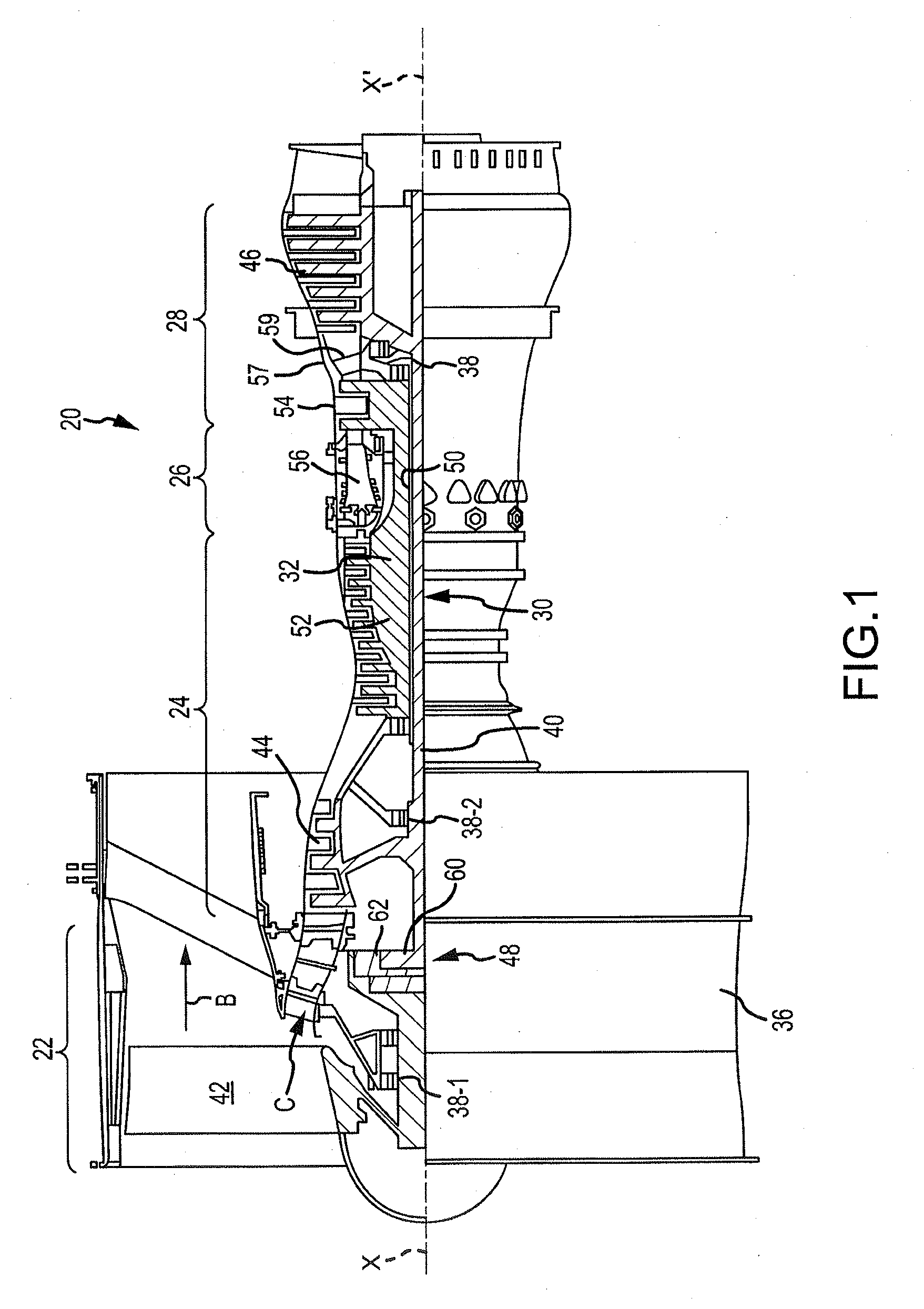
This application is a divisional of U.S. application Ser. No. 14/823,394, filed Aug. 11, 2015 for “BEVELED COVERPLATE”, which is a nonprovisional of, and claims priority to, and the benefit of U.S. Provisional Application No. 62/048,079, entitled “BEVELED COVERPLATE,” filed on Sep. 9, 2014, which is hereby incorporated by reference in its entirety. The present disclosure relates generally to a gas turbine engine and more specifically to turbine blades and/or vanes exposed to high temperature. A gas turbine engine may include a turbine section with multiple rows or stages of stator vanes and rotor blades that interact or react with a high temperature gas flow to create mechanical power. In a gas turbine engine, the turbine rotor blades drive the compressor and an electric generator to generate electrical power. The compressor can also include multiple rows or stages of stator vanes and rotor blades that compress air. The efficiency of the engine can be increased by passing a higher temperature gas flow through the turbine or by increasing the pressure ratio provided by the compressor. However, the turbine inlet temperature is limited to the vane and blade (airfoils) material properties and the cooling capabilities of these airfoils. The first stage airfoils are exposed to the highest temperature gas flow since these airfoils are located immediately downstream from the combustor. The temperature of the gas flow passing through the turbine progressively decreases as the rotor blade stages extract energy from the gas flow. Also, the pressure ratio is limited to the airfoil material properties and the cooling capabilities of these airfoils in the compressor. The increase in pressure and proximity to the combustor in later compressor stages causes the temperature within the combustor, and in particular on the airfoil surfaces, to increase. The foregoing features and elements may be combined in various combinations without exclusivity, unless expressly indicated otherwise. These features and elements as well as the operation thereof will become more apparent in light of the following description and the accompanying drawings. It should be understood, however, the following description and drawings are intended to be exemplary in nature and non-limiting. A gas turbine engine component is described. The gas turbine engine includes a platform that has a gas path side, a non-gas path side, a first mate face, and a second mate face. The second mate face has a beveled edge sloping towards the first mate face. The gas turbine engine also includes a coverplate that includes a first bend, a flat portion substantially parallel to the first mate face and a first wing substantially parallel to the second mate face. In various embodiments, the platform is an outer diameter platform. In various embodiments, the platform is an inner diameter platform. In various embodiments, the coverplate defines an impingement cooling hole. In various embodiments, the platform and the coverplate define a cavity. In various embodiments, the cavity includes an opening for at least one of channel flow cooling and axial flow cooling. In various embodiments, the first bend is between 10 degrees and 45 degrees. In various embodiments, the first bend is between 20 degrees and 30 degrees. In various embodiments, the gas turbine engine component also includes a cooling hole defined by the first wing. In various embodiments, the gas turbine engine component also includes a third mate face on the non-gas path side, the third mate face having a beveled edge partially facing the beveled edge of the second mate face, and the coverplate has a second bend and a second wing that partially faces the first wing with the second wing substantially parallel to the third mate face. In various embodiments, the second bend is bent at an angle and the first bend is bent at substantially a transverse of the angle. In various embodiments, the first wing defines a first cooling hole and the second wing defines a second cooling hole. In various embodiments, the platform and the coverplate define an opening to a core of the gas turbine engine component. In various embodiments, the gas turbine engine component also includes a leading edge and a trailing edge wherein the first bend extends substantially from the leading edge to the trailing edge. In various embodiments, the gas turbine engine component also includes an airfoil positioned on the gas path side of the platform. Also described is a gas turbine engine assembly. The assembly includes a compressor section, a combustor section and a turbine section. At least one of the compressor section or the turbine section includes a component that includes a platform. The platform includes a gas path side, a non-gas path side, and a platform floor on the non-gas path side. The platform also includes a first mate face on the non-gas path side that is offset from the platform floor by a first distance. The platform also includes a second mate face on the non-gas path side that includes a beveled edge sloping towards the platform floor. The second mate face is offset from the platform floor by a second distance that is larger than the first distance. The component also includes a coverplate that includes a first bend, a flat portion substantially parallel to the first mate face of the platform, and a first wing that is substantially parallel to the second mate face of the platform. In various embodiments, the assembly further includes a duct adapted to channel coolant from the compressor section to the non-gas path side of the platform. In various embodiments, the assembly also includes a cavity defined by the coverplate and the platform, wherein the coverplate defines a cooling hole adapted to allow coolant to flow into the cavity. Also described is a gas turbine engine component. The component includes a platform having a gas path side, and a non-gas path side. The platform also includes a first mate face, a second mate face having a beveled edge sloping towards the first mate face, and a third mate face adjacent the second mate face on the non-gas path side. The component also includes a coverplate that includes a first bend, a flat portion substantially parallel to the first mate face, and a first wing substantially parallel to the second mate face. The coverplate also includes a second bend and a second wing substantially parallel to the third mate face. The subject matter of the present disclosure is particularly pointed out and distinctly claimed in the concluding portion of the specification. A more complete understanding of the present disclosure, however, may best be obtained by referring to the detailed description and claims when considered in connection with the drawing figures, wherein like numerals denote like elements. The detailed description of exemplary embodiments herein makes reference to the accompanying drawings, which show exemplary embodiments by way of illustration and their best mode. While these exemplary embodiments are described in sufficient detail to enable those skilled in the art to practice the inventions, it should be understood that other embodiments may be realized and that logical, chemical and mechanical changes may be made without departing from the spirit and scope of the inventions. Thus, the detailed description herein is presented for purposes of illustration only and not limitation. For example, the steps recited in any of the method or process descriptions may be executed in any order and are not necessarily limited to the order presented. Furthermore, any reference to singular includes plural embodiments, and any reference to more than one component or step may include a singular embodiment or step. Also, any reference to attached, fixed, connected or the like may include permanent, removable, temporary, partial, full and/or any other possible attachment option. Additionally, any reference to without contact (or similar phrases) may also include reduced contact or minimal contact. As used herein, “aft” refers to the direction associated with the tail (e.g., the back end) of an aircraft, or generally, to the direction of exhaust of the gas turbine engine. As used herein, “forward” refers to the direction associated with the nose (e.g., the front end) of an aircraft, or generally, to the direction of flight or motion. In various embodiments and with reference to Gas turbine engine 20 may generally comprise a low speed spool 30 and a high speed spool 32 mounted for rotation about an engine central longitudinal axis X-X′ relative to an engine static structure 36 via several bearing systems 38, 38-1, and 38-2. It should be understood that various bearing systems 38 at various locations may alternatively or additionally be provided, including for example, bearing system 38, bearing system 38-1, and bearing system 38-2. Low speed spool 30 may generally comprise an inner shaft 40 that interconnects a fan 42, a low pressure (or first) compressor section 44 and a low pressure (or first) turbine section 46. Inner shaft 40 may be connected to fan 42 through a geared architecture 48 that can drive fan 42 at a lower speed than low speed spool 30. Geared architecture 48 may comprise a gear assembly 60 enclosed within a gear housing 62. Gear assembly 60 couples inner shaft 40 to a rotating fan structure. High speed spool 32 may comprise an outer shaft 50 that interconnects a high pressure (or second) compressor section 52 and high pressure (or second) turbine section 54. A combustor 56 may be located between high pressure compressor 52 and high pressure turbine 54. A mid-turbine frame 57 of engine static structure 36 may be located generally between high pressure turbine 54 and low pressure turbine 46. Mid-turbine frame 57 may support one or more bearing systems 38 in turbine section 28. Inner shaft 40 and outer shaft 50 may be concentric and rotate via bearing systems 38 about the engine central longitudinal axis X-X′, which is collinear with their longitudinal axes. As used herein, a “high pressure” compressor or turbine experiences a higher pressure than a corresponding “low pressure” compressor or turbine. The core airflow C may be compressed by low pressure compressor section 44 then high pressure compressor 52, mixed and burned with fuel in combustor 56, then expanded over high pressure turbine 54 and low pressure turbine 46. Mid-turbine frame 57 includes airfoils 59 which are in the core airflow path. Turbines 46, 54 rotationally drive the respective low speed spool 30 and high speed spool 32 in response to the expansion. Gas turbine engine 20 may be, for example, a high-bypass geared aircraft engine. In various embodiments, the bypass ratio of gas turbine engine 20 may be greater than about six (6). In various embodiments, the bypass ratio of gas turbine engine 20 may be greater than ten (10). In various embodiments, geared architecture 48 may be an epicyclic gear train, such as a star gear system (sun gear in meshing engagement with a plurality of star gears supported by a carrier and in meshing engagement with a ring gear) or other gear system. Gear architecture 48 may have a gear reduction ratio of greater than about 2.3 and low pressure turbine 46 may have a pressure ratio that is greater than about 5. In various embodiments, the bypass ratio of gas turbine engine 20 is greater than about ten (10:1). In various embodiments, the diameter of fan 42 may be significantly larger than that of the low pressure compressor section 44, and the low pressure turbine 46 may have a pressure ratio that is greater than about 5:1. Low pressure turbine 46 pressure ratio may be measured prior to inlet of low pressure turbine 46 as related to the pressure at the outlet of low pressure turbine 46 prior to an exhaust nozzle. It should be understood, however, that the above parameters are exemplary of various embodiments of a suitable geared architecture engine and that the present disclosure contemplates other turbine engines including direct drive turbofans. As illustrated, platform 104 is an outer diameter platform and platform 105 is an inner diameter platform. Aspects discussed herein can apply to an inner diameter platform as well as an outer diameter platform. Platform 104 includes a leading edge rail 108 and a trailing edge rail 109. As shown in Platform 104 and/or coverplate 106 may be made from, for example, metal, for example, stainless steel, an austenitic nickel-chromium-based alloy such as Inconel® which is available from Special Metals Corporation of New Hartford, N.Y., USA, titanium, composite materials, and other suitable materials or the like. They may be manufactured using a process drip method, metal laser sintering, casting, an additive manufacturing process, stamping sheet metal and/or the like. Mate face 202 Coverplate 106 includes wing 204 Wing 204 Between wing 204 As each bend 206 To account for manufacturing tolerances, for example, bend 206 The angle of bends 206 can be selected at least partially based on material properties. Bends 206 are preferably kept at an angle consistent with allowing flush interface between coverplate 106 and mate faces 202, thus minimizing losses to heat transfer caused by escape of cool air through gaps which would otherwise form therebetween. Cooling holes 107 may be provided in coverplate 106. In various embodiments, cooling holes 107 In various embodiments, platform 104 may require most cooling near mate faces 202 Platform 104 includes platform floor 209. Between coverplate 106 and platform floor 209 are cooling cavity 208 Because coverplate 106 is relatively close to platform 104, cooling cavities 208 may have relatively short distances (e.g., distances 210, 212) between coverplate 106 and platform 104. Smaller distances 210, 212 are preferable, because shallower cooling cavities 208 result in better cooling. Angles of bends 206 can be chosen based on balancing of optimal cooling cavity 208 distances 210, 212 and structural properties of coverplate 106. Cooling hole 107 Embodiments of component 100 utilizing bends 206 on coverplate 106 and/or beveled mate face 202 If coverplate 106 were to be flat (i.e., not including bends 206), mate face 202 In order to accommodate secondary wing 204 The embodiment of component 100 illustrated in Various benefits and other advantages have been described herein with regard to specific embodiments. Furthermore, the connecting lines shown in the various figures contained herein are intended to represent exemplary functional relationships and/or physical couplings between the various elements. It should be noted that many alternative or additional functional relationships or physical connections may be present in a practical system. However, the benefits and advantages, and any elements that may cause any benefit or advantage to occur or become more pronounced are not to be construed as critical, required, or essential features or elements of the disclosure. Reference to an element in the singular is not intended to mean “one and only one” unless explicitly so stated, but rather “one or more.” Moreover, where a phrase similar to “at least one of A, B, or C” is used in the claims, it is intended that the phrase be interpreted to mean that A alone may be present in an embodiment, B alone may be present in an embodiment, C alone may be present in an embodiment, or that any combination of the elements A, B and C may be present in a single embodiment; for example, A and B, A and C, B and C, or A and B and C. Different cross-hatching is used throughout the figures to denote different parts but not necessarily to denote the same or different materials. Systems, methods and apparatuses are provided herein. In the detailed description herein, references to “one embodiment”, “an embodiment”, “various embodiments”, etc., indicate that the embodiment described may include a particular feature, structure, or characteristic, but every embodiment may not necessarily include the particular feature, structure, or characteristic. Moreover, such phrases are not necessarily referring to the same embodiment. Further, when a particular feature, structure, or characteristic is described in connection with an embodiment, it is submitted that it is within the knowledge of one skilled in the art to affect such feature, structure, or characteristic in connection with other embodiments whether or not explicitly described. After reading the description, it will be apparent to one skilled in the relevant art(s) how to implement the disclosure in alternative embodiments. Furthermore, no element, component, or method step in the present disclosure is intended to be dedicated to the public regardless of whether the element, component, or method step is explicitly recited in the claims. No claim element herein is to be construed under the provisions of 35 U.S.C. 112(f), unless the element is expressly recited using the phrase “means for.” As used herein, the terms “comprises”, “comprising”, or any other variation thereof, are intended to cover a non-exclusive inclusion, such that a process, method, article, or apparatus that comprises a list of elements does not include only those elements but may include other elements not expressly listed or inherent to such process, method, article, or apparatus. A gas turbine engine includes a platform that has a gas path side, a non-gas path side, a first mate face, and a second mate face. The second mate face has a beveled edge sloping towards the first mate face. The gas turbine engine also includes a coverplate that includes a first bend, a flat portion substantially parallel to the first mate face and a first wing substantially parallel to the second mate face. 1. A gas turbine engine assembly, comprising:
a compressor section; a combustor section; and a turbine section, wherein at least one of the compressor section or the turbine section includes a component that includes:
a platform having:
a gas path side, a non-gas path side, a platform floor on the non-gas path side, a first mate face on the non-gas path side offset from the platform floor by a first distance,
a second mate face on the non-gas path side, the second mate face having a beveled edge sloping towards the platform floor and offset from the platform floor by a second distance that is larger than the first distance, and a coverplate including a first bend, a flat portion substantially parallel to the first mate face of the platform, and a first wing that is substantially parallel to the second mate face of the platform. 2. The assembly of 3. The assembly of 4. A gas turbine engine assembly, comprising:
a compressor section; a combustor section; and a turbine section, wherein at least one of the compressor section or the turbine section includes a component that includes:
a platform having:
a gas path side, a non-gas path side, a platform floor on the non-gas path side, a first mate face on the non-gas path side offset from the platform floor by a first distance,
a second mate face on the non-gas path side, the second mate face having a beveled edge sloping towards the platform floor and offset from the platform floor by a second distance that is larger than the first distance, and a coverplate including a first bend, a flat portion substantially parallel to the first mate face of the platform, and a first wing that is substantially parallel to the second mate face of the platform, wherein the platform is an inner diameter platform.CROSS-REFERENCE TO RELATED APPLICATIONS
FIELD
BACKGROUND
SUMMARY
BRIEF DESCRIPTION OF THE DRAWINGS
DETAILED DESCRIPTION