METHOD AND APPARATUS FOR IDENTIFYING A FORCE EXERTED BY A PART THAT CAN BE ELECTRICALLY ADJUSTED BY WAY OF AN ELECTRIC MOTOR ON A BODY THAT MAY BE RESTING ON SAID PART (AS AMENDED)
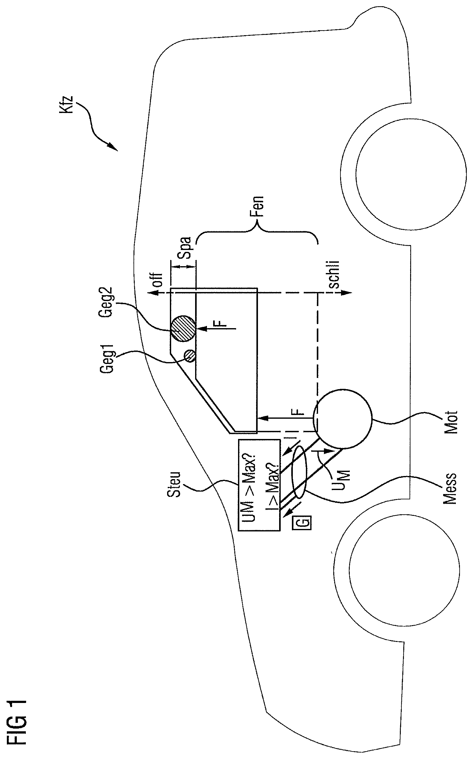
This application is the U.S. National Phase Application of PCT International Application No. PCT/EP2017/065893, filed Jun. 27, 2017, which claims priority to German Patent Application No. 10 2016 212 046.8, filed Jul. 1, 2016, the contents of such applications being incorporated by reference herein. The invention relates to a method and an apparatus for identifying a force exerted by a part (in particular a seat or closing part, such as, in particular, a window winding system or a sunroof or a trunk lid or a sliding door of a motor vehicle) that can be electrically adjusted by way of an electric motor on a body that may be resting on said part. DE 10 2009 008 369 A1, DE 10 2009 035 449 B3 and DE 10 2005 000753 A1, which are incorporated by reference, each describe methods for identifying jamming of a moved closing part. An aspect of the invention aims to optimize identification of a force on a part, such as, in particular, a closing part or a seat. As alternatives to present solutions, refinements of aspects of the invention can make it possible to identify a force on a part such as, in particular, a closing part or a seat, effectively in an alternative manner. Refinements of aspects of the invention solve the problem of the identification of the force acting on a movable part, in particular a closing part or seat, when the part is stationary (or virtually stationary). The part is operated here, for example, by way of a DC motor. With respect to some configurations of aspects of the invention: according to refinements of aspects of the invention, in particular for pretension of the moved part (in particular closing part or seat) and/or of the motor, a voltage whose magnitude is below a prescribed motor voltage threshold value (before a variable representing the movement of the motor, such as, for example, a voltage or a current or an angle encoder value, is measured or calculated or estimated, for example, by way of the measurement device during freewheeling of the motor) is applied to the motor, in particular a voltage whose magnitude is below a prescribed motor voltage threshold value that would be necessary in order to cause the part to move. According to refinements of aspects of the invention, the actuation system can be, for example, a reliable full-bridge having electronically actuatable switching elements such as, for example, field-effect transistors, which full-bridge is configured to switch the motor switched thereby to freewheeling and/or high impedance and/or for exerting a force (driving in the opposite direction and/or in the direction of a body) on the part. According to refinements of aspects of the invention, the actuation system can also use, for example, a pulse-width-modulation device, in order to switch the motor switched thereby to freewheeling and/or high impedance and/or to a lower voltage or to a voltage for movement/rotational movement of the part in a direction different to that executed most recently. Further features and advantages of some advantageous refinements of aspects of the invention will emerge from the following description of some exemplary embodiments of the invention with reference to the drawing, in which, to illustrate some possible refinements of the invention, in a schematically simplifying manner: Jamming of the closing part Fen (for example by an object (subsequently also called body) Geg1 or Geg2, such as, for example, a sausage or a hand in the free gap Spa above the closing part Fen) is detected by way of an actuation system Steu of a motor Mot, in particular when the motor is stationary, by means of (for example the average value and/or maximum and/or profile etc. of) a variable G (for example a voltage UM at the motor Mot) measured by way of a measurement device Mess, whereupon, for example, the direction of movement (schlie) of the closing part Fen could be delayed, stopped or inverted (off). In In Determination of the external force when the closing part Fen is (at least virtually) stationary is currently not used in the at least internally known prior art. Current, at least internally known force limitation/torque limitation/jamming protection systems make a reversing decision during operation, that is to say before the closing part Fen is stationary. Due to this premature decision, some of the robustness with respect to faulty reversal could be lost, since the tripping threshold would be adjusted based on the closing speed or the gradient of the speed. If the movable closing part Fen is successively braked to a stationary state, the robustness can advantageously be increased. Exemplary embodiments of the invention describe alternative methods for determining the external force (on a motor Mot) by a resting object Geg1 or Geg2. According to one refinement of the invention, in particular, a FET full-bridge having transistors T1, T2, T3, T4 is possible as the motor actuation system Steu (but it would also be possible to use a relay actuation system, for example). During the normal operating procedure, the motor Mot is actuated, for example, by means of the control system Steu using, for example, FETs T1-T4 in the desired direction of movement off/schli and is short-circuited at the end of the movement (for example when the window is closed etc.) for an improved braking action. One idea of a refinement of the invention is to carry out force identification (for example clamping force identification) when the motor Mot is (virtually stationary, for example with less than 0.1% or 1% of its maximum speed upon closing, or) stationary. This can be carried out using the following procedure:
To this end, the motor movement equation is: wherein J is the mass moment of inertia, ML is the load torque and MA is the armature torque (which results from the Lorentz force as follows: ML=c1ΦIA). The current IAis, for example, zero in accordance with an electrical decay process. This results in the equation J dω/dt=ML. The load torque ML can then be inferred from the profile of the angular velocity ω. The electrical motor equation UM=c2Φω in this motor state shows that the motor voltage UMis proportional to the angular velocity w of the motor Mot. The motor voltage UMcan be measured and evaluated. When the closing part Fen is loaded by an external force (case of clamping, for example by an object Geg1 or Geg2), the profile of the voltage UMduring the relaxing process is, for example, steeper and the maximum value is, for example, higher than in the case of low loading. For example, the voltage (or the current) can be averaged over a period (for example of 20 ms) and the averaged voltage can be used as the correlated variable with respect to the external force. If the averaged voltage (or the averaged current) reaches a, for example empirically determined, threshold value, which is dependent on the system (mechanics, drive, motor), a case of jamming is identified. A further option provides clocking between the short-circuited motor Mot and high impedance. It is possible to use a determined, previously set duty cycle and to ascertain whether a return to this operating state takes place or not. Some possible advantages: by estimating the closing force and/or angular velocity w when the motor Mot is stationary, essentially the following advantages can be produced, in particular, when used in jamming protection methods:
Instead of by means of the voltage, the movement and/or angular velocity of the motor could also be measured, for example, by way of an angle encoder and/or Hall sensor, or a current I through the motor could also be measured. Also, without generating freewheeling, a voltage (back-emf) that is low (that is to say, for example, lower than that required/used for the opening/closing/adjusting movement of the part) can be applied (for example 1 V) and/or a current I through the motor Mot could also be used as measurement variable (which can also represent the voltage, for example) and/or additionally the monitoring duration could be shortened (for example T<20 ms). for example, up to the time t31, the motor Mot is operated by way of pulse width modulation PWM, for example by way of a supply voltage of 12 V and a duty cycle of 24%; the motor Mot is located here in a stationary state (blocked). The motor Mot is then operated at high impedance. The relaxing process can be observed by the motor voltage measurement (for example measurement of a generator voltage UMas variable G to be measured). In this case, without the case of jamming, the maximum generator voltage is Delta-U=706.25 mV after t32=18.4 ms. up to the time t41, the motor Mot is operated and/or driven, for example, by way of PWM (for example by way of a supply voltage of 12 V and a duty cycle of 24%). The motor Mot is located here in a stationary state (blocked). The motor Mot is then operated at high impedance from t41, for example. A relaxing process can be observed by a motor voltage measurement (for example of a generator voltage UMas variable G to be measured). The maximum generator voltage UM(from the motor Mot) in a case of jamming is in this case, for example, Delta-U=981.25 mV after t42=14.5 ms. The force F is identified, for example, while a voltage UMis applied to the motor Mot when the motor Mot is, for example, stationary or virtually stationary, which voltage UMis, for example, lower than a prescribed limit value and/or which voltage is intended to effect a force F of the part Stz lower than a prescribed limit value on the body Geg3 and/or is low enough to not yet trigger any (significant) movement of the body Geg3, and/or which voltage UMis oriented so that, if it were greater, it would effect a movement in a direction opposite to the last movement of the object Geg3. Based, for example, on a measured voltage UMat the motor Mot and/or a current I through the motor Mot and/or an angle encoder value, for example, the magnitude of a force F of the part Stz on a body Geg3 (and/or a torque Dr in the motor) can be identified and, for example, compared with a limit value Max (and, upon exceedance of a limit value Max, the motor Mot can be reversed where necessary, for example). An exerted force F or an exerted torque Dr can generally be identified by a part on a body, for example, in such a way that it is identified whether a measurable force F or an exerted torque is exerted and/or whether a force F or an exerted torque Dr lower than, for example, a stored limit value Max is exerted. A method and an apparatus for identifying a force and/or torque exerted by a part, in particular a seat or closing part , such as, a window winding system or sunroof or trunk lid or sliding door of a motor vehicle, that can be electrically adjusted by way of an electric motor on a body resting on said part, having an actuation system, which is configured to apply a voltage to the motor, which voltage causes a force of the part on a body, if present, resting on the part, having a measurement device, which is configured, while the motor is stationary, to measure a variable of the motor representing a movement of the motor, having a comparison device, which is configured to identify, based on the measured variable, a force that is exerted by the part on a body resting on the part. 1. An apparatus for identifying a force exerted by
a seat or closing part, selected from the group consisting of a window winding system, a sunroof, a trunk lid, and a sliding door of a motor vehicle, that can be electrically adjusted by way of an electric motor on a body resting on said part, the apparatus comprising: an actuation system, which is configured to apply a voltage to the motor, which voltage causes the force of the part on the body, if present, resting on said part, a measurement device, which is configured, while the motor is stationary, to measure a variable of the motor representing a movement of the motor, and a comparison device, which is configured to identify, based on the measured variable, the force exerted by the part on the body resting on said part. 2. The apparatus as claimed in 3. The apparatus as claimed in 4. The apparatus as claimed in 5. The apparatus as claimed in 6. The apparatus as claimed in 7. The apparatus as claimed in 8. The apparatus as claimed in 9. The apparatus as claimed in 10. The apparatus as claimed in 11. The apparatus as claimed in 12. The apparatus as claimed in 13. The apparatus as claimed in 14. The apparatus as claimed in 15. The apparatus as claimed in 16. The apparatus as claimed in 17. The apparatus as claimed in 18. The apparatus as claimed in 19. The apparatus as claimed in 20. A method for identifying a force and/or a torque of a closing part or a seat of a motor vehicle that can be moved by way of an electric motor of the motor vehicle, on a body, wherein when the motor is substantially stationary and/or after the application of a voltage to the motor a variable representing a movement of the motor by way of a relaxation of a body resting on the part is measured, wherein the force and/or torque is identified based on the measured variable.CROSS REFERENCE TO RELATED APPLICATIONS
FIELD OF THE INVENTION
BACKGROUND OF THE INVENTION
SUMMARY OF THE INVENTION
BRIEF DESCRIPTION OF THE DRAWINGS
DETAILED DESCRIPTION OF THE PREFERRED EMBODIMENTS