TABLE SAW
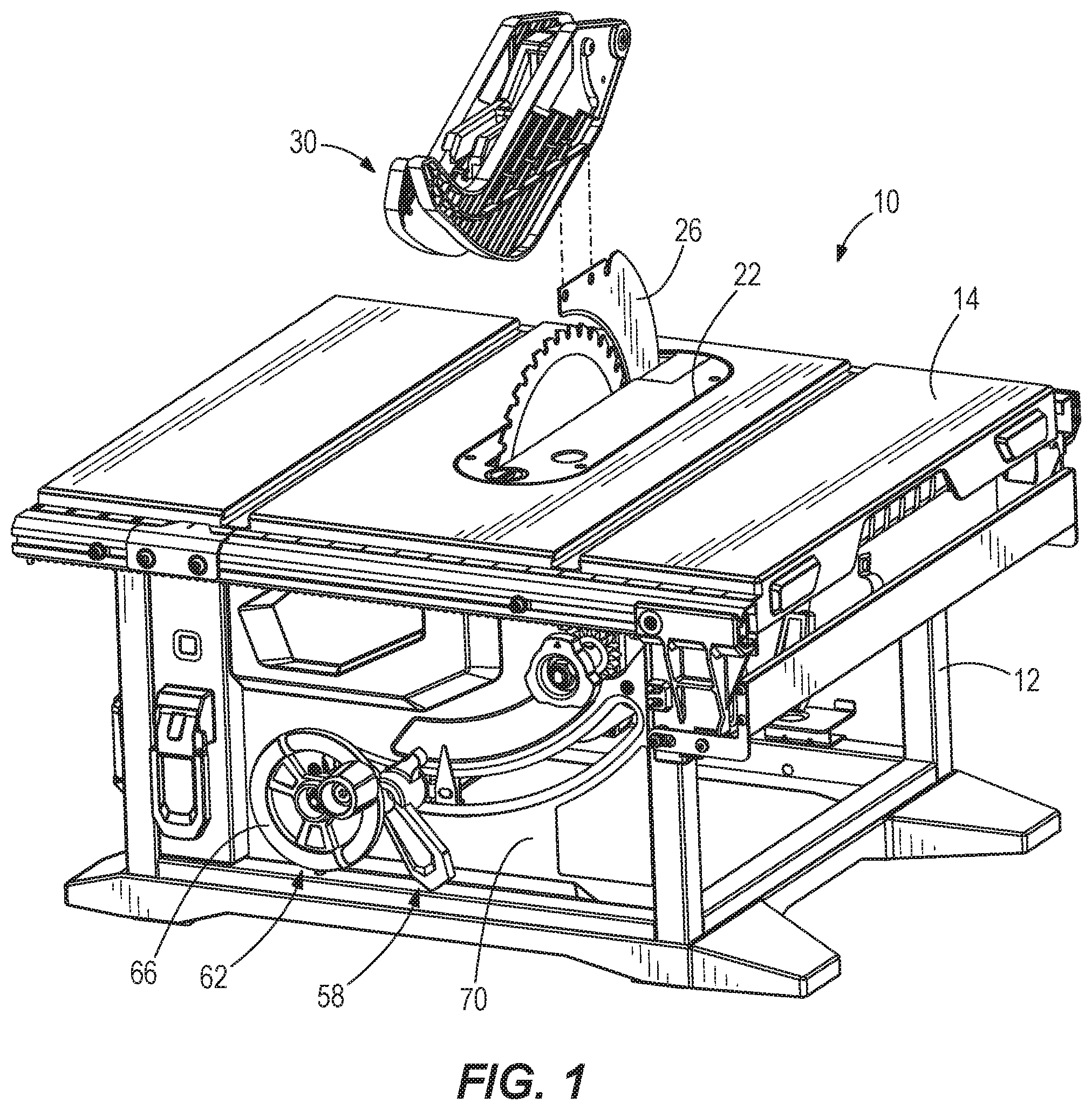
This application is a continuation of U.S. patent application Ser. No. 15/947,985 filed on Apr. 9, 2018, the entire content of which is incorporated herein by reference. The present invention relates generally to power tools, and in particular to improvements for power table saws. Table saws are commonly used power tools in the construction and wood working industries. When a saw blade of the table saw cuts a workpiece, the height and angle of the saw blade relative to the workpiece determines the depth and angle of cut into the workpiece. The height and orientation of the saw blade can be adjusted relative to a working surface of the table saw (and therefore the workpiece) through height and bevel adjustment mechanisms. Also, depending on the desired workpiece cutting operation, various components may be added or removed from the table saw to facilitate the cutting operation. Even further, the saw blade may be changed with a different saw blade depending upon the desired workpiece cutting operation or the material of the workpiece being cut. The present invention provides, in another aspect, a table saw including a table, a spindle rotatably coupled to the table for driving a saw blade extending through an opening in the table, at least one flange plate coupled for co-rotation with the spindle for clamping the saw blade to the spindle, and an actuator movable relative to the spindle between a release position and a lockout position. In the release position, the actuator is disengaged from the spindle. In the lockout position, the actuator is engaged with the spindle or the flange plate to prevent rotation of the spindle to facilitate changing the saw blade. The table saw further includes a spring biasing the actuator toward the release position. The present invention provides, in another aspect, a table saw including a table and a saw unit movably coupled underneath the table. The saw unit includes a spindle rotatably coupled to the table for driving a saw blade extending through an opening in the table and at least one flange plate coupled for co-rotation with the spindle for clamping the saw blade to the spindle. The table saw further includes a riving knife extending through the opening in the table and aligned with the saw blade extending through the opening, and a quick-release assembly selectively coupling the riving knife to the table. The quick-release assembly includes a mounting plate coupled to the table, a clamping plate that is movable relative to the mounting plate between a clamping position and a release position, a pin having a first end coupled for movement with the clamping plate, a handle pivotably coupled to a second end of the pin and including a cam portion engageable with the saw unit, wherein the clamping plate is movable between the clamping position and the release position in response to pivoting movement of the handle. In the clamping position, the riving knife can be clamped between the mounting plate and the clamping plate to secure the riving knife to the table. In the release position, the riving knife is releasable from the table. The table saw further includes an actuator movable relative to the spindle between a release position, in which the actuator is disengaged from the spindle, and a lockout position, in which the actuator is engaged with the spindle or the flange plate to prevent rotation of the spindle to facilitate changing the saw blade. The table saw further includes a spring biasing the actuator toward the release position. The present invention provides, in another aspect, a table saw including a table, a saw unit movably coupled underneath the table, a riving knife extending through an opening in the table and aligned with a saw blade extending through the opening, and a quick-release assembly selectively coupling the riving knife to the table. The quick-release assembly includes a mounting plate coupled to the table, a clamping plate that is movable relative to the mounting plate between a clamping position and a release position, a pin having a first end coupled for movement with the clamping plate, and a handle pivotably coupled to a second end of the pin and having a cam portion engageable with the saw unit, wherein the clamping plate is movable between the clamping position and the release position in response to pivoting movement of the handle. In the clamping position, the riving knife can be clamped between the mounting plate and the clamping plate to secure the riving knife to the table. In the release position, the riving knife is releasable from the table. The table saw further includes a blade height adjustment mechanism operable to raise and lower the saw unit relative to the table. The blade height adjustment mechanism includes a first drive shaft defining a first rotational axis to which a first bevel gear is coupled for co-rotation, and a second drive shaft defining a second rotational axis to which a second bevel gear is coupled for co-rotation. The second rotational axis is perpendicular to the first rotational axis, and the second drive shaft is threaded to the saw unit such that rotation of the second drive shaft moves the saw unit in a direction parallel to the second rotational axis. The first and second bevel gears are meshed for transferring torque from the first drive shaft to the second drive shaft. A ratio of teeth on the second bevel gear to the teeth on the first bevel gear, respectively, is between about 0.5:1 and about 0.75:1. The present invention provides, in another aspect, a table saw including a table and a saw unit movably coupled underneath the table. The saw unit includes a spindle rotatably coupled to the table for driving a saw blade extending through an opening in the table, and at least one flange plate coupled for co-rotation with the spindle for clamping the saw blade to the spindle. The table saw further includes a blade height adjustment mechanism operable to raise and lower the saw unit relative to the table. The blade height adjustment mechanism includes a first drive shaft defining a first rotational axis to which a first bevel gear is coupled for co-rotation, and a second drive shaft defining a second rotational axis to which a second bevel gear is coupled for co-rotation. The second rotational axis is perpendicular to the first rotational axis, and the second drive shaft is threaded to the saw unit such that rotation of the second drive shaft moves the saw unit in a direction parallel to the second rotational axis. the first and second bevel gears are meshed for transferring torque from the first drive shaft to the second drive shaft. A ratio of teeth on the second bevel gear to the teeth on the first bevel gear, respectively, is between about 0.5:1 and about 0.75:1. The table saw further includes an actuator movable relative to the spindle between a release position, in which the actuator is disengaged from the spindle, and a lockout position, in which the actuator is engaged with the spindle or the flange plate to prevent rotation of the spindle to facilitate changing the saw blade. The table saw further includes a spring biasing the actuator toward the release position. Before any embodiments of the invention are explained in detail, it is to be understood that the invention is not limited in its application to the details of construction and the arrangement of components set forth in the following description or illustrated in the following drawings. The invention is capable of other embodiments and of being practiced or of being carried out in various ways. Also, it is to be understood that the phraseology and terminology used herein is for the purpose of description and should not be regarded as limiting. With reference to With reference to With reference to With continued reference to As shown in With reference to With continued reference to With reference to With reference to With reference to When the pin 154 and the attached clamping plate 142 are located in a clamping position coinciding with a relatively large radius of contact R of the cam surface 190 ( Various features of the invention are set forth in the following claims. A table saw includes a table, a saw unit movably coupled underneath the table, a riving knife extending through the table, and a quick-release assembly selectively coupling the riving knife to the table. The quick-release assembly includes a mounting plate coupled to the table and a clamping plate movable relative to the mounting plate between a clamping position, in which the riving knife is clamped between the mounting plate and the clamping plate to secure the riving knife to the table, and a release position, in which the riving knife is releasable from the table. The quick-release assembly further includes a pin coupled for movement with the clamping plate and a handle pivotably coupled to the pin. The pin has a cam portion engageable with the saw unit. The clamping plate is movable between the clamping position and the release position in response to pivoting movement of the handle. 1. A table saw comprising:
a table; a spindle rotatably coupled to the table for driving a saw blade extending through an opening in the table; at least one flange plate coupled for co-rotation with the spindle for clamping the saw blade to the spindle; an actuator movable relative to the spindle between a release position, in which the actuator is disengaged from the spindle, and a lockout position, in which the actuator is engaged with the spindle or the flange plate to prevent rotation of the spindle to facilitate changing the saw blade; and a spring biasing the actuator toward the release position. 2. The table saw of 3. The table saw of 4. The table saw of 5. The table saw of 6. The table saw of 7. The table saw of 8. The table saw of 9. The table saw of 10. The table saw of 11. The table saw of 12. The table saw of 13. The table saw of 14. The table saw of 15. A table saw comprising:
a table; a saw unit movably coupled underneath the table, the saw unit including
a spindle rotatably coupled to the table for driving a saw blade extending through an opening in the table, and at least one flange plate coupled for co-rotation with the spindle for clamping the saw blade to the spindle; a riving knife extending through the opening in the table and aligned with the saw blade extending through the opening; a quick-release assembly selectively coupling the riving knife to the table, the quick-release assembly including
a mounting plate coupled to the table, a clamping plate that is movable relative to the mounting plate between a clamping position, in which the riving knife can be clamped between the mounting plate and the clamping plate to secure the riving knife to the table, and a release position, in which the riving knife is releasable from the table, a pin having a first end coupled for movement with the clamping plate, and a handle pivotably coupled to a second end of the pin and including a cam portion engageable with the saw unit, wherein the clamping plate is movable between the clamping position and the release position in response to pivoting movement of the handle; an actuator movable relative to the spindle between a release position, in which the actuator is disengaged from the spindle, and a lockout position, in which the actuator is engaged with the spindle or the flange plate to prevent rotation of the spindle to facilitate changing the saw blade; and a spring biasing the actuator toward the release position. 16. The table saw of a blade height adjustment mechanism operable to raise and lower the saw unit relative to the table, the blade height adjustment mechanism including
a first drive shaft defining a first rotational axis to which a first bevel gear is coupled for co-rotation, and a second drive shaft defining a second rotational axis to which a second bevel gear is coupled for co-rotation, wherein the second rotational axis is perpendicular to the first rotational axis, wherein the second drive shaft is threaded to the saw unit such that rotation of the second drive shaft moves the saw unit in a direction parallel to the second rotational axis, wherein the first and second bevel gears are meshed for transferring torque from the first drive shaft to the second drive shaft, and wherein a ratio of teeth on the second bevel gear to the teeth on the first bevel gear, respectively, is between about 0.5:1 and about 0.75:1. 17. A table saw comprising:
a table; a saw unit movably coupled underneath the table; a riving knife extending through an opening in the table and aligned with a saw blade extending through the opening; a quick-release assembly selectively coupling the riving knife to the table, the quick-release assembly including
a mounting plate coupled to the table, a clamping plate that is movable relative to the mounting plate between a clamping position, in which the riving knife can be clamped between the mounting plate and the clamping plate to secure the riving knife to the table, and a release position, in which the riving knife is releasable from the table, a pin having a first end coupled for movement with the clamping plate, and a handle pivotably coupled to a second end of the pin and including a cam portion engageable with the saw unit, wherein the clamping plate is movable between the clamping position and the release position in response to pivoting movement of the handle; a blade height adjustment mechanism operable to raise and lower the saw unit relative to the table, the blade height adjustment mechanism including
a first drive shaft defining a first rotational axis to which a first bevel gear is coupled for co-rotation, and a second drive shaft defining a second rotational axis to which a second bevel gear is coupled for co-rotation, wherein the second rotational axis is perpendicular to the first rotational axis, wherein the second drive shaft is threaded to the saw unit such that rotation of the second drive shaft moves the saw unit in a direction parallel to the second rotational axis, wherein the first and second bevel gears are meshed for transferring torque from the first drive shaft to the second drive shaft, and wherein a ratio of teeth on the second bevel gear to the teeth on the first bevel gear, respectively, is between about 0.5:1 and about 0.75:1. 18. A table saw comprising:
a table; a saw unit movably coupled underneath the table, the saw unit including
a spindle rotatably coupled to the table for driving a saw blade extending through an opening in the table, and at least one flange plate coupled for co-rotation with the spindle for clamping the saw blade to the spindle; a blade height adjustment mechanism operable to raise and lower the saw unit relative to the table, the blade height adjustment mechanism including
a first drive shaft defining a first rotational axis to which a first bevel gear is coupled for co-rotation, and a second drive shaft defining a second rotational axis to which a second bevel gear is coupled for co-rotation, wherein the second rotational axis is perpendicular to the first rotational axis, wherein the second drive shaft is threaded to the saw unit such that rotation of the second drive shaft moves the saw unit in a direction parallel to the second rotational axis, wherein the first and second bevel gears are meshed for transferring torque from the first drive shaft to the second drive shaft, and wherein a ratio of teeth on the second bevel gear to the teeth on the first bevel gear, respectively, is between about 0.5:1 and about 0.75:1; an actuator movable relative to the spindle between a release position, in which the actuator is disengaged from the spindle, and a lockout position, in which the actuator is engaged with the spindle or the flange plate to prevent rotation of the spindle to facilitate changing the saw blade; and a spring biasing the actuator toward the release position.CROSS-REFERENCE TO RELATED APPLICATIONS
FIELD OF THE INVENTION
BACKGROUND OF THE INVENTION
SUMMARY OF THE INVENTION
BRIEF DESCRIPTION OF THE DRAWINGS
DETAILED DESCRIPTION