Water Flow Diversion Apparatus
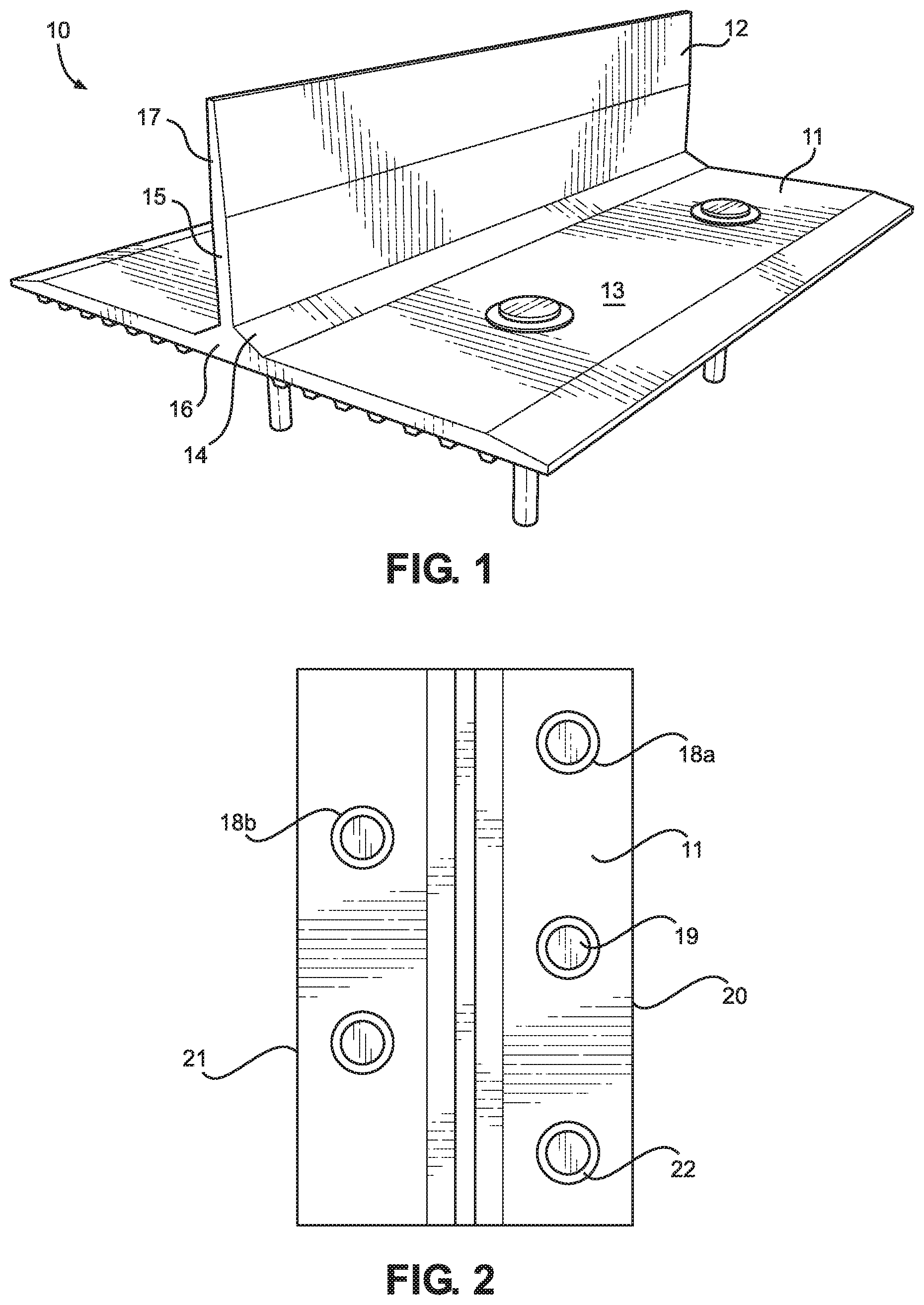
This application claims the benefit of U.S. Provisional Application No. 62/905,807 filed on Sep. 25, 2019. The above identified patent application is herein incorporated by reference in its entirety to provide continuity of disclosure. The present invention relates to a water flow diversion apparatus. More specifically, the present invention provides an installable apparatus for diverting water, such as flood waters, away from a desired area. In many areas, it is common to experience large volume of rain, snow, or other precipitation. As rain falls and as snow melts, the result is a flow of running water from a higher ground level to a lower ground level. As running water flows, it can be destructive in numerous ways. For example, large volumes of water can accumulate and flow along loose gravel, unpaved and naturally formed roads and driveways, causing them to wash out or causing the formation of large ruts in these roadways. Steep driveways, in particular, are susceptible to washouts, as the water flow passing over them is higher than that of a less steep driveway. Over time, the condition of these roads and driveways may diminish to the point where they are undrivable. In some cases, a vehicle could become stuck in the road or driveway, requiring the use of a tow truck or a winch to get out. In addition to the risks to vehicles traveling in the roads and driveways, the cost of repairing such damage can be significant. In some cases, the entire road section or driveway may need to be replaced to return the road or driveway to a drivable condition. Therefore, there is a defined need amongst the known prior art devices and methods for an improved apparatus for preventing water damage to roads and driveways that are particularly susceptible to such damage. In view of the foregoing disadvantages inherent in the known types of water redirection devices and methods now present in the prior art, the present invention provides a water flow diversion apparatus wherein the same can be utilized for providing convenience for the user when redirecting a running flow of water away from a desired area. The present system comprises a planar base. The planar base is configured to secure to or below a ground surface. A barrier extends upward from the planar base. The barrier is perpendicular to the base, such that the barrier is maintained in a substantially vertical position. Furthermore, the barrier is configured to redirect a flow of water that comes into contact with the barrier, or the portion of the barrier that extends above the ground surface on which it is installed. The barrier comprises a pair of support braces on each side of the planar base. The support braces provide additional support to the barrier by spreading out the impact on the barrier amongst a greater area of the planar base. Although the characteristic features of this invention will be particularly pointed out in the claims, the invention itself and manner in which it may be made and used may be better understood after a review of the following description, taken in connection with the accompanying drawings wherein like numeral annotations are provided throughout. Reference is made herein to the attached drawings. Like reference numerals are used throughout the drawings to depict like or similar elements of the water flow diversion apparatus. The figures are intended for representative purposes only and should not be considered to be limiting in any respect. Referring now to A barrier 12 extends upward from the top surface 13 of the planar base 11. A lower portion 15 of the barrier 12 extends upward perpendicularly from the planar base 11 forming a joint 16 that is roughly 90 degrees. Structurally, the barrier 12 is of any suitable size, shape, or configuration for redirecting a water current exerted upon the barrier 12. In some embodiments, the barrier 12 is of a uniform thickness along the entire length and height of the barrier 12. However, in alternate embodiments, the thickness of the barrier may vary. For example, in the demonstrated embodiment, the barrier 12 is tapered, such that a greater thickness is provided at the lower portion 15 of the barrier 12 compared to the upper portion 17 of the barrier 12. As such, greater stability is provided to the lower portion 15 of the barrier 12, adjacent to the joint 16 and the planar base 11. Furthermore, in the demonstrated embodiment, each side of the planar base 11 tapers from the barrier 12 to a distal end of the planar base 11. As such, additional structural security is provided to the joint 16. In the illustrated embodiment, the barrier 12 and the planar base 11 are a single, unitary member, such as to reduce the risk of separation between the planar base 11 and the barrier 12 at the joint 16 thereof. In other embodiments, however, the barrier 12 can be separated from the planar base 11, such as to enable easier and more efficient storage and transport of the water flow diversion apparatus 10. Additionally, in some embodiments, the planar base 11 and the barrier 12 may be made of an identical material, while in other embodiments the planar base 11 and the barrier 12 may be made of different materials. For example, a heavier material may be utilized on the planar base 11 and a waterproof flexible material may be used for the barrier 12. A pair of support braces 14 are disposed on each side of the planar base 11. The pair of support braces 14 are in operable connection with the planar base 11 and with the barrier 12. As such, additional structural stability and strength are provided to the barrier 12 such that the barrier 12 will maintain position when subjected to the force of a high volume or high velocity water current. In the demonstrated embodiment, the pair of support braces 14 are of a greater thickness than the barrier 12. This allows for the pair of support braces 14 to strengthen the barrier 12 primarily at the lower portion 15 of the barrier 12, where due to leverage exerted on the joint 16 of the planar base 11 and the barrier 12, separation or tearing would be most likely to occur. In the illustrated embodiment, the pair of support braces 14 are of an identical length as the barrier 12, as well as the planar base 11. However, in alternate embodiments, the planar base 11, the barrier 12, and the pair of support braces 14 may be of different lengths. For example, in one embodiment, the pair of support braces 14 may be of a lesser length than the length of the barrier 12 and of the planar base 11 in order to allow for a level of flexion or to allow the water flow diversion apparatus 10 to be curved. Additionally, in some embodiments, the barrier 12 and the planar base 11 are of an identical length, such as to provide a maximum surface area of the barrier 12 to redirect a water current. Referring now to Specifically, in the illustrated embodiment, the plurality of apertures 18 Referring now to Referring now to Once the planar base 11 is properly positioned and secured, the barrier 12 will be presented in the desired location to block and redirect a water current. When a weighted object is placed onto the planar base 11 or the planar base 11 is buried underground to further secure the position of the water flow diversion apparatus 10, the barrier 12 may be entirely above ground, or may be partially underground. Ideally the barrier 12 should be provided to a height greater than the height of an expected water current. The water flow diversion apparatus 10 may be a permanent installation upon a desired surface or may be temporarily deployed in the event of flash floods or heavy rains. It is therefore submitted that the instant invention has been shown and described in various embodiments. It is recognized, however, that departures may be made within the scope of the invention and that obvious modifications will occur to a person skilled in the art. With respect to the above description then, it is to be realized that the optimum dimensional relationships for the parts of the invention, to include variations in size, materials, shape, form, function and manner of operation, assembly and use, are deemed readily apparent and obvious to one skilled in the art, and all equivalent relationships to those illustrated in the drawings and described in the specification are intended to be encompassed by the present invention. Therefore, the foregoing is considered as illustrative only of the principles of the invention. Further, since numerous modifications and changes will readily occur to those skilled in the art, it is not desired to limit the invention to the exact construction and operation shown and described, and accordingly, all suitable modifications and equivalents may be resorted to, falling within the scope of the invention. A water flow diversion apparatus is provided. The water flow diversion apparatus includes a planar base. The planar base is installable upon or below a ground surface. A barrier extends upward from the planar base. The barrier is designed to redirect the flow of water when the water contacts the barrier. The barrier also includes a pair of support braces. The support braces are secured between the planar base and the barrier so that they provide additional support to the barrier to withstand the impact of water flow. 1) A water flow diversion apparatus, comprising:
a planar base; a barrier extending perpendicularly upward from the planar base; the barrier comprising a pair of support braces on each side of the planar base; the support braces secured to the planar base and to the barrier. 2) The water flow diversion apparatus of 3) The water flow diversion apparatus of 4) The water flow diversion apparatus of 5) The water flow diversion apparatus of 6) The water flow diversion apparatus of 7) The water flow diversion apparatus of 8) The water flow diversion apparatus of 9) The water flow diversion apparatus of 10) The water flow diversion apparatus of 11) The water flow diversion apparatus of 12) The water flow diversion apparatus of 13) The water flow diversion apparatus of 14) The water flow diversion apparatus of 15) The water flow diversion apparatus of 16) The water flow diversion apparatus of 17) The water flow diversion apparatus of 18) A method of diverting water from a surface, comprising:
providing a water flow diversion apparatus; the water flow diversion apparatus comprising a planar base, a barrier extending upward from the planar base and a pair of support braces on each lateral side of the barrier; securing the planar base of the water flow diversion apparatus to a ground surface. 19) The method of diverting water from a surface of 20) The method of diverting water from a surface of CROSS REFERENCE TO RELATED APPLICATIONS
BACKGROUND OF THE INVENTION
SUMMARY OF THE INVENTION
BRIEF DESCRIPTION OF THE DRAWINGS
DETAILED DESCRIPTION OF THE INVENTION