PUPIL ELLIPSE-BASED, REAL-TIME IRIS LOCALIZATION
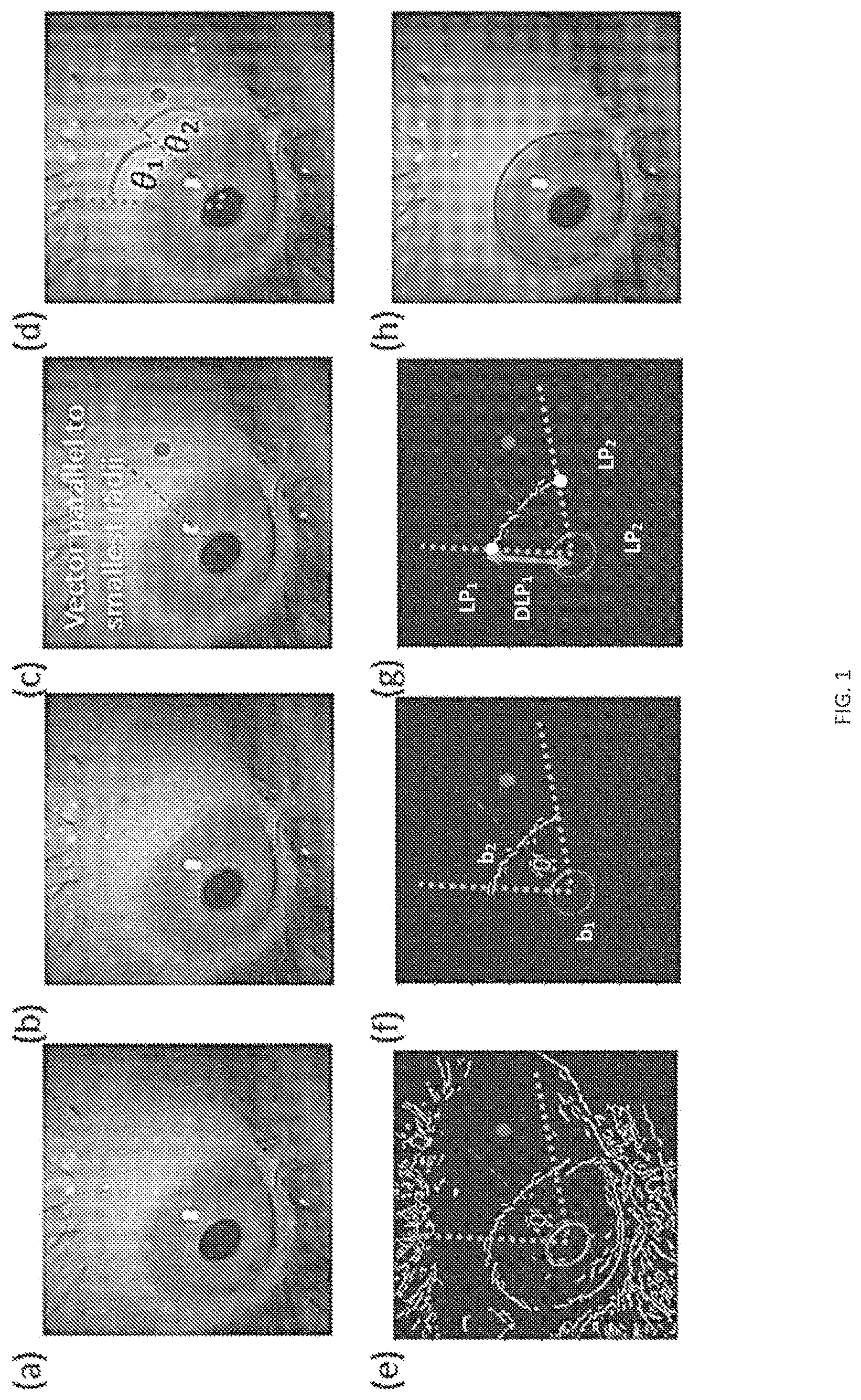
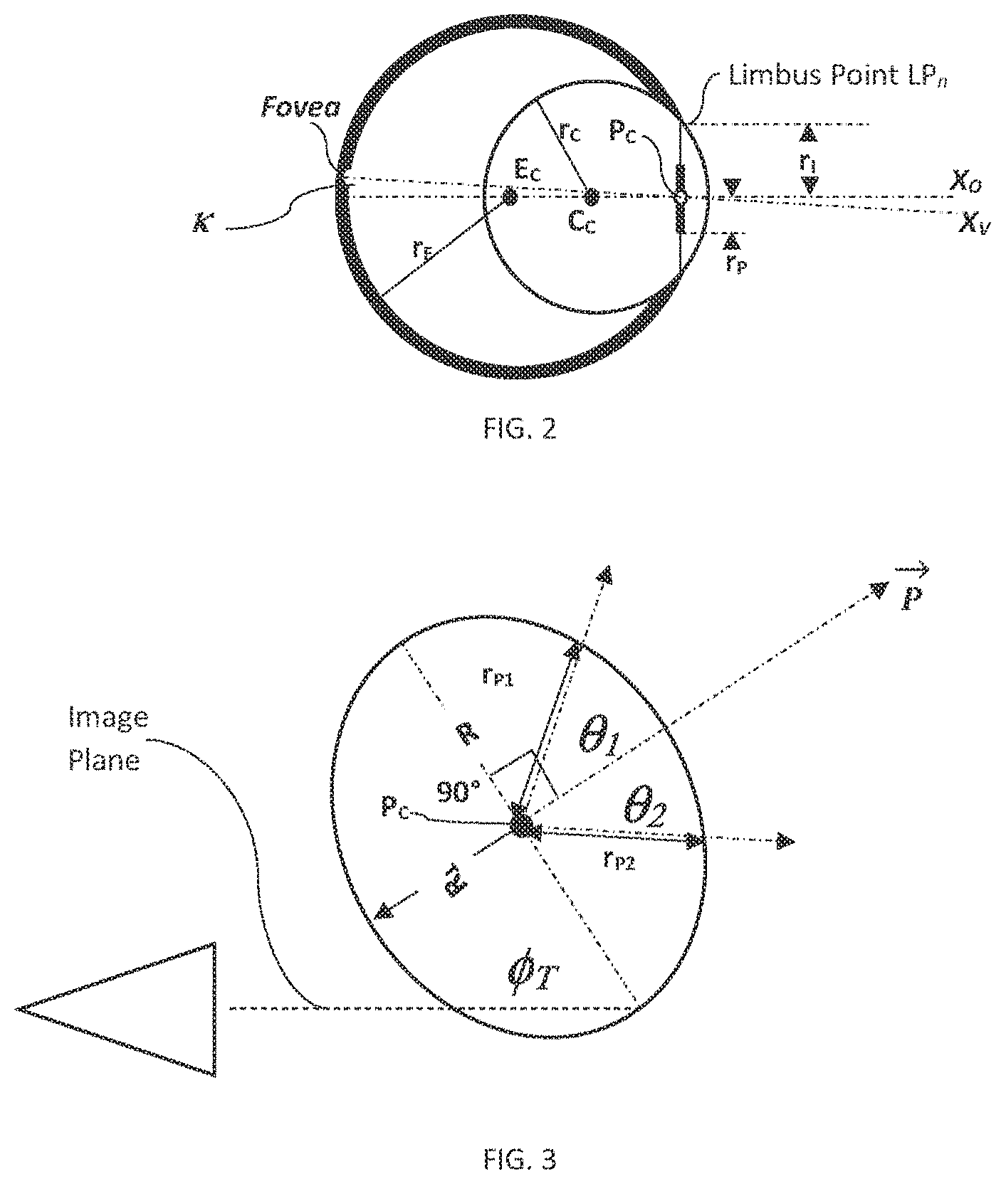
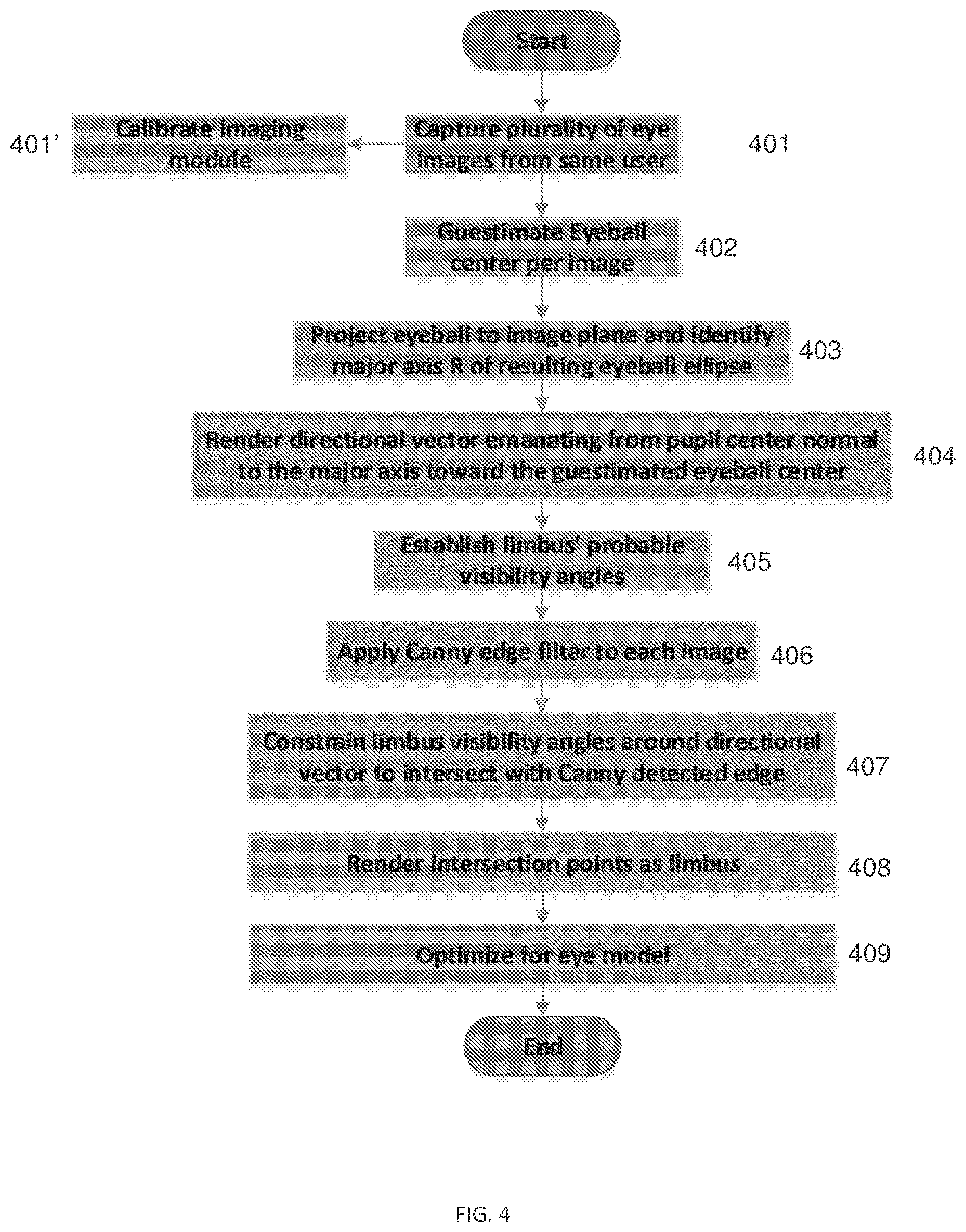
The present application claims the benefit of priority to U.S. Provisional Application No. 63/052,480, entitled PUPIL ELLIPSE-BASED, REAL-TIME IRIS LOCALIZATION, naming Uri Wollner, Nadav Arbel, Tsahi Mizrahi, Soliman Nasser, Artyom Borzin, Gilad Drozdov and Oren Haimovitch-Yogev as inventors, filed 16 Jul. 2020, which is currently co-pending, the content of which is hereby incorporated by reference in its entirety. A portion of the disclosure herein below contains material that is subject to copyright protection. The copyright owner has no objection to the reproduction by anyone of the patent document or the patent disclosure as it appears in the Patent and Trademark Office patent files or records, but otherwise reserves all copyright rights whatsoever. The disclosure is directed to systems, methods and programs for use in gaze estimation, eye tracking, and/or calibration of head-mounted displays (HMD). More specifically, the disclosure is directed to systems, methods and programs for developing real-time user-specific eye model based on iris localization using solely pupil-ellipse analysis. Eye tracking and gaze estimation can, and is used in a large area of applications from ophthalmology, disabled's assistive technologies, through advertising, cybersecurity authentication, to gaming and virtual reality. Precisely detecting the pupil's contour and the eyeball center is the first step in many of the tasks associated with these applications, hence the need to perform the detection and information analysis accurately. Typically, camera-based eye tracking approaches are normally divided into two stages: eye/pupil detection and gaze estimation based on that information. Likewise, gaze-estimation can be divided into two approaches; 2D appearance/feature-based and 3D model-based. Appearance/feature-based methods are typically based on the assumption that similar eye appearances/features (e.g., eye corners, elliptical tilt and dimensions), correspond to similar gaze positions/directions, from which different mapping functions can be learned to perform gaze estimation. Conversely, 3D model-based methods perform gaze estimation based on a 3D geometric eye model, which mimics the structure and function of human vision system. However, the practical utility of both these methods (appearance/feature based and model-based) can be significantly limited due, for example, to complex system (e.g., IR illumination source, stereo vision system, 3D sensors setup and the like) and sensitivity to environmental settings such as light, distance and head pose. Moreover, using current technology, these methods may either; have strong limiting assumptions, are commercially unfeasible, or are insufficiently accurate. These and other shortcomings of the existing technologies are sought to be resolved herein. Disclosed, in various embodiments, are systems, methods and programs for developing real-time user-specific eye model from a plurality of images, based on iris localization and using solely pupil-ellipse analysis. In an embodiment provided herein is a computerized method of establishing a user-specific eye model, implementable in a system comprising a head-mounted imaging module (HMI) configured for an off-axis capture of the user's eyes, a central processing module in communication with an operator interface module, an edge detection module, a rendering module, and a display, the method comprising: using the HMI, capturing a plurality of images of the user's eye; for each image, estimating an eyeball center EC, projecting eyeball to image plane, thereby identifying a major axis R of projected pupil ellipse; rendering a directional vector{right arrow over (P)}, emanating from pupil center being normal to the pupil's major axis R toward the eyeball center EC, from pupil center in each image, rendering limbus visibility angle intersected by directional vector, forming limbus' probable visibility angles θ1, and θ2; using the edge detection module, applying edge detection to each image, forming a plurality of edge rendered images; in each edge rendered image, rendering a pair of rays inscribing limbus visibility angle θPL: detecting the intersection point of each of the pair of rays with the second edge detected, thereby detecting limbus points LP1, and LP2for each edge rendered image, and using the detected limbus points from all captured images; compiling the user-specific eye-model wherein a smaller circle intersects a larger circle in two intersection points corresponding to the user-specific limbus. In another embodiment, provided herein is a processor-readable media implementable in a computerized system comprising a head-mounted imaging module (HMI) configured for an off-axis capture of the user's eyes, a central processing module in communication with an operator interface module, an edge detection module, a rendering module, and a display, the central processing module further comprising a non-volatile memory having thereon the processor readable media with a set of instructions configured, when executed to cause the central processing module to: using the HMI, capture a plurality of images of the user's eye, for each image, estimate an eyeball center EC; project eyeball to image plane, and identify a major axis R of projected pupil ellipse; render a directional vector{right arrow over (P)}, emanating from pupil center being normal to the pupil's major axis R toward the eyeball center EC, from pupil center in each image, render limbus visibility angle θPL, intersected by directional vector, forming limbus' probable visibility angles θ1, and θ2; using the edge detection module, apply edge detection to each image, forming a plurality of edge rendered images, in each edge rendered image, render a pair of rays inscribing limbus visibility angle θPL: detect the intersection point of each of the pair of rays with the second edge detected, thereby detecting limbus points LP1, and LP2for each edge rendered image; and using the detected limbus points from all captured images; compile the user-specific eye-model wherein a smaller circle intersects a larger circle in two intersection points corresponding to the user-specific limbus. These and other features of the systems, methods and programs for developing real-time user-specific eye model based on iris localization using solely pupil-ellipse analysis, will become apparent from the following detailed description when read in conjunction with the figures and examples, which are exemplary, not limiting. For a better understanding of systems, methods and programs for developing real-time user-specific eye model based on iris localization using solely pupil-ellipse analysis, with regard to the embodiments thereof, reference is made to the accompanying examples and figures, in which: Provided herein are embodiments of systems, methods and programs for developing real-time user-specific eye model based on iris localization using solely pupil-ellipse analysis. The provided systems, methods and programs are adapted, when implemented, to provide an estimate of the location the eyeball center and eyeball radius solely based on iris points localized in multiple images. Therefore, the user does not have to recalibrate the system every time the head-mounted display (HMD) moves, or if the user removes the HMD and then puts it back on. The provided systems, methods and programs are adapted, when implemented, to provide an estimate of the location the eyeball center and eyeball radius solely based on iris points localized in multiple images. Therefore, the user does not have to recalibrate the system every time the head-mounted display (HMD) moves, or if the user removes the HMD and then puts it back on. The disclosed systems, methods and programs (processor-readable media e.g.,) can be extremely beneficial for user experience in HMD-type setting. The continuous and automatic calibration of the user's eyeball center without the need for user's input is an advantage. Moreover, the disclosed and claimed technology is not only limited to HMD setting, but can also be altered to provide a solution for eyeball location other related applications, such as in webcam setting as well, where user attention and saliency analysis may be desired. Included in the term “head-mounted display” (HMD) refers to visors, goggles and spectacles worn directly on the head, and also such articles carried indirectly on the head by being mounted on a helmet, or other head gear. It also comprises visors, goggles and viewing windows which are built into helmets or other head gear. Moreover, HMDs can also describe one or more of the following: a wearable computer having a display, head mounted electronic device, a head-coupled display, a head-mounted computer with a display. The HMD, which his worn on a head of a user or which is a part of a helmet, can have a small display optic in front of one (monocular display device) or each eye (binocular display device). Also, the HMD can have either one or two small displays with lenses and semi-transparent mirrors embedded in a helmet, eye-glasses (also known as data glasses) or visor. The display units can be miniaturized and may include a Liquid Crystal Display (LCD), Organic Light-Emitting Diode (OLED) display, or the like. Some vendors employ multiple micro-displays to increase total resolution and field of view. Some other HMDs do not use a traditional display at all and instead project light directly into the user's eyes. Also included in the HMD are contact lenses equipped with imaging and connectivity (brain, remote) capabilities. Accordingly and in an embodiment illustrated in In the compilation of the user-specific eye model, the recorded limbus locations or points LPnof all captured images are used in an optimization scheme to construct a 3D eye model consisting of sphere and a circular contour lying on the surface of the sphere (SEE e.g., Where, EM is the eye model, (EM) is the rotation matrix applied to the eye model, and (⋅) is the projection of the 3D iris onto the image plane. Furthermore, identifying the major axis R (see e.g., As illustrated in The following is an example of an algorithm that can be used to fit detected pupil ellipse: Finding the pupil center can be done, for example whereby for each eye image, using the imaging module, the unprojected pupil circle (pi;ni;ri) is established, where i is the index of the individual initially captured image (the ithimage), with the aim to find a single sphere which is tangent to every ithpupil circle. Since each pupil circle is tangent to the sphere, the normals of the ithcircles, ni, will be radial vectors of the sphere, and thus their intersection can be considered as the unifying sphere's and thus the pupil's center. Other methods for finding the ellipse boundaries and center can be used with the methods provided herein. These can be, for example at least one of: using a monocular image module that zooms in on only one eye of the user, capture the images and discern a single unprojected circle, and where pupil center is computed based solely on points related to the pupil boundary computing a curvature value for each detected boundary point. Returning now to In an embodiment, the step of applying edge detection to each image, forming a plurality of edge rendered images, comprises using a Canny edge detector 406, referring to a method that is widely used in computer vision to locate sharp intensity changes and to find object boundaries in an image. The Canny edge detector classifies a pixel as an edge once it is determined that the gradient magnitude of the pixel is larger than those of pixels at both its sides in the direction of maximum intensity change Consequently, since edges are marked at maxima in gradient magnitude, a Gaussian-smoothed image is produced by applying a Gaussian filter, having, for example, a kernel of no less than 5 pixels by 5 pixels. A typical Canny edge detection can be:
Turning now to It is noted that the term “imaging module” as used herein means a head mounted device unit that includes a plurality of built-in image and/or optic sensors and outputs electrical signals, which have been obtained through photoelectric conversion, as an image, while the term “module” refers to software, hardware, for example, a processor, or a combination thereof that is programmed with instructions for carrying an algorithm or method. The modules described herein may communicate through a wired connection, for example, a hard-wired connections, a local area network, or the modules may communicate wirelessly. The imaging module may comprise charge coupled devices (CCDs), a complimentary metal-oxide semiconductor (CMOS) or a combination comprising one or more of the foregoing. If static images are required, the imaging module can comprise a digital frame camera, where the field of view (FOV) can be predetermined by, for example, the camera size and the distance from the subject's face. The cameras used in the imaging modules of the systems and methods disclosed, can be a digital camera. The term “digital camera” refers in an embodiment to a digital still camera, a digital video recorder that can capture a still image of an object and the like. The digital camera can comprise an image capturing unit or module, a capture controlling module, a processing unit (which can be the same or separate from the central processing module). Capturing the image can be done with, for example image capturing means such as a CCD solid image capturing device of the full-frame transfer type, and/or a CMOS-type solid image capturing device, or their combination. Furthermore and in another embodiment, imaging module can have a single optical (e.g., passive) sensor having known distortion and intrinsic properties, obtained for example, through a process of calibration. These distortion and intrinsic properties are, for example, modulation-transfer function (MTF), focal-length for both axes, pixel-size and pixel fill factor (fraction of the optic sensor's pixel area that collects light that can be converted to current), lens distortion (e.g., pincushion distortion, barrel distortion), sensor distortion (e.g., pixel-to-pixel on the chip), anisotropic modulation transfer functions, space-variant impulse response(s) due to discrete sensor elements and insufficient optical low-pass filtering, horizontal line jitter and scaling factors due to mismatch of sensor-shift- and analog-to-digital-conversion-clock (e.g., digitizer sampling), noise, and their combination. In an embodiment, determining these distortion and intrinsic properties is used to establish an accurate sensor model, which can be used for calibration algorithm to be implemented. To facilitate some operations of the methods and programs described, the system can further comprise a graphic processing module (GPM), in communication with the central processing module and the processor. It should be understood though, that the graphics processing module may or may not be a separate integrated circuit. The systems used herein is a computerized systems; further comprising a central processing module; a display module, and a user interface module. The Display modules, which can include display elements, which may include any type of element which acts as a display. A typical example is a Liquid Crystal Display (LCD). LCD for example, includes a transparent electrode plate arranged on each side of a liquid crystal. There are however, many other forms of displays, for example OLED displays and Bi-stable displays. New display technologies are also being developed constantly. Therefore, the term display should be interpreted widely and should not be associated with a single display technology. Also, the display module may be mounted on a printed circuit board (PCB) of an electronic device, arranged within a protective housing and the display module is protected from damage by a glass or plastic plate arranged over the display element and attached to the housing. Additionally, “user interface module” broadly refers to any visual, graphical, tactile, audible, sensory, or other means of providing information to and/or receiving information from a user or other entity. For example, a set of instructions which enable presenting a graphical user interface (GUI) on a display module to a user for displaying and changing and or inputting data associated with a data object in data fields. In an embodiment, the user interface module is capable of displaying any data that it reads from the imaging module. As indicated, the systems implementing the methods provided, using the programs provided can further comprise a central processing module; a display module; an edge detection module, and a user interface module. The term ‘module’, as used herein, means, but is not limited to, a software or hardware component, such as a Field Programmable Gate-Array (FPGA) or Application-Specific Integrated Circuit (ASIC), which performs certain tasks. A module may advantageously be configured to reside on an addressable storage medium and configured to execute on one or more processors. Thus, a module may include, by way of example, components, such as software components, object-oriented software components, class components and task components, processes, functions, attributes, procedures, subroutines, segments of program code, drivers, firmware, microcode, circuitry, data, databases, data structures, tables, arrays, and variables. The functionality provided for in the components and modules may be combined into fewer components and modules or further separated into additional components and modules. Unless specifically stated otherwise, as apparent from the discussions, it is appreciated that throughout the specification discussions utilizing terms such as “processing,” “loading,” “in communication,” “detecting,” “calculating,” “determining”, “analyzing,” or the like, refer to the action and/or processes of a computer or computing system, or similar electronic computing device, that manipulate and/or transform data represented as physical, such as the PoR into other data similarly represented as physical layers, such as the transformed data. As indicated, provided herein is a computer program, comprising program code means for carrying out the steps of the methods described herein, as well as a computer program product (e.g., a micro-controller) comprising program code means stored on a medium that can be read by a computer, such as a hard disk, CD-ROM, DVD, USB memory stick, or a storage medium that can be accessed via a data network, such as the Internet or Intranet, when the computer program product is loaded in the main memory of a computer [or micro-controller] and is carried out by the computer [or micro controller]. Furthermore, provided herein is a computer-readable medium comprising the executable instructions disclosed. Accordingly, provided herein is processor-readable media implementable in the computerized systems described herein, whereby the central processing module further comprising a non-volatile memory having thereon the processor readable media with a set of instructions configured, when executed to cause the central processing module to: using the HMI, capture a plurality of images of the user's eye; for each image, estimate an eyeball center EC; project eyeball to image plane, and identify a major axis R of projected pupil ellipse; render a directional vector{right arrow over (P)}, emanating from pupil center being normal to the pupil's major axis R toward the eyeball center EC; from pupil center in each image, render limbus visibility angle θPL, intersected by directional vector, forming limbus' probable visibility angles θ1, and θ2; using the edge detection module, apply edge detection to each image, forming a plurality of edge rendered images; in each edge rendered image, render a pair of rays inscribing limbus visibility angle θPL: detect the intersection point of each of the pair of rays with the second edge detected, thereby detecting limbus points LP1, and LP2for each edge rendered image, and using the detected limbus points from all captured images; compile the user-specific eye-model wherein a smaller circle intersects a larger circle in two intersection points corresponding to the user-specific limbus. The term “computer-readable medium” as used herein, in addition to having its ordinary meaning, refers to any medium that participates in providing instructions to a processor for execution. Such a medium may take many forms, including but not limited to, non-volatile media and volatile media. Non-volatile media can be, for example, optical or magnetic disks, such as a storage device. Volatile media includes dynamic memory, such as main memory. Memory device as used in the methods, programs and systems described herein can be any of various types of memory devices or storage devices. The term “memory device” is intended to encompass an installation medium, e.g., a CD-ROM, floppy disks, or tape device; a computer system memory or random access memory such as DRAM, DDR RAM, SRAM, EDO RAM, Rambus RAM, etc.; or a non-volatile memory such as a magnetic media, e.g., a hard drive, optical storage, or ROM, EPROM, FLASH, etc. The memory device may comprise other types of memory as well, or combinations thereof. In addition, the memory medium may be located in a first computer in which the programs are executed (e.g., a training computer), and/or may be located in a second different computer [or micro controller] which connects to the first computer over a network, such as the Internet and might be even not connected and information will be transferred using USB drive. In the latter instance, the second computer may further provide program instructions to the first computer for execution. The term “memory device” can also include two or more memory devices which may reside in different locations, e.g., in different computers that are connected over a network. The term “comprising” and its derivatives, as used herein, are intended to be open ended terms that specify the presence of the stated features, elements, components, groups, integers, and/or steps, but do not exclude the presence of other unstated features, elements, components, groups, integers and/or steps. The foregoing also applies to words having similar meanings such as the terms, “including”, “having” and their derivatives. The terms “a”, “an” and “the” herein do not denote a limitation of quantity, and are to be construed to cover both the singular and the plural, unless otherwise indicated herein or clearly contradicted by context. The suffix “(s)” as used herein is intended to include both the singular and the plural of the term that it modifies, thereby including one or more of that term (e.g., the stack(s) includes one or more stack). Reference throughout the specification to “one embodiment”, “another embodiment”, “an embodiment”, and so forth, when present, means that a particular element (e.g., feature, structure, and/or characteristic) described in connection with the embodiment is included in at least one embodiment described herein, and may or may not be present in other embodiments. In addition, it is to be understood that the described elements may be combined in any suitable manner in the various embodiments. Although the foregoing disclosure for systems, methods and programs for developing real-time user-specific eye model based on iris localization using solely pupil-ellipse analysis has been described in terms of some embodiments, other embodiments will be apparent to those of ordinary skill in the art from the disclosure herein. Moreover, the described embodiments have been presented by way of example only, and are not intended to limit the scope of the embodiments. Indeed, the novel methods, programs, and systems described herein may be embodied in a variety of other forms without departing from the spirit thereof. Accordingly, other combinations, omissions, substitutions and modifications will be apparent to the skilled artisan in view of the disclosure herein. While the invention has been described in detail and with reference to specific embodiments thereof, it will be apparent to one of ordinary skill in the art that various changes and modifications can be made therein without departing from the spirit and scope thereof. Accordingly, it is intended that the present disclosure covers the modifications and variations of this invention provided they come within the scope of the appended claims and their equivalents. The disclosure relates to systems, methods and programs for developing real-time user-specific eye model based on iris localization using solely pupil-ellipse analysis. 1. A computerized method of establishing a user-specific eye model, implementable in a system comprising a head-mounted display (HMD) configured for an off-axis capture of at least one image of at least one eye of a user, the method comprising:
a. using the HMD, capturing a plurality of images of at least one of the user's eyes; b. for each image, estimating an eyeball center ECof an eyeball; c. projecting the eyeball to an image plane, thereby identifying a major axis R of a projected pupil ellipse; d. calculating a directional vector emanating from a pupil center, being normal to the major axis R, and being directed towards from the eyeball center EC;
e. from the pupil center in each image, calculating limbus visibility angle θPL, intersected by directional vector forming limbus probable visibility angles θ1, and θ2;
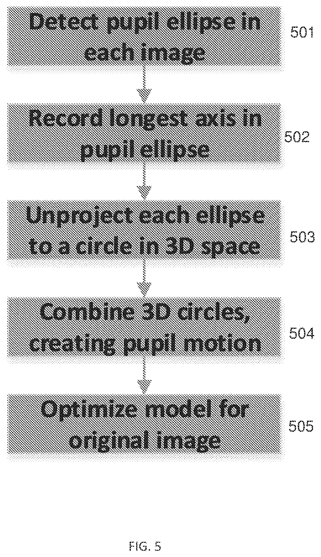
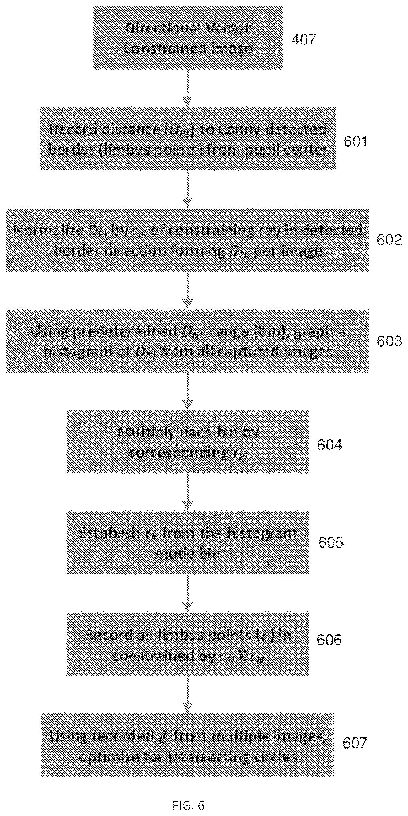
f. applying edge detection to each image, forming a plurality of edge-rendered images; g. in each edge-rendered image, calculating a pair of rays inscribing limbus visibility angle θPL: h. detecting the intersection point of each of the pair of rays with a second detected edge, thereby detecting limbus points LP1, and LP2for each edge-rendered image; and i. using the detected limbus points from a plurality of captured images, compiling the user-specific eye-model. 2. The method of a. detecting a pupil ellipse in each image; b. determining the detected ellipse's major axis length; c. unprojecting each pupil ellipse to a circle in three-dimensional (3D) space; and d. combining unprojected circles from each image, thereby forming a 3D pupil motion model. 3. The method of 4. The method of 5. The method of a. for each ray inscribing limbus visibility angle θPL, recording distance DPLqfrom the pupil center to the second detected edge in each edge-detected image thereby identifying DPL1, and DPL2, for each edge-rendered image; b. normalizing each of DPL1and DPL2, by the respective rP1and rP2, thereby identifying normalized distances DN1and DN2for each edge-rendered image; c. using a predetermined normalized distance range to establish a plurality of bins to build a histogram of DPL1and DPL2from one or more captured images; d. multiplying each bin content by its corresponding rPi; e. selecting the normalizing radius rNfrom the histogram mode bin, f. calculating limbus points (lj) detected from one or more of the captured images constrained by rPi×rN; and g. using the detected limbus points (lj) to optimize a model of intersecting circles, wherein a plane formed by an intersection of a smaller ellipse representing the pupil with a larger ellipse representing the iris is defined by the contour of the detected limbus points (lj). 6. The method of 7. The method of 8. The method of 9. The method of 10. The method of 11. A processor-readable medium implementable in a computerized system having a head-mounted display (HMD) configured for an off-axis capture of at least one image of at least one eye of a user, the processor-readable medium having a set of instructions configured, when executed, to cause the computerized system to:
a. using the HMD, capture a plurality of images of at least one of the user's eyes; b. for each image, estimate an eyeball center ECof an eyeball; c. project the eyeball to an image plane, and identify a major axis R of a projected pupil ellipse; d. calculate a directional vector emanating from a projected pupil center, being normal to the major axis R, and being directed away from the eyeball center EC;
e. from the pupil center in each image, calculate limbus visibility angle θPL, intersected by directional vector forming limbus' probable visibility angles θ1, and θ2;
f. apply edge detection to each image, forming a plurality of edge-rendered images; g. in each edge-rendered image, calculate a pair of rays inscribing limbus visibility angle θPL: h. detect the intersection point of each of the pair of rays with a second detected edge, thereby detecting limbus points LP1, and LP2for each edge-rendered image; and i. using the detected limbus points from the plurality of captured images, compile the user-specific eye-model. 12. The processor-readable medium of a. detect a pupil ellipse in each image; b. measure the detected ellipse's major axis length; c. unproject each pupil ellipse to a circle in three-dimensional (3D) space; and d. combine unprojected circles from each image, thereby forming a 3D pupil motion model. 13. The processor-readable medium of 14. The processor-readable medium of 15. The processor-readable media of a. for each ray inscribing limbus visibility angle θPL, record distance DPLqfrom the pupil center to the second detected edge in each edge-detected image thereby identifying DPL1, and DPL2, for each edge-rendered image, b. normalize each of DPL1and DPL2by the respective rP1and rP2, thereby identifying normalized distances DN1and DN2for each edge-rendered image; c. using a predetermined normalized distance range to establish a plurality of bins, build a histogram of DPL1and DPL2from one or more captured images; d. multiply each bin content by its corresponding rPi; e. select the normalizing radius rNfrom the histogram mode bin; f. calculate limbus points (lj) detected from one or more of the captured images constrained by rPi×rN; and g. using the detected limbus points (lj), optimize a model of intersecting circles, whereby a plane formed by an intersection of a smaller circle representing the pupil and a larger circle representing the iris is defined by a contour corresponding to the detected limbus points (lj). 16. The processor-readable medium of 17. The processor-readable medium of 18. The processor-readable medium of 19. The processor-readable medium of 20. The processor-readable medium of 21. A system comprising a head-mounted display operable to estimate the location of the center of an eyeball and an eyeball radius of a user based on iris points localized in multiple images and based on pupil ellipse measurements, wherein the location of the center of an eyeball and an eyeball radius provide a user-specific eye model that does not require recalibration when the head-mounted display (HMD) moves relative to the user's eye.CROSS-REFERENCE TO RELATED APPLICATIONS
COPYRIGHT NOTICE
BACKGROUND
SUMMARY
BRIEF DESCRIPTION OF THE FIGURES
DETAILED DESCRIPTION
procedure RANSAC-ELLIPSE-FIT(points, image, N, ϵ) best-ellipse ← null best-support ← − inf // Perform N RANSAC iterations repeat N times sample ← RANDOM-SAMPLE(points, 5) ellipse ← FIT-ELLIPSE(sample) // Early sample rejection If ∃(x, y) ∈ sample where ∇ellipse(x, y) · ∇image(x, y) ≤ 0 then continue // reject sample, skip this iteration end if // Iteratively refine inliers (we use M = 2) repeat M times inliers = {(x, y) ∈ points | error(ellipse, x, y) < ε} ellipse ← FIT-ELLIPSE(inliers) end repent // Calculate the support of the ellipse support ← support(ellipse, image, inliers) If support > best-support then best-ellipse ← ellipse best-support ← support end if // Early termination for ≥ 95% inliers If |inliers| ≥ 0.95 · |points| then break end if end repeat return best-ellipse end procedure