IMAGE PROCESSING APPARATUS FOR IMPROVING IMAGE QUALITY OF VISIBLE LIGHT IMAGE, CONTROL METHOD FOR IMAGE PROCESSING APPARATUS, AND STORAGE MEDIUM
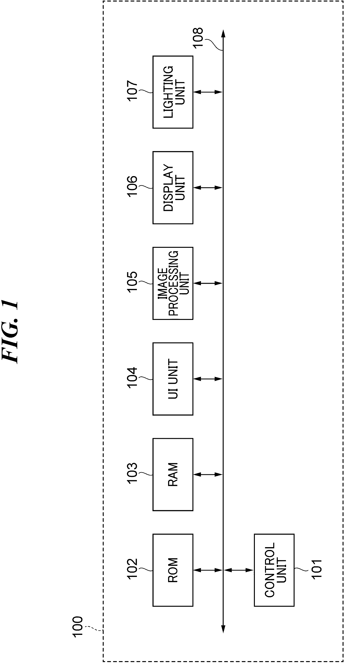
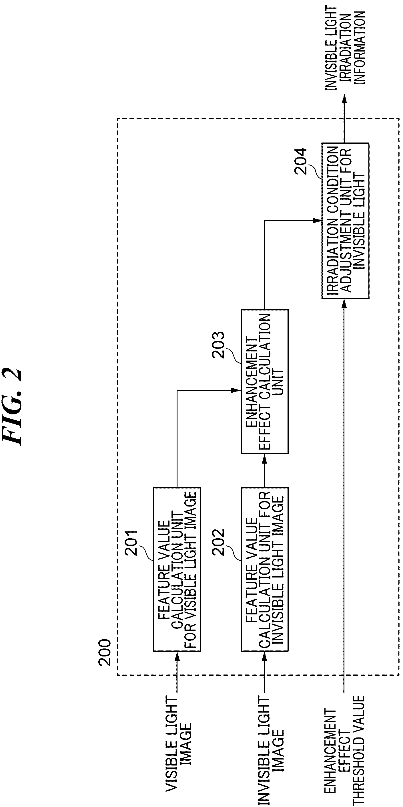
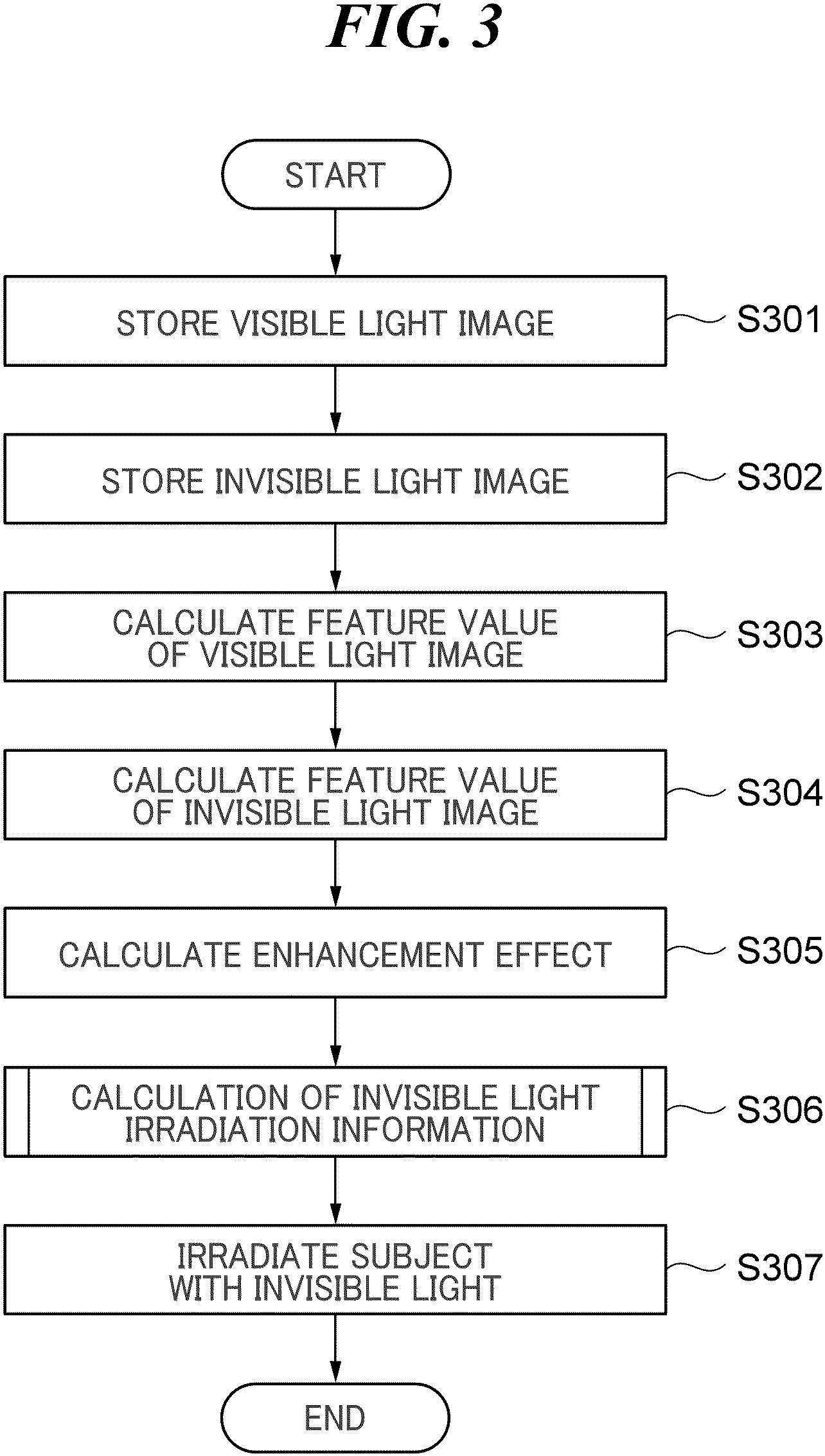
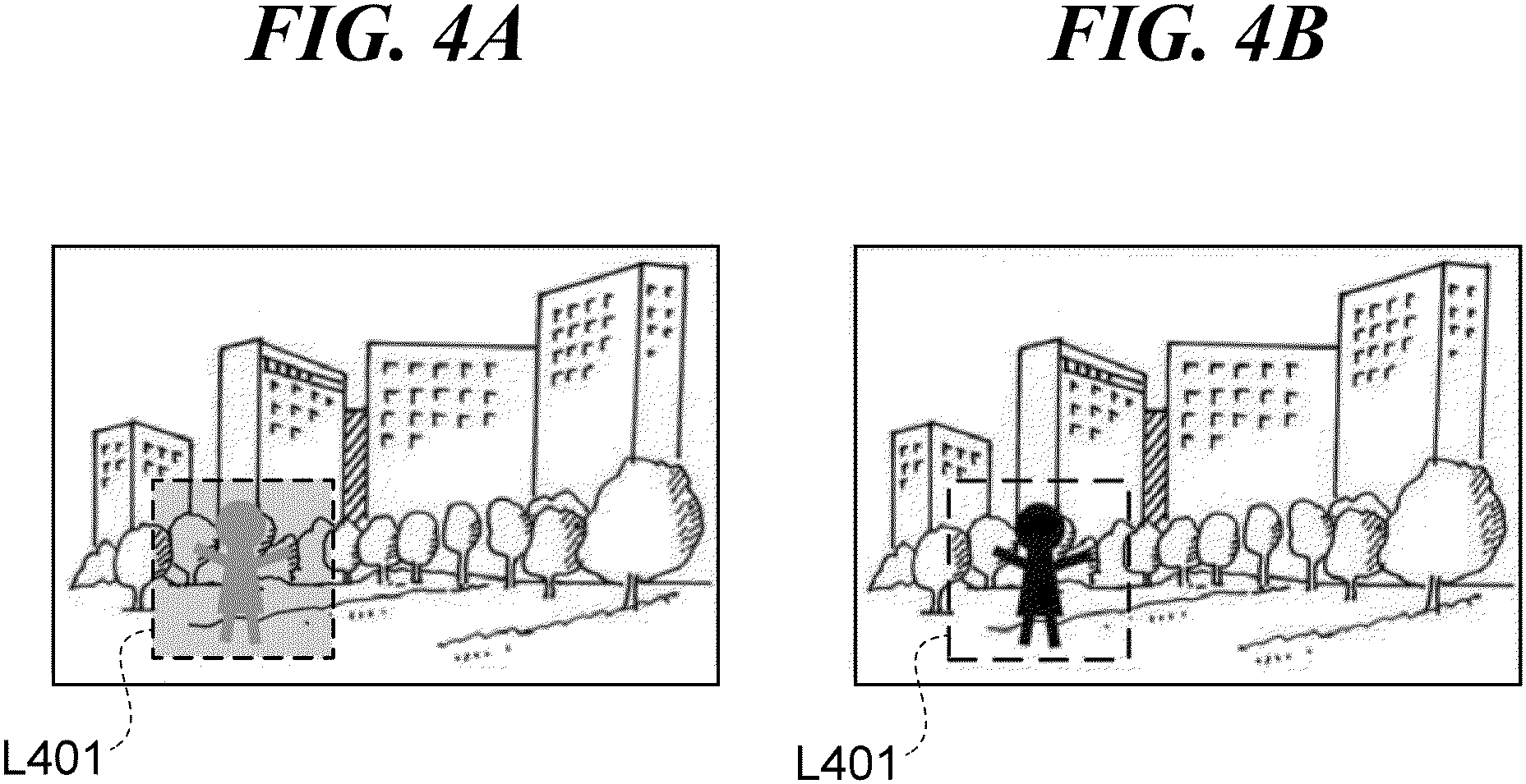
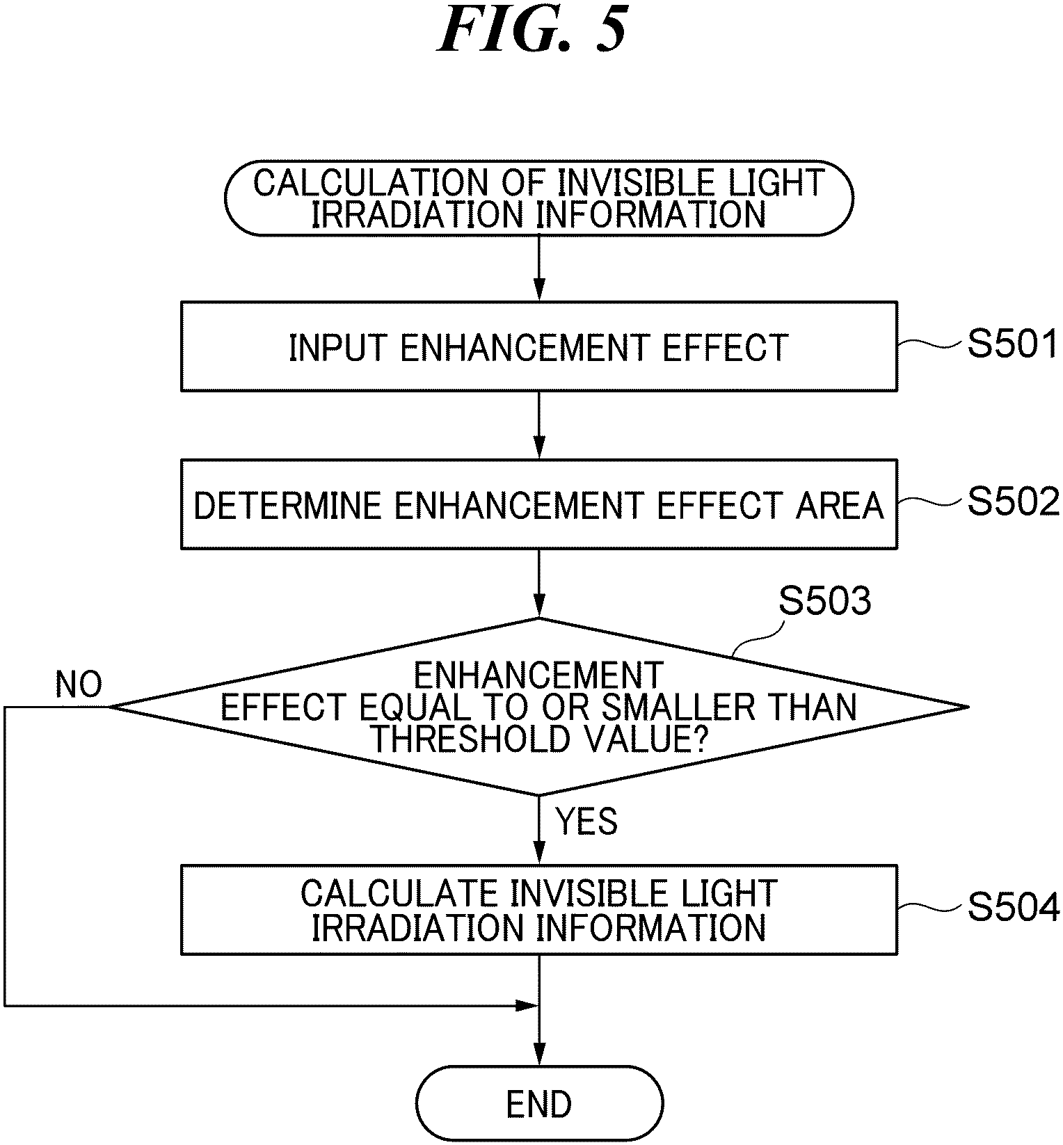
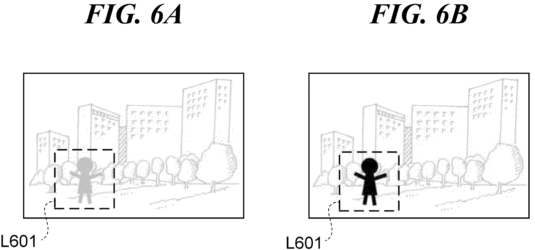
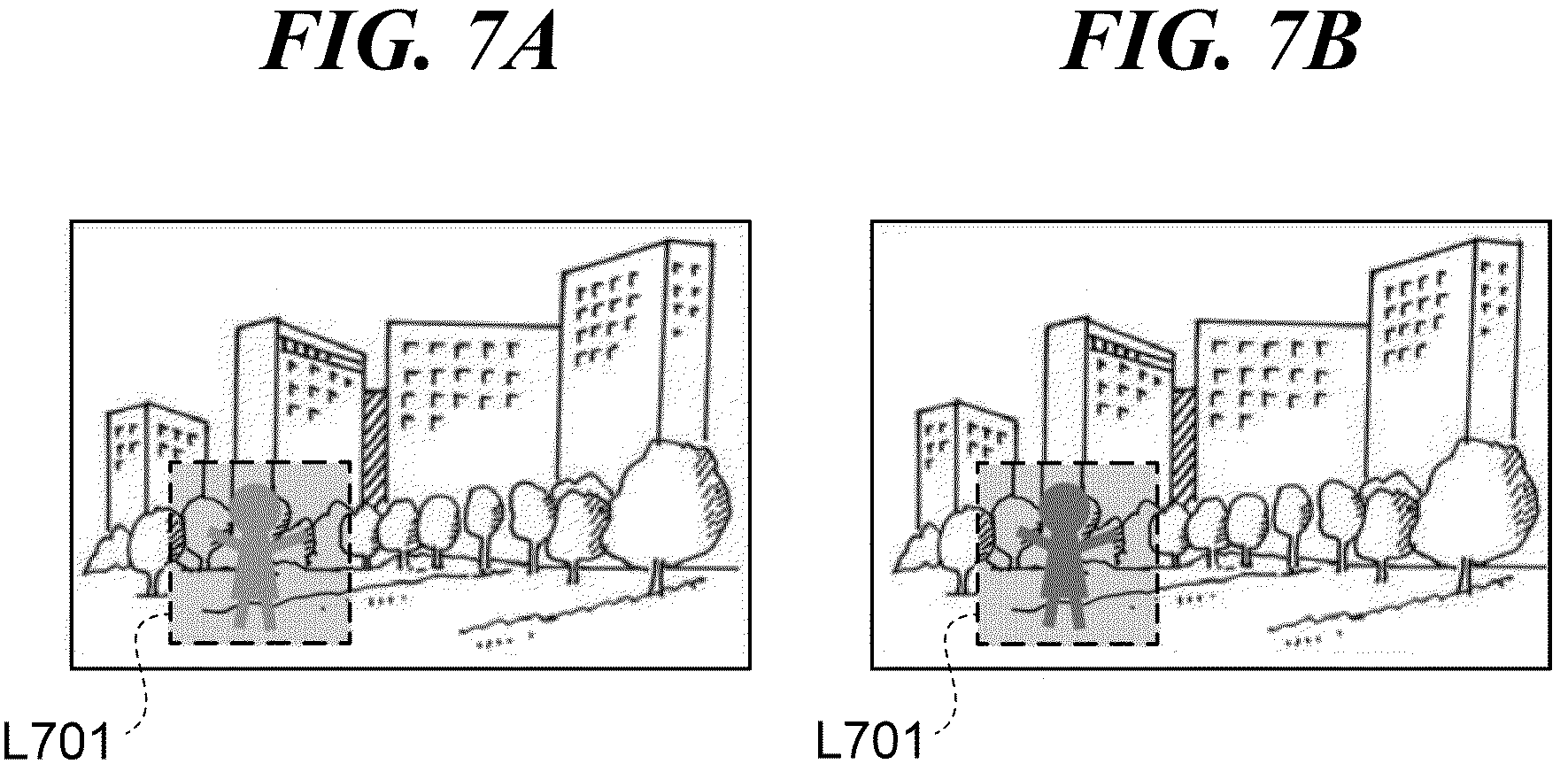
The present invention relates to image processing apparatuses, control methods for the image processing apparatuses, and storage media. Methods for improving the image quality of a visible light image with poor viewability because of haze or darkness are known, in which an invisible light image like an infrared image is used. To obtain a visible light image and an invisible light image in such methods, an image pickup device needs to capture light in a visible spectrum and light in an invisible spectrum with appropriate respective exposures. However, it is difficult to capture both a visible light image and an invisible light image with appropriate respective exposures, because, in many cases, there is a difference in intensity between visible light and invisible light, and a device operator is not allowed to set an exposure time and an aperture value independently for each of a visible light receiving element and an invisible light receiving element. Japanese Laid-Open Patent Publication (Kokai) No. 2015-126250 discloses a technique for capturing both a visible light image and an invisible light image with appropriate respective exposures, in which brightness levels of two images differing in wavelength band are evaluated, and the amount of irradiation of a subject with light provided by a lighting device having two light sources differing in wavelength band is controlled based on the evaluation result. However, the technique described in Japanese Laid-Open Patent Publication (Kokai) No. 2015-126250 can present a problem that the contrast and sense of resolution of a visible light image are not sufficiently improved, because the amount of irradiation of a subject with light provided by a lighting device having two light sources differing in wavelength band is controlled based on a result of an evaluation performed on the brightness levels of two images differing in wavelength band. The present invention provides image processing apparatuses capable of calculating appropriate irradiation conditions for invisible light so as to improve the image quality of a visible light image, control methods for the image processing apparatuses, and storage media. According to an aspect of the invention, an image processing apparatus includes a lighting unit configured to have one or more light sources which provide one or both of visible light and invisible light, and at least one processor and/or at least one circuit. The at least one processor and/or at least one circuit is configured to perform operations of: calculating a feature value of a visible light image obtained by shooting of a subject irradiated with visible light provided by the lighting unit; and calculating a feature value of an invisible light image obtained by shooting of the subject irradiated with invisible light provided by the lighting unit. The at least one processor and/or at least one circuit is configured to perform further operations of, based on the feature value of the visible light image and the feature value of the invisible light image, calculating irradiation conditions for the invisible light to be provided by the lighting unit. According to another aspect of the invention, a control method for an image processing apparatus equipped with a lighting unit having one or more light sources which provide one or both of visible light, includes calculating a feature value of a visible light image obtained by shooting of a subject irradiated with visible light provided by the lighting unit, and calculating a feature value of an invisible light image obtained by shooting of the subject irradiated with invisible light provided by the lighting unit. The control method further includes, based on the feature value of the visible light image and the feature value of the invisible light image, calculating irradiation conditions for the invisible light to be provided by the lighting unit. According to the present invention, appropriate irradiation conditions for invisible light are calculated so as to improve the image quality of a visible light image. Further features of the present invention will become apparent from the following description of exemplary embodiments with reference to the attached drawings. Embodiments of the present invention will now be described in detail below with reference to the accompanying drawings showing an embodiment thereof. In order to enhance the quality of a visible light image, such as gradation, contrast and sense of resolution, an image processing apparatus according to the present embodiment is configured to adjust irradiation conditions for invisible light based on feature values of a visible light image and an invisible light image obtained by shooting of the same subject at the same angle of view, and cause a lighting unit to project invisible light to irradiate the subject. It should be noted that the irradiation conditions for invisible light include the amount of irradiation with the invisible light (irradiation amount), a direction of the irradiation with the invisible light (irradiation direction), and an area of the irradiation with the invisible light (irradiation area). The control unit 101 is, for example, a CPU. The control unit 101 reads control programs for components of the image processing apparatus 100 from the ROM 102, loads the read control programs into the RAM 103, and executes them. In this way, the control unit 101 controls operation of the components of the image processing apparats 100. The ROM 102 is an electrically erasable programmable nonvolatile memory. The ROM 102 stores the control programs for the components of the image processing apparatus 100, parameters required for operation of the components, and so forth. The RAM 103 is a rewritable volatile memory. The RAM 103 is used as an area in which a program to be executed by the control unit 101 or the like is loaded, an area where data generated by operation of the components of the image processing apparatus 100 is temporarily stored, and so forth. The UI unit 104 is configured to receive user’s operations on the image processing apparatus 100. Examples of the UI unit 104 include a pointing device and a keyboard. Examples of the pointing device include a touch screen panel and a mouse. The image processing unit 105 is configured to perform image processing such as white balance, color interpolation, and gamma processing on image data stored in the RAM 103. The image processing unit 105 includes an irradiation condition calculation unit 200 for invisible light in The feature value calculation unit 201 for a visible light image is configured to calculate a feature value of a visible light image obtained by shooting of a subject irradiated with visible light provided by the lighting unit 107. Examples of the feature value of the visible light image include gradation information on the brightness component of the visible light image. To extract the gradation information, the feature value calculation unit 201 for a visible light image is configured to apply a bandpass filtering process, which allows through components in a specified band of frequencies, to the brightness component of the visible light image (for example, the intensity component or the I component in the ICtCp color space of the visible light image), thereby extracting information on an AC component of the brightness component of the visible light image (for example, an alternating-current component and its magnitude within the specified band of spatial frequencies in data obtained by extracting the brightness component from the visible light image), which indicates the gradation information. The feature value calculation unit 201 for a visible light image is configured to output the gradation information as the feature value of the visible light image to the enhancement effect calculation unit 203. The feature value calculation unit 202 for an invisible light image is configured to calculate a feature value of an invisible light image obtained by shooting of a subject irradiated with invisible light like infrared light provided by the lighting unit 107. Examples of the feature value of the invisible light image include gradation information on the invisible light image. To extract the gradation information, the feature value calculation unit 202 for an invisible light image is configured to apply a bandpass filtering process, which allows through components in a specified band of frequencies, to the invisible light image, thereby extracting information on an AC component of the invisible light image (for example, an alternating-current component and its magnitude within the specified band of spatial frequencies of the invisible light image), which indicates the gradation information. The feature value calculation unit 202 for an invisible light image is configured to output the gradation information as the feature value of the invisible light image to the enhancement effect calculation unit 203. The enhancement effect calculation unit 203 is configured to calculate an enhancement effect based on the feature value of the visible light image obtained from the feature value calculation unit 201 for a visible light image and the feature value of the invisible light image obtained from the feature value calculation unit 202 for an invisible light image. The enhancement effect means an effect of improving gradation, contrast, sense of resolution, and so forth of an image. Based on the enhancement effect calculated by the enhancement effect calculation unit 203 and optionally an enhancement effect threshold value, the irradiation condition adjustment unit 204 for invisible light is configured to calculate invisible light irradiation information that represents irradiation conditions for irradiation of a subject with invisible light to be provided by the lighting unit 107. Referring to Then, the control unit 101 causes the enhancement effect calculation unit 203 in the image processing unit 105 to calculate the enhancement effect based on the feature value of the visible light image and the feature value of the invisible light image (step S305). Referring to Then, the control unit 101 causes the image processing unit 105 to obtain invisible light irradiation information by carrying out a calculation process for the invisible light irradiation information, which will be described later with reference to Referring to Then, the irradiation condition adjustment unit 204 for invisible light determines whether or not the enhancement effect in the enhancement effect area determined in the step S502 is equal to or smaller than a threshold value (step S503). In the step S503, when the enhancement effect in the enhancement effect area determined in the step S502 is equal to or smaller than the threshold value (see, for example, For example, in an invisible light image shot with insufficient exposure, gradation information is insufficient, as illustrated in In the step S503, when the enhancement effect in the enhancement effect area determined in the step S502 is greater than the threshold value (see, for example, According to the embodiment described above, based on the feature value of a visible light image and the feature value of an invisible light image, the invisible light irradiation information representing the irradiation conditions for invisible light to be provided by the lighting unit 107 is calculated. It realizes optimized irradiation of a subject with the invisible light in shooting of an invisible light image for image quality improvement of a visible light image, which improves the quality of the visible light image. It should be noted that the control unit 101 may cause the lighting unit 107 to provide invisible light to irradiate a subject, using the irradiation amount, irradiation direction, and irradiation area that have been adjusted based on the invisible light irradiation information calculated in the step S504, obtain an invisible light image from an image pickup apparatus shooting of the irradiated subject, and based on the invisible light image, carry out the above-described invisible light control process again. In this case, when a desired enhancement effect cannot be achieved even by irradiation of the subject with the invisible light using the irradiation amount, irradiation direction, and irradiation area that have been adjusted based on the invisible light irradiation information, the irradiation amount, irradiation direction, and irradiation area for the invisible light are allowed to be adjusted again. In the embodiment described above, shooting conditions for shooting a subject may be adjusted based on the feature value of a visible light image, the feature value of an invisible light image, and the invisible light irradiation information. Examples of the shooting conditions include an ISO sensitivity, an f number, and a shutter speed. Thus, the image quality of a visible light image can be improved by optimization of the shooting conditions as well as the irradiation amount, irradiation direction, and irradiation area for invisible light. Moreover, in the embodiment described above, when the invisible light irradiation information includes information beyond the specifications of the lighting unit 107, the image processing apparatus 100 may issue a warning via an output device thereof in accordance with an instruction from the control unit 101. For example, when the invisible light irradiation information includes at least one of the following information: the irradiation amount beyond an upper limit to the amount of irradiation with light that the lighting unit 107 is capable of providing, an irradiation direction other than directions in which the lighting unit 107 is capable of providing light, and an irradiation area other than an area where the lighting unit 107 is capable of providing light, the control unit 101 causes the display unit 106 to display a warning notification. This informs a user that the adjustment of invisible light has reached its limits. While the present invention has been described with reference to exemplary embodiments, it is to be understood that the invention is not limited to the disclosed exemplary embodiments. The scope of the following claims is to be accorded the broadest interpretation so as to encompass all such modifications and equivalent structures and functions. Embodiment(s) of the present invention can also be realized by a computer of a system or apparatus that reads out and executes computer executable instructions (e.g., one or more programs) recorded on a storage medium (which may also be referred to more fully as a ‘non-transitory computer-readable storage medium’) to perform the functions of one or more of the above-described embodiment(s) and/or that includes one or more circuits (e.g., application specific integrated circuit (ASIC)) for performing the functions of one or more of the above-described embodiment(s), and by a method performed by the computer of the system or apparatus by, for example, reading out and executing the computer executable instructions from the storage medium to perform the functions of one or more of the above-described embodiment(s) and/or controlling the one or more circuits to perform the functions of one or more of the above-described embodiment(s). The computer may comprise one or more processors (e.g., central processing unit (CPU), micro processing unit (MPU)) and may include a network of separate computers or separate processors to read out and execute the computer executable instructions. The computer executable instructions may be provided to the computer, for example, from a network or the storage medium. The storage medium may include, for example, one or more of a hard disk, a random-access memory (RAM), a read only memory (ROM), a storage of distributed computing systems, an optical disk (such as a compact disc (CD), digital versatile disc (DVD), or Blu-ray Disc (BD)™), a flash memory device, a memory card, and the like. This application claims the benefit of Japanese Patent Application No. 2022-005874 filed on Jan. 18, 2022 which is hereby incorporated by reference wherein in its entirety. An image processing apparatus which is capable of calculating appropriate irradiation conditions for invisible light so as to improve the image quality of a visible light image. The image processing apparatus includes a lighting unit. A feature value of the visible light image obtained by shooting of a subject irradiated with visible light provided by the lighting unit is calculated. A feature value of invisible light image obtained by shooting of the subject irradiated with invisible light provided by the lighting unit is calculated. Irradiation conditions for the invisible light to be provided by the lighting unit are calculated based on the feature value of the visible light image and the feature value of the invisible light image. 1. An image processing apparatus comprising:
a lighting unit configured to have one or more light sources which provide one or both of visible light and invisible light; and at least one processor and/or at least one circuit configured to perform operations of:
calculating a feature value of a visible light image obtained by shooting of a subject irradiated with visible light provided by the lighting unit; calculating a feature value of an invisible light image obtained by shooting of the subject irradiated with invisible light provided by the lighting unit; and based on the feature value of the visible light image and the feature value of the invisible light image, calculating irradiation conditions for the invisible light to be provided by the lighting unit. 2. The image processing apparatus according to wherein the at least one processor and/or the at least one circuit is configured to perform further operations of, based on the feature value of the visible light image, the feature value of the invisible light image, and the irradiation conditions for the invisible light, adjusting shooting conditions under which the subject is shot. 3. The image processing apparatus according to wherein the irradiation conditions for the invisible light include an amount of irradiation with the invisible light, a direction of the irradiation with the invisible light, and an area of the irradiation with the invisible light. 4. The image processing apparatus according to wherein the at least one processor and/or the at least one circuit is configured to perform further operations of determining an area used for determination of the direction of the irradiation with the invisible light and the area of the irradiation with the invisible light. 5. The image processing apparatus according to wherein an area specified by the user via the user interface is determined as the area used for the determination. 6. The image processing apparatus according to wherein the feature value of the visible light image is gradation information on the visible light image, and an area in the visible light image where the gradation information is equal to or smaller than a predetermined value is determined as the area used for the determination. 7. The image processing apparatus according to wherein the at least one processor and/or the at least one circuit is configured to perform further operations of issuing a warning when the irradiation conditions for the invisible light are beyond specifications of the lighting unit. 8. A control method for an image processing apparatus equipped with a lighting unit having one or more light sources which provide one or both of visible light, the control method comprising:
calculating a feature value of a visible light image obtained by shooting of a subject irradiated with visible light provided by the lighting unit; calculating a feature value of an invisible light image obtained by shooting of the subject irradiated with invisible light provided by the lighting unit; and based on the feature value of the visible light image and the feature value of the invisible light image, calculating irradiation conditions for the invisible light to be provided by the lighting unit. 9. A non-transitory computer-readable storage medium storing a program for causing a computer to execute a control method for an image processing apparatus equipped with a lighting unit having one or more light sources which provide one or both of visible light,
the control method comprising:
calculating a feature value of a visible light image obtained by shooting of a subject irradiated with visible light provided by the lighting unit; calculating a feature value of an invisible light image obtained by shooting of the subject irradiated with invisible light provided by the lighting unit; and based on the feature value of the visible light image and the feature value of the invisible light image, calculating irradiation conditions for the invisible light to be provided by the lighting unit.BACKGROUND OF THE INVENTION
Field of the Invention
Description of the Related Art
SUMMARY OF THE INVENTION
BRIEF DESCRIPTION OF THE DRAWINGS
DESCRIPTION OF THE EMBODIMENTS
Other Embodiments