ADJUSTABLE GRIPPING DEVICE FOR THE TRANSPORTATION OR THE MACHINING OF PARTS OF DIFFERENT SHAPES
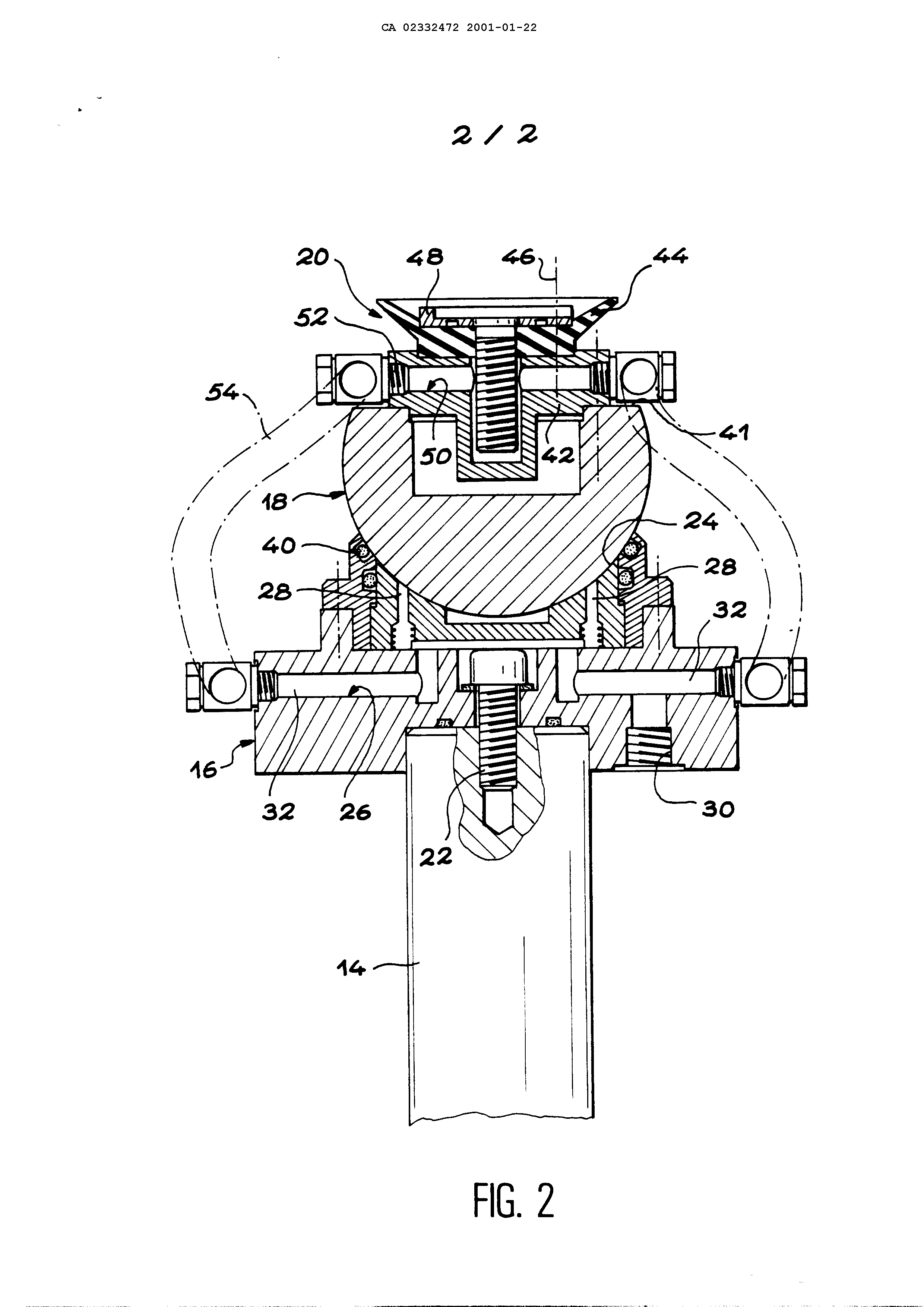
Connector for a windscreen for transportation or working of an irregularly shaped workpiece specification technical field a rotatable gripping device, adapted to permit machining or conveying a workpiece with any shape. Such a member may especially be used on a universal for gripping the one or more pieces during their processing or shipping. It allows in particular tantalum powder having very different geometries and more or less complex. State of the technique as shown especially the document FR's-a2 700,487, it is known transporting workpieces between various stations of an industrial plant, by means of a transportation pallet comprising a horizontal support plate having an interior chamber forming a supply of vacuum. The upper face of the support plate is pierced by holes arranged in a regular array and opening into the interior chamber. According to the shapes and sizes of workpieces to be conveyed, each of the holes receives either a gripper to suction cup, or a positioning member, or a shutter. Each gripping element comprises a vertical column bearing an adhesive gripper fixed at its top. A three-way valve allows SPs 17915, 69 GP of communication each suction cups or with the atmosphere, with either the vacuum in the interior chamber of the support plate, through a passage traveling in the post. Because the suction gripper are fixedly mounted at the ends of the studs, this type of conveying pallet can receive only flat pieces. Gold, the workpieces are rarely flat. In addition, geometric forms are often different, from one part to the other. The use of such a pallet would require permits use of specific gripping members for each room. This is unacceptable in an industrial process, due to the costs and time associated with it. The document FR's to-2 711,123 a conveyer and tipping for large parts. The apparatus comprises two platforms in respect to, equipped with a large number of posts provided at their ends with extendable suction gripper mounted on ball joints. In this system, each of the balls is held contacting a ball receptacle integral with open 1'extrémité of the post, by means of an elastic cord. In each of the suction cups, the vacuum grips is made through a central tube running in the corresponding post. This arrangement ensures the gripping parts of simple geometry, by spring deflection suction cups made possible by their mounting on balls. However, the overall deflection of each of the suction cups is limited to about SPs 17915, 69 The GP 60° (+ or - 30°), which is very insufficient for gripping the parts to complex geometries. On the basis of an arrangement comparable to that which is described in the document FR's to-2 711,123, the gripping members steerable existing do not allow a clearance overall skis or greater than 80° (+ ou - 40 degrees) because the vacuum supply is by a passage through the post and the support in which is received the ball. Exposed 1' present invention to provide a rotatable gripping device, whose original design allows it to obtain a clearance of at least 90° overall (+ ou - 45 degrees) of the suction cup for gripping the workpiece, thereby allowing the assembly of workpieces of complex geometries and liable to vary from one element to the other, without particular adaptation. According to the invention, this is achieved by means of a rotatable gripping device, comprising a ball, a ball receptacle open wherein said ball is pivotable, a means forming a suction cup carried by the ball outside of said ball seat, means for holding the ball in said ball seat, and a first passageway to 1' means inside of the suction cup and having at least one orifice formed on one of the ball and the means forming a suction cup, said port connected to a flexible tube, outside of the ball seat, and adapted to be connected to a source SP 17915, 69 GP of vacuum, characterized in that the means for holding the ball in said ball seat comprises a second passage extending through the ball seat, at least one first port of second through passageway between the ball and the ball seat. Because 1' vacuum supply of the suction cup is not done by a passage extending through the pillar which supports it, but instead from a flexible tube connected externally on the ball, it becomes possible to give it a range of movement substantially increased, generally of at least 90°. The member according to the invention is thus adapted to the gripping parts of complex geometries, different from one element to the other, without particular adaptation. Preferably, the flexible tube connecting the port of the first passage to a second port of the second lumen. In this case, the second passage preferably includes a third orifice, that can be connected to a source of compressed air, at the moment at which automatic orientation of the ball, and to said vacuum source during a phase of gripping a workpiece. With this arrangement, it becomes possible to precede gripping the workpiece a preliminary phase, during which the ball will automatically orient itself with respect to the facing surface of the workpiece, to present an optimal orientation with respect to said surface. Advantageously, the ball has a center of gravity offset opposite the means forming a suction cup, with respect to a geometric center of said ball. IN SP 17915, 69 The GP with this arrangement, the ball automatically returns to a neutral position horizontal when the facility is not in operation. Preferably, the means comprises a suction cup and a deformable thrust ring placed within the suction cup. The presence of the bearing retainer to better distribute stresses on the work created by the vacuum, thereby avoiding undesirable punching of the workpiece. In practice, the ball joint support comprises a spherical dome-shaped recess, in which is received the ball. The angle at the center of the cavity is at most equal to approximately 90°. In order to assure good overall distribution of forces, the deformable suction cup advantageously has a diameter substantially equal to the diameter of a circle circumscribing the cavity formed spherical. As it was already observed, the patella is advantageously capable of pivoting at least 90° in its support. Brief description of the drawings describe now, by way of non-limiting example, a preferred embodiment of the invention, by referring to the accompanying drawings, in which: figure 1 - is a side view, partial cross-section, which schematically depicts a portion of a table having a plurality of universal gripping members steerable according to the invention; and SP 17915, 69 The GP - 2 Figure is a sectional view illustrating an enlarged scale 1' drag of a steerable of Figure 1. Detailed description of a preferred embodiment of 1' described in Figure 1, is shown in a very schematic way a part of a table 10 universal, for transporting or P-machining workpieces. To accommodate this gripping, the table universal 10 carries, on its upper face, a number of grippers mounted on steerable 12 small columns 14. Only two gripping members 12 are orientable represented in Figure 1. in practice, the number of gripping members 12 implanted on the table universal depends in particular on the size of this table and the number of parts which is to be transported. In accordance with 1 'invention and as 1' illustrates more specifically in Figure 2, each of the gripper members steerable 12 includes a ball receptacle open 16, attached to the end of the post 14, and a ball 18 adapted to be rotated in the ball seat 16. Further, the portion which is located outside of the ball seat 16, each of the balls 18 carries a means forming a suction cup 20. The ball seat open 16 is in the form of a solid piece, multi-part. The patch is secured to the post 14 1'extrémité, for example by means of a screw 22. on its upper side, the ball seat open 16 includes SP 17915, 69 GP of cavity 24, cap-shaped, on which the ball 18 rests by gravity. The massive part forming the ball seat 16 is traversed internally by a passage 26. This passage 26 opens into the cavity 24 through one or more holes 28. It also opens to the underside of the ball seat 16 through an orifice and on the sides of this support 16 through at least one orifice 32 (two in the example shown). As shown schematically in Figure 1, a first end of a tube 34 is connected with the port 30. In the embodiment shown, the post 14 is expandable. The tube 34 is then a flexible tube, e.g. helically wound around the post 14. The opposite end of tube 34 may be connected at will either to a compressed air source 36, either to a vacuum source 38, as seen by schematically illustrated in Figure 1. The periphery of the cavity 24 formed spherical has a circular groove in which is housed a sealing ring 40. The gasket 40 is in sealing contact with the outer surface of the ball 18. it thus isolate normally 1'atmosphère outer 1' space between the cavity 24 and the ball 18, into which open the ports 28 of the passage 26. The ball 18 is in the form of a spherical part pitch on which is machined a flat 41 for securing the means forming a suction cup 20. More specifically, the means forming a suction cup 20 includes a base 42, 41 fixed to the land, for example by means of screws (not shown). A suction cup SPs 17915, 69 GP of deformable 44 is fixed to the base plate 42, for example by means of screws 46. Further, a rigid bearing ring 48 is mounted coaxially inside of the suction cup 44 and secured thereto, as well as to the base 42, by the screws 46. The base 42, the suction cup 44 and the bearing retainer 48 are traversed by a passage 50 whose one end terminates within the suction cup 44 and 48 of the bearing ring. The passage 50 further comprises at least one orifice 52 (two in the example shown) which opens to the outside, on the base 42, outside the cavity 24 formed in the ball seat 16. Each of the ports 32 of the passage 26 is connected to one of the orifices 52 of the passage 50 by a flexible tube 54, as shown schematically in Figure 1. The arrangement just described enables an angular deflection of at least about (+ ou - 45 degrees) 90° ball 18 with respect to the ball joint support 16. This feature is derived mainly through the evacuation of the suction cup 44 from the exterior of the ball seat 16, through the flexible tube 54. It follows from also because the spherical cap formed by the recess 24 has a center angle at most equal to approximately 90°. The clearance particularly important of the suction cup 44 enables continuous holding parts particularly complex shapes, which were not previously possible. Further, as shown in Figure 2, the diameter of the deformable suction cup 44 is substantially SPs 17915, 69 GP of equal to the diameter of the circle defining the cavity 24 formed spherical. This arrangement ensures good overall distribution of forces. In the embodiment shown, the massive part forming the ball 18 is partially recessed at the center of the land 41 carrying the means forming a suction cup 20. The center of gravity of the ball 18 is shifted away from the cup means 20, to the geometric center of the ball. This feature allows the suction cup 44 automatically flex horizontal neutral position when the handle member is at rest. Upon the implementation of such a rotatable gripping device, the post 14 is first brought to the correct height with respect to the workpiece. This may be done manually or automatically, for example using a digital control. Pressurized air is then injected through the tube 34 30 of the passage 26, thereby creating an air cushion between the ball 18 and the support 16 as well as between the part P and the suction cup 44. Automatic positioning is thus assured particularly efficiently and reliably. [...] is to be noted that, in an alternative advantageous embodiment of the invention, the control circuit of the means forming a suction cup 20 can be disconnected from the control circuit 18 opening out between the ball and the cavity 24. This allows, for example, blocked by the vacuum the ball 18 in a fixed position, while operating independently the evacuation or levitating the workpiece by SP 17915, 69 GP of suction cup. In this case, the adjustment of the orientation of the ball 18 may be performed either manually, either to 1' via a digital controller. IN SP 17915, 69 THE GP Rotatable gripping device for the transport or machining of an arbitrarily shaped part. A rotatable gripping device designed to be fitted on a universal table for the transport or machining of a part comprises a ball joint support (16), a ball joint (18) and a suction cup (44) supported by the ball joint. The vacuum in the suction cup (44) is created by the duct (50) connected through a flexible tube (54) directly to the ball joint (18)-suction cup (44) assembly, on the outside of the support (16). The resulting total angular movement of the suction cup (44) is thus at least 90° (+ or -45 °). 1. Directional body of gripping, including/understanding a kneecap, an open support of kneecap in which can swivel the aforementioned kneecap, an average formant suction cup carried by the kneecap outside the known as support of kneecap, of the means to maintain the kneecap in the aforementioned support of kneecap, and a first passage leading inside the average formant suction cup and comprising at least an opening formed on one among the kneecap and the average formant suction cup, the aforementioned opening being connected to a tube flexible, outside the support of kneecap, and ready to be connected to a source of vacuum, in which the means to maintain the kneecap in the aforementioned support of kneecap include/understand a second passage crossing the support of kneecap, at least a first opening of this second passage emerging between the kneecap and the support of kneecap. 2. Directional body of gripping according to the claim 1, in which the flexible tube connects the aforementioned opening of the first passage to a second opening of the second passage. 3. Directional body of gripping according to claim 2, in which the second passage includes/understands a third opening, ready to be connected successively to a source of compressed air, at the time of a phase of automatic orientation of the kneecap, and to the aforementioned source of vacuum, at the time of a phase of gripping of a part. 4. Directional body of gripping according to claim 1, in which the kneecap presents a centre of gravity shifted contrary to the average formant suction cup, compared to a geometrical center of the aforesaid the kneecap. 5. directional body of gripping according to the claim 1, in which the average formant suction cup includes/understands a deformable suction cup and a crown of support placed inside the suction cup. 6. Directional body of gripping according to claim 5, in which the aforementioned support of kneecap comprises a cavity in the shape of segment of a sphere, of angle in the center with most equal to approximately 90°. 7. Directional body of gripping according to according to the claim 6, in which the deformable suction cup has a diameter appreciably equal to the diameter of a circle delimiting the aforementioned cavity in the shape of segment of a sphere. 8. Directional body of gripping according to the claim 1, in which the kneecap is ready to swivel of at least 90° in the aforementioned support of kneecap.