Manual abrasive cutting-off machine for dividing rails
The invention refers to a Handtrennschleifmasehine for dividing rails in one to their longitudinal direction senkrechten level, with a clamping device 4s for fastening the machine to the Schienenkopf, whereby with the clamping device a first arm connected, second, approximately equal long poor in the free end of the first arm linked and the motor driven sharpening aggregate of the machine at the other end of the second arm around so a seem-parallel axle tiltable linked ist.
A hand cut-off grinding machine of this kind is admits (DE OS 2,512,705). For tightening at the rail the well-known hand cut-off grinding machine possesses a vice-similar clamping device, which is the rail head attachment bar and at that the first poor in with the help of a hinge pin or a joint around a seem-parallel axle is tiltable fastened. Unfavorable it is with this well-known hand cut-off grinding machine above all that with it two-hand control is essential. This makes more difficult the separation process completely substantially, since a movement of the sharpening aggregate and/or the separation grinding wheel planned at the sharpening aggregate is to be controlled around three axles, i.e. around the axle, around which the first arm is fastened to the clamping device tiltable, around the axle, around which the sharpening aggregate is relative to the second arm tiltable, as well as around the axle, around which the two arms are relatively to each other movable. Since separation grinding wheels connected with more highly rigidly and you are in such a manner arranged opposite that he is located in the enterprise perpendicularly to the rail bearing surface, and that both arms are more lãnger in each case than the diameter of the largest, into the machine applicable Trennschleifscheibe.
By the rigid connection of the first arm with the clamping device this arm in the position is to take up the largest part of the weight of the sharpening aggregate as well as the separation grinding wheel without here a support is necessary by the operator, whereby by the articulated connection of the two arms as well as by the articulated connection of the second arm with the sharpening aggregate the possibility remains at the same time, with the separation grinding wheel during the separation process the heating of the separation grinding wheel as small as possible too halten.
By the rigid connection of the first arm with the Kiemmvorrichtung further a fatigue danger of the operator is avoided. In addition an one-hand operation is thereby fundamental and/or - guidance of the hand cut-off grinding machine according to invention möglich.
Because the first arm stands with the enterprise perpendicularly to the rail bearing surface and/or rises up upward perpendicularly to the rail bearing surface, results to the oscillating second arm a pencil sharpener angle, with which effect that the force component of the weight of the sharpening aggregate working in feed direction produces at least a part of the contact pressure of the separation grinding wheel necessary for the Trennvor2 “course, which likewise leads to a discharge of the operator. Because the length first as well as the second arm is larger in each case than the diameter of the largest, in the machine used separation grinding wheel, NO a too large, in feed direction working and by the weight of the sharpening aggregate produced force component avoided, those the rocker movement necessary for the separation process and full splitting of a rail to make more difficult and the fatigue of the operator promote würde.
With the invention succeeded thus creating a hand cut-off grinding machine which using large, fast turning separation grinding wheels a whipping, sensitive manual feed with small energy expenditure ermöglicht.
The invention is more near described in the following on the basis the figures with a remark example. Show:
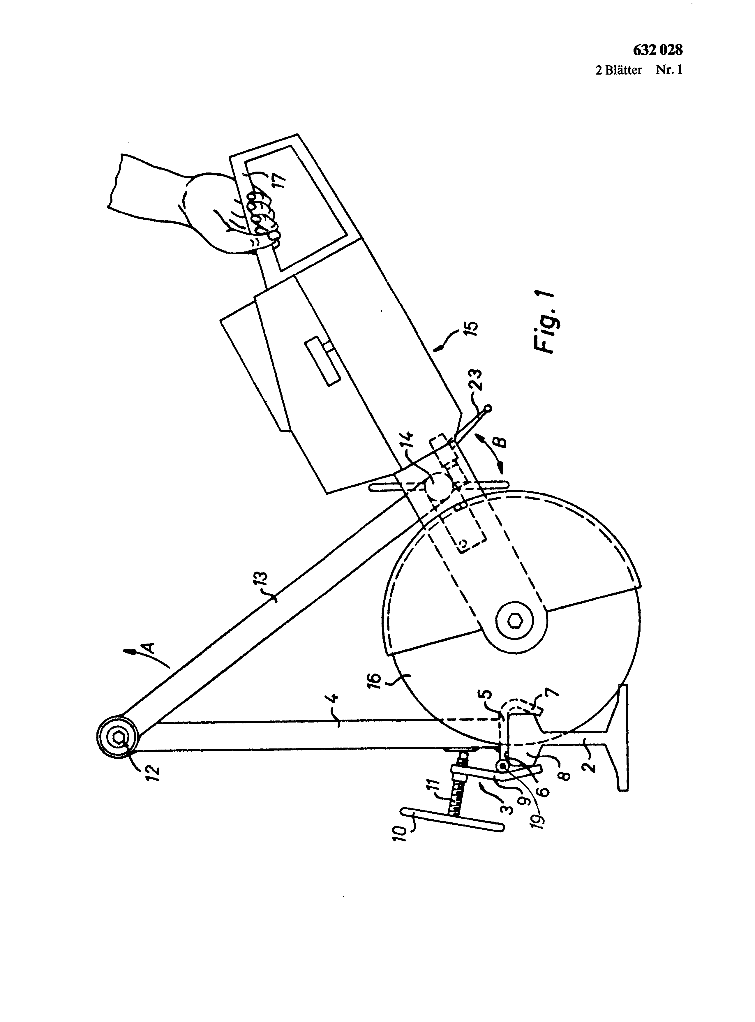
Fig. 1 a side view of a hand cut-off grinding machine in accordance with the invention; Fig. 2 an opinion of the hand cut-off grinding machine transverse to the rail longitudinal direction, with decreasing sharpening aggregate; Fig. 3 one to Fig. 1 similar opinion, however with decreasing sharpening aggregate:
Fig. 4 a scrap view of the hand cut-off grinding machine toward the arrow C of the Fig. 3, with fastened sharpening aggregate; The hand cut-off grinding machine serves for the production of “5 exactly right-angled cuts in rails, in particular in railway rails, with the help of a rotary separation grinding wheel (16).
On a rail, in particular railway rail (2), rigidly o 632,028 becomes fastened with the help of a clamping device (3) a first arm (4). This arm is down with a rail edition part (5) of the clamping device rigidly welded, whereby this rail edition part on the rail bearing surface (6) aufliegt.
The rail edition part (5) bent s possesses a thigh (7), the Schienenkopf (8) down partly covered. With the rail edition part (5) is a shim tiltable around an axle (19) (9) connected, which with the help of one at a screw pillar (! !) fastened handle (10) or a handwheel against lo the lower surface of the Schienenkopfes (8) to be pressed kann.
Thus the arm (4) with the rail (2) completely rigidly, but again solvable to connect, whereby the screw pillar (11) leaves itself against the arm (4) presses. At the upper end of the first arm (4) a joint (12) is, with which a second arm (13) is connected oscillating. This joint (12) is implemented that it is tiltable around at least 300°, preferably however a full revolution would drive out in such a way can. As from Fig. 2, become the two arms (4) and (13) come out over ball bearings of a continuous wave and/or axle (18) relatively to each other rotably gehalten.
For the joint (12) lying end of the arm (13) removes is over a joint (14) with the sharpening aggregate (15) and/or connected with the drive block of this sharpening aggregate, which drive block contains a driving motor of commercial construction, which over a transmission and links a separation grinding wheel (16) propels rotary. The drive block is from on sees well-known training. At the rear end of the drive block a handle (17) is, with the separation process one toward the double arrow B (Fig. 1) arranged Schwenkbzw.
Pendelbzw. Rocker movement around one to the wave (18) parallel and axle fixed by the joint (14) to be implemented can. Of the joints (12) and (14) formed axles as well as the axle (19) and the axis of rotation separate-sharpen disk (16) run parallel to each other and in longitudinal direction of the rail (2). The length of the arms (4) and (13) is substantially larger than the diameter of the separation grinding wheel (! 6) and at least the 11Afache amounts to, preferably for instance the 1 IAfache of the diameter of the largest separation grinding wheel (16), applicable into the machine.
There between the clamping device (3) and the drive block and/or the sharpening aggregate (of 15) only two joints (12) and (14) are present, can the separation grinding wheel (16) 4s sensitivly and surely be led. The joint (14) is provided with an adjustable brake. The arm (13) is clamped with the help of a thread mother between two shoulders (25) and (26). The drive block and/or the sharpening aggregate (15) is wegnehmbar for the relief of transport of the arm “o (13) befestigt.
Between the arm (13) and the sharpening aggregate (I 5) a solvable exists connection by a screw mounting (20) with thread, which is screwed in into a threaded bush (21). The Einscbrauben takes place itself by two facing hand levers (22), which drehfest over a wedge with the screw mounting (20) connected sind.
Thus the thread on the screw mounting (20) can screwed in into the interior fabric of the threaded bush (21) werden. by turn of the two hand levers (22)
a2 sheet designs of 632,028 2 pages No. 1 The transportable manual abrasive cutting-off machine is used for making cuts extending exactly at right angles to the longitudinal direction of the rail. A first arm (4) provided with a rail bearing (5) and clamping member (3) can be connected rigidly to the rail (2) and extends at right angles to the running surface (6) of the rail. A second arm (13) is secured on the first arm (4) in an articulated manner and bears a drive device (15) with a cutting-off wheel (16) in a pivotable arrangement, so that a tilting movement (arrow B) can be performed. Between the drive device (15) and the arm (13) there is a brake (23) whose action is adjustable. The lever arm (13) can be swivelled together with the drive unit (15), so that a cut can also be made from the other side of the rail, without the clamping members being touched. <IMAGE> i. Rail separator with a clamping device for solvable attachment the mechanism at the Schienenkopf, by which first, upward extending arm abragt, is articulated connected to containing drive block with separation grinding wheel at the other end of the second arm a second arm with the upper end of the first arm and is tiltable around a seem-parallel axle an engine, D A D u r C h g e k e n n z e i C h n e t that the first arm (4) in actually well-known way rigidly with the clamping device (3) is connected and both arms (4, 13) per a length has, which is larger than the diameter of the separation grinding wheel (16). 2. Rail separator according to requirement 1, D A D u r C h g e k e n n z e i C h n e t that the first arm (4) with on the Sehienenlanffläche a put onable rail on] ageteil (5) are welded or from only one piece exist and the first arm (4) right-angled to the rail bearing surface abragt and a length has, which has at least the ll/3 subject of the largest diameter of the separation grinding wheel (16).