ABRADING DEVICE HAVING A FRONT EXHAUST
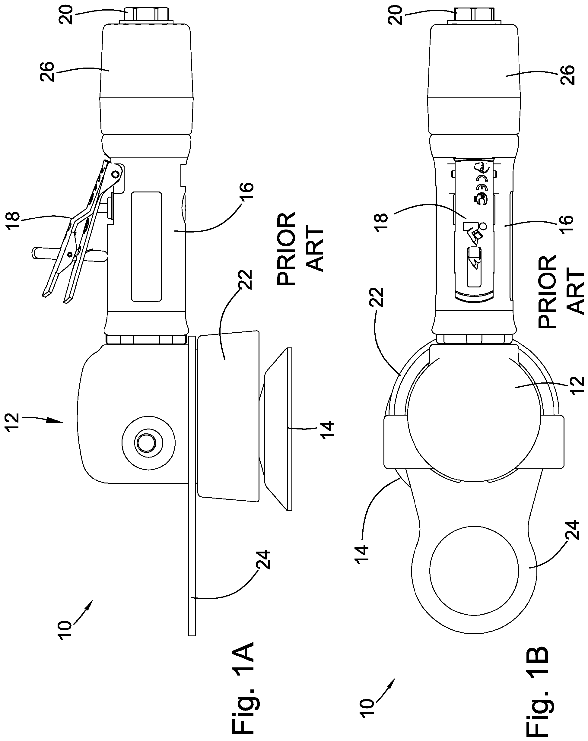
The invention broadly relates to abrading devices, more specifically to pneumatically-powered random orbital devices, and even more particularly to a pneumatically-powered random orbital buffer having a front exhaust. Random orbital buffing devices are well known in the art. They are used to polish and finish various surfaces without the drawbacks inherent to rotary-type buffing devices. For example, a random orbital buffer may be used to polish a coat of paint on a new automobile. Random orbital buffing devices are commonly pneumatically-powered. After being used to power the device, the compressed air or gas must be exhausted from the device. One problem common to pneumatic devices is that the exhausting air may produce a large amount of noise, which is undesirable for the user of the device. For example, abrading tool 10 is shown in Head 12 is affixed to handle portion 16, which includes trigger mechanism 18 for controlling the operation of tool 10. Port 20 is located at the back of the handle portion for coupling the tool to a pneumatic power source, such as a pressurized air tank. Shroud 22 is included to at least partially contain the drive means. Hang ring 24 may be included to provide a convenient means for storing the device when not in use, such as from a hook. The published European patent application Many devices incorporate mufflers to reduce the noise produced by the exhausting air. Traditionally, these mufflers increase the overall size of the device. To reduce the negative effects that this extra size has on the device's usability, these mufflers are commonly placed in or attached to the device's handle, since there is no room to accommodate a muffler in the head portion of the tool proximate the drive means. The channel from the coupling port (port 20) for the input air is frequently in the handle for the same reason, leading to a common design where the input and exhaust air lines are coaxial or parallel to each other in the handle of the device. That is, separate input and exhaust channels are both included in the handle. For example, muffler 26 is included at the rear of tool 10 to muffle the exhaust of the device. This embodiment results in the exhaust air being vented from the rear of the device, near the connector for the input air. This embodiment adds complexity to the device in the form of a second air line that runs the length of the device between the muffler and the outlet of the drive means. Additionally, a constant current of air is exhausted near the user while the device is in use. An alternative to this embodiment is included in some grinding devices, which involves venting the exhaust air from the front of the device, onto the abrading pad. Directly exhausting the drive means onto the abrading pad advantageously provides cooling of the pad. Additionally, two separate lines or channels are not required in the handle portion, reducing the complexity of the handle. Also, this eliminates the need to include a muffler, which, in addition to the lack of two channels in the handle, enables more design choices in handle shape and size. However, internal space is very limited in the head of these tools, resulting in front-exhaust tools which do not include mufflers. For grinding operations, muffling the exhaust is not a necessity, due to the inherent loudness of grinding. However, muffling is vital for buffing tools to reduce the noise of the tool. Thus, front-exhausting tools tend to be much louder than rear-exhausting tools. Some embodiments attempt to combine the benefits of the front-exhausting and rear-exhausting embodiments by piping the exhaust air from the muffler at the rear of the handle of the device with an exterior line to carry the exhaust back to the front of the device, where it is exhausted onto the pad. This embodiment adds the extra complexity and size for the exterior exhaust line. A final problem common to pneumatically-powered buffing devices, and buffing devices generally, is that heat created by the buffing action can damage the surface that is being polished. To prevent the build-up of excess heat, buffing devices are usually limited in speed, or users must operate the devices carefully to ensure particular portions of the surface are not overworked. These limitations reduce the effectiveness of the device, increasing the time needed to polish the surface. As can be derived from the variety of devices and methods directed at effectively exhausting pneumatically-powered buffing devices, many means have been contemplated to accomplish the desired end, The present invention provides an orbital abrading machine as defined in claim 1. The dependent claims define preferred embodiments of the present invention. These and other objects and advantages of the present invention will be readily appreciable from the following description of preferred embodiments of the invention and from the accompanying drawings and claims. The nature and mode of operation of the present invention will now be more fully described in the following detailed description of the invention taken with the accompanying drawing figures, in which:
At the outset, it should be appreciated that like drawing numbers on different drawing views identify identical, or functionally similar, structural elements of the invention. While the present invention is described with respect to what is presently considered to be the preferred aspects, it is to be understood that the invention as claimed is not limited to the disclosed aspects. Furthermore, it is understood that this invention is not limited to the particular methodology, materials and modifications described and as such may, of course, vary. It is also understood that the terminology used herein is for the purpose of describing particular aspects only, and is not intended to limit the scope of the present invention, which is limited only by the appended claims. Unless defined otherwise, all technical and scientific terms used herein have the same meaning as commonly understood to one of ordinary skill in the art to which this invention belongs. It should be appreciated that the term "device" is synonymous with terms such as "tool", "machine", etc., and such terms may be used interchangeably as appearing in the specification and claims. Additionally, the term "buffer," "buffing device," and the like may be used interchangeably. Furthermore, "abrasive pad" or "abrading pad" may be used to refer to any polishing, buffing, abrading, or other pad suitable for such orbital tools. Although any methods, devices or materials similar or equivalent to those described herein can be used in the practice or testing of the invention, the preferred methods, devices, and materials are now described. Referring now to the figures, In the shown embodiment, drive assembly 104 is arranged to enable head 100 to be used for random orbital abrading. For example, drive assembly 104 could generally refer to any suitable drive means for an abrading device, such as taught in the aforementioned '771 or '085 patents, which describe random orbital abrading devices. In the preferred embodiment, drive assembly 104 is regulated by a valve mechanism in a handle portion of a tool. For example, head 100 could affix to any suitable handle known in the art. As a specific example, head 100 could replace head 12 as shown in One embodiment of drive assembly 104 is shown in As shown generally in Muffling material 156 is included between the inner and outer shroud portions. In one embodiment, the muffling material is a strip of felt. By including muffling material 156 in the gap formed between the inner and outer shroud portions, the shroud effectively acts as a muffler for the buffer. Previously, as discussed above, muffler were included at the far opposite end of the handle from the buffer head, and the handle accordingly required two sealed channels so that the handle could both receive the pneumatic input and expel the exhaust. Thus, if head 100 is utilized, a muffler is not required at the opposite end of the buffing tool. For example, muffler 26 would not be required in tool 10 if head 12 were replaced with head 100. Additionally, since only one chamber is required in the handle, the arrangement of the handle can be greatly simplified. Front bearing plate 112 is shown in more detail in The assembly of head 100 can be best appreciated by referring again to Thus, it can be seen that a path can be traced throughout head 100 which enables the exhaust to be expelled directly on the abrasive pad. Specifically, air or some other operating fluid is supplied to head 100 via a port in a handle, such as port 20 in handle 16. The operating fluid then powers the rotor to rotate drive assembly 104 about shaft 118. The operating fluid is exhausted via outlets 172 into exhaust cavity 178 between cylinder 110 and the interior of housing 102. Cuts 162 and 164 enable the exhaust to flow out of exhaust cavity 178 and into shroud chamber 141. Specifically, in the shown embodiment, spacer 136 between lock ring 134 and plate 112 creates gap 138, which aligns with holes 152 in housing 102. Holes 152 align with outer and inner shroud portions 140 and 142 so that the exhaust enters shroud cavity 141. That is, the exhaust flows through the channel created by cuts 162 and 164 into gap 138, and from gap 138 through holes 152 into chamber 141. O-rings 144 and 148 seal above and below holes 152 to prevent leakage of the exhaust. The exhaust then exits shroud chamber 141 via holes 186 in the inner shroud portion and through slots 145 formed between projections 143 and the outer shroud portion. Accordingly, the exhaust is directly vented onto the abrasive pad for improved cooling of the pad during operation. By directly, it is meant that the exhaust is contained in the head and must only travel through the head, and not back through the handle. Advantageously, this enables increased buffing speed and buffer pad lifespan, decreased buffing time and a reduced occurrence of imperfections caused on the buffing surface due to overheating of the pad. The shown arrangement also reduces the required complexity of a handle for a tool using head 100, since the exhaust no longer needs to travel back through the handle, eliminating the need for a rear muffler ( Thus, it is seen that the objects of the present invention are efficiently obtained, although modifications and changes to the invention should be readily apparent to those having ordinary skill in the art, which modifications are limited only by the appended claim. It also is understood that the foregoing description is illustrative of the present invention and should not be considered as limiting. Therefore, other embodiments of the present invention are possible within the scope of the present invention as defined by the appended claims. An orbital abrading machine (10) comprising a head (100) comprising:
a housing (102); a shroud including inner and outer portions (140, 142), defining a shroud chamber (141) between said inner and outer portions (140, 142); a drive means (104) for driving an abrading pad (105), said drive means (104) at least partially enclosed by said housing (102) and said shroud, said drive means (104) having a pneumatically-powered rotor, wherein said drive means (104) produces an exhaust which is directly vented into said chamber (141) without leaving said head (100); an exhaust cavity (178) for receiving said exhaust from said drive means (104), wherein said exhaust cavity (178) is in pneumatic communication with said chamber (141) for enabling said exhaust to flow from said exhaust cavity (178) and into said chamber (141); wherein said chamber includes at least one opening for directing said exhaust toward said abrading pad (105) for cooling said pad (105) with said exhaust, the at least one opening constituted by at least one hole (186) in the inner shroud portion (142); wherein said inner and outer shroud portions (140, 142) are engaged against said housing (102) about an orifice (152) with a first seal (144) and a second seal (148), respectively; and wherein said orifice provides said pneumatic communication between said exhaust cavity and said chamber, said first and second seals for preventing leakage of said exhaust as said exhaust flows from said exhaust cavity through said orifice into said chamber. The orbital abrading machine (10) of claim 1, wherein said drive means (104) receives a pneumatic input, said pneumatic input sealed from said exhaust except for a path through said drive means (104). The orbital abrading machine (10) of claim 1 or 2, wherein muffling material (156) is contained within said chamber (141) for muffling said exhaust. The orbital abrading machine (10) of one of the claims 1 to 3, wherein said drive means (104) is secured at least partially within said housing (102) with a lock ring (134), wherein a spacer (136) is provided with said lock ring (134) for creating a gap (138), said gap (138) enabling pneumatic communication between said exhaust cavity (178) and said chamber (141). The orbital abrading machine (10) of one of the claims 1 to 4 wherein a handle (16) is secured to said head (100) and said handle (16) including a port (20) for coupling said abrading machine (10) to a source for powering said drive means (104). The orbital abrading machine (10) of one of the claims 1 to 5, wherein the orbital abrading machine (10) which has the head (100) is a random orbital buffer.FIELD OF THE INVENTION
BACKGROUND OF THE INVENTION
BRIEF SUMMARY OF THE INVENTION
BRIEF DESCRIPTION OF THE DRAWINGS
DETAILED DESCRIPTION OF THE INVENTION