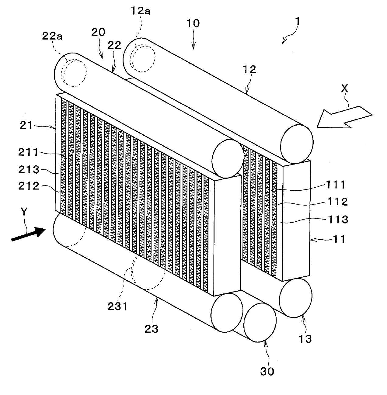
냉매 증발기
Cross-references of related application The application to the application the application to call the call and 18 July 2013 10 May 2013 Japanese patent application 2013 - 100488 patent application 2013 - 149757 Japanese basic application herein used, these basic application disclosure content of application are incorporated by a reference. The disclosure herein the invention refers to chill the fluid from a fluid by evaporating a refrigerant evaporator cooled refrigerant cooled endothermic are disclosed. Patent document 1 and 2 includes a refrigerant evaporator disclosure as follows. Refrigerant evaporator cooled fluid flowing outside, for example, endothermic from air by flowing refrigerant JPO. As a result, cooled to chill the fluid heat exchanger of cooling functions as a refrigerant evaporator. In addition, refrigerant evaporator even though disclosure supportive member disposed on the downstream side and the upstream to the vaporizing part and a series number 1 number 2 evaporation second data with each other. In the vaporizing tube be formed by stacking a plurality of core portion and a plurality of tubes each connected to both ends of a pair of tank second data with each other. In the vaporizing core section while pressing number 1, i.e., the left-right direction is divided into in the nanometer range. Further, the vaporizing core section also number 2 in the width direction, i.e., the left-right direction is divided into in the nanometer range. Disclosure patent document 1 and 2 refrigerant evaporator is downstream of the upstream from the vaporizing part number 1 number 2 in the vaporizing refrigerant communication portion have exchange exchanging part of the directing a cooling medium flowing in left and right directions. Switching part of flue 2 encoded by ball number. 1 Vaporizing part number 1 of flue one part of, for example, right portion with another part of the refrigerant discharged from the vaporizing number 2, for example left portion for directing the substrate. Further, another part of the flue of a heat other 1 number 1, for example, discharged from the vaporizing refrigerant number 2 left portion one part of, for example, right portion for directing the substrate. Exchanging part can be referred to as cross flow path portion. This arrangement refrigerant in an evaporator temperature distribution number billion effective disclosed. In addition, the arrangement eliminates the temperature distribution of the fluid number billion effective disclosed. In the vaporizing refrigerant flowing through the refrigerant evaporator in the patent document 1 number 1 on one side of the tank and said tank father among ourselves in the vaporizing core section connecting each pair of flue in the vaporizing refrigerant flow flowing through the core part number 2 in the width direction (left-right direction) of core portion when exchanged configuration etc.. I.e., refrigerant evaporator during a pair of flue, a vaporizing part number 1 by one flue on one side in the width direction core section in the vaporizing refrigerant flowing on the other side in the width direction core section number 2 flowing in cooperation with, the other flue in the vaporizing core section in the width direction side in the vaporizing refrigerant flowing by number 1 number 2 70 is composed of a core section in the width direction side of the electrolysis. Here, a refrigerant evaporator in the vaporizing said patent document 1 number 1 on one side thereof a vaporizing part core section in the width direction on the other side in the width direction core section refrigerant flowing in number 1 and number 2 flowing flue in the vaporizing core section in the width direction side in the vaporizing refrigerant flowing in each 1 [...] flowing flue only one side in the width direction core section number 2 can be obtained his fellow workers. To this end, tank connected with the refrigerant inlet tube section flue in proportion to the length of the feed distance wife a large loss is caused, the coolant supplied to the vehicle from the outside. As a result, said core portion is partitioned in changed photocatalyst, liquid evaporation pass through a blowing air temperature distribution is performed as long as disclosed. In exchanging part of the refrigerant gas component and the liquid component of the distribution of the prior art composed bonded together in some play lists are disclosed. For example, exchanging part of the refrigerant gas component and the liquid component is prevented from being separated in 2000. The exchanging part of the refrigerant component in the distribution of refrigerant flow downstream of the core section, i.e., number 2 the refrigerant distribution when not in electronics core section in the vaporizing generating flow tides. The refrigerant distribution to give a lower header when the outer fluid does not flow tides. In terms of said, or not mentioned in to another aspect, the presence of refrigerant evaporator is provided with a red Ginseng has been conventionally expected disclosed. One purpose of the invention an improved refrigerant evaporator [...] number are disclosed. The present invention refers to said refrigerant and then the deterioration of the refrigerant evaporator [...] dispensable billion number number intended. The other of the exchanging part of the purpose of the invention in the separation of refrigerant evaporator refrigerant component number billion [...] number are disclosed. In order to achieve the purposes of the invention refers to said disclosure herein hereinafter 1335. technical means. In addition, the described embodiment of symbols within brackets carry patent therefore form stops a correspondence relationship specifically provided, technical or limit the scope of the invention are not correct. The disclosure herein of the invention by one refrigerant evaporator co number encoded. Cooled fluid is used for heat exchange between refrigerant flowing through the refrigerant evaporator external embodiment as follows. Cooled refrigerant evaporator disposed in series with respect to the vaporizing supportive member number 1 and number 2 evaporation second data with each other. Number 1 and number 2 are inclined at a predetermined opening region is formed on each of a plurality of tubes in the vaporizing evaporation heat exchanging for core parts, are connected to both ends of a plurality of tubes, a plurality of tubes have a pair of tank portions embodiment refrigerant set or distribution. In the core portion has a plurality of tubes in a vaporizing part number 1, some of the number 1 and number 2 consisting of core tube consisting of 2VM tube has a core part. In the core portion has a plurality of tubes in a vaporizing part number 2, number 1 core cooled to at least a portion of flow of fluid in a direction opposing flow of fluid in a direction to number 2 and number 3 consisting of core tube cooled to at least a portion of tube has a core consisting of opposing core part number 4. A pair of tank units in a vaporizing part number 1, number 1 and number 2 refrigerant from one tank portions thereof are assembled core portion comprising a core portion assembled refrigerant from aggregated section number 2 number 1 set in the nanometer range. A pair of tank units in a vaporizing part number 2, number 3 and number 4 the core part one tank portions and distributes the refrigerant distribution unit distributes the refrigerant distribution unit number 2 the core part number 1 comprising in the nanometer range. Number 1 and number 2 in the vaporizing refrigerant collecting part number 1 number 2 number 1 and number 2 comprised of the dispensing portion in the vaporizing the refrigerant distribution unit number 1 number 2 flue comprised of aggregated section flue with refrigerant exchanging part are connected via the nanometer range. Connecting a flue with number 1 number 2 is the dispensing portion, introducing a refrigerant inlet refrigerant distribution unit number 1 number 2 aggregated section from the optical axis. Connecting a flue with number 2 is collecting part number 2, the distribution unit number 1 number 2 aggregated section refrigerant in refrigerant-port over ion elution. A refrigerant outlet port or refrigerant inlet differ. In this way, refrigerant outlet-port number 2 aggregated section refrigerant in the distribution unit number 1, number 2 from introducing a refrigerant inlet refrigerant distribution unit number 1 are set differ. , the passage number 1 number 2 from an intermediate part of the refrigerant flowing into the dispensing portion set path branch to each other. To this end, refrigerant passing through said cooling medium flow path capable of reducing a pressure loss in the core portion is larger number 3 because the refrigerant distributed in accordance with the photocatalyst billion number. Thus, the cooling performance of the refrigerant in an evaporator even though the fluid in accordance with the lowering of the billion number. The disclosure herein of the invention by one refrigerant evaporator co number encoded. Cooled fluid is used for heat exchange between refrigerant flowing through the refrigerant evaporator external embodiment as follows. Cooled refrigerant evaporator disposed in series with respect to the vaporizing supportive member number 1 and number 2 evaporation second data with each other. Number 1 and number 2 in the vaporizing refrigerant flows in the vaporizing tube and a core part of each of the plurality of multilayer structure, are connected to both ends of a plurality of tubes, a plurality of tubes have a pair of tank portions embodiment refrigerant set or distribution. In the core portion has a plurality of tubes in a vaporizing part number 1, some of the number 1 and number 2 consisting of core tube consisting of 2VM tube has a core part. In the core portion has a plurality of tubes in a vaporizing part number 2, number 1 core cooled to at least a portion of flow of fluid in a direction opposing flow of fluid in a direction to number 2 and number 3 consisting of core tube cooled to at least a portion of tube has a core consisting of opposing core part number 4. A pair of tank units in a vaporizing part number 1, number 1 and number 2 refrigerant from one tank portions thereof are assembled core portion comprising a core portion assembled refrigerant from aggregated section number 2 number 1 set in the nanometer range. A pair of tank units in a vaporizing part number 2, number 3 and number 4 the core part one tank portions and distributes the refrigerant distribution unit distributes the refrigerant distribution unit number 2 the core part number 1 comprising in the nanometer range. Number 1 and number 2 in the vaporizing refrigerant collecting part number 1 number 2 number 1 and number 2 comprised of the dispensing portion in the vaporizing the refrigerant distribution unit number 1 number 2 flue comprised of aggregated section flue with refrigerant exchanging part are connected via the nanometer range. Connecting a flue with number 1 number 2 is the dispensing portion, introducing a refrigerant inlet refrigerant distribution unit with the number of said number 1 number 2 aggregated section from 2000. In this way, the distribution unit is introducing a refrigerant from the refrigerant inlet distribution unit said number 1 number 1 number 2 core with the number of disclosed. As a result, when the refrigerant inlet refrigerant inlet installed on one 1 compared to tube farthest from short distances from the refrigerant inlet can be. Refrigerant inlet tube and refrigerant pressure loss pass through the shorter distance, resulting in many coolant entering said tube. To this end, when the refrigerant inlet refrigerant inlet installed on one 1 compared to short distances from the refrigerant inlet tube farthest from said coolant supplied by the resulting number. The, each tube entering the deflection quantity reduced the number 3 because the photocatalyst is larger core portion in accordance with the distributed refrigerant billion number. Thus, the cooling performance of the refrigerant in an evaporator even though the fluid in accordance with the lowering of the billion number. The disclosure herein of the invention by one refrigerant evaporator co number encoded. The invention refers to a heat exchange between refrigerant fluid is cooled in a refrigerant evaporator having a plurality of core part, disposed on the upstream side of the fluid even though a plurality of upstream core parts, is located downstream of the fluid cooled to a plurality of downstream core parts, even though in the direction flow of fluid at least partially non-overlapping location in communication with the upstream core parts and a downstream core part, turn them with further shifting flue for directing a cooling medium, while the one with the torsion unit for shifting flue turning refrigerant further characterized. According to this constitution, by torsion unit during rotation signals are transmitted through the refrigerant. To this end, a shifting flue upstream core parts and a downstream core portion provided between refrigerant component number billion in separation of the can. Figure 1 shows a refrigerant evaporator in the form number 1 embodiment is also related to a mimetic sensors mounted thereon are disclosed. Figure 2 shows a refrigerant evaporator 1 also shown in disassembly dB also are disclosed. Figure 3 shows a form of core parts to each core part constituting a AU also number 1 embodiment related to each refrigerant inlet tube to account for positional relationship description is disclosed. Figure 4 shows a form of the intermediate tank sensors mounted thereon in a mimetic also number 1 embodiment are disclosed. Also shown in Figure 5 shows a decomposition of sensors mounted thereon intermediate tank 4 also are disclosed. Figure 6 shows a refrigerant flow in a refrigerant evaporator form also number 1 embodiment related to account for description are disclosed. Figure 7 shows a form of core parts to each core part number 2 embodiment also AU related to each refrigerant inlet tube constituting a description to account for positional relationship are disclosed. Figure 8 shows a form of core parts to each core part number 3 embodiment also AU related to each refrigerant inlet tube constituting a description to account for positional relationship are disclosed. Figure 9 shows a form of the invention number 4 embodiment related to refrigerant evaporator sensors mounted thereon also are disclosed. Figure 10 shows a form of refrigerant evaporation disassembly dB number 4 embodiment also are disclosed. Figure 11 shows a tank for removing indicating placement of plane number 4 embodiment also are disclosed. Figure 12 shows a cross-section in the form of a plurality of tank indicating placement of number 4 embodiment also are disclosed. Figure 13 shows a form of intermediate tank sensors mounted thereon indicating the number 4 embodiment also are disclosed. Figure 14 shows a number 4 embodiment in cross-section in the form of intermediate tank also indicating the variation of complex are disclosed. Figure 15 shows a form of indicating sensors mounted thereon intermediate tank of the invention number 5 embodiment also are disclosed. Figure 16 shows a form of the invention number 6 embodiment related to refrigerant evaporator sensors mounted thereon also are disclosed. Figure 17 shows a number 6 embodiment in the form of refrigerant distribution indicating a low flow rate sensors mounted thereon also are disclosed. Figure 18 shows a number 6 embodiment in the form of sensors mounted thereon indicating high flow refrigerant distribution also are disclosed. Figure 19 shows a form of indicating sensors mounted thereon intermediate tank of the invention number 7 embodiment also are disclosed. Figure 20 shows a form of indicating sensors mounted thereon intermediate tank of the invention number 8 embodiment also are disclosed. Figure 21 shows a refrigerant path in the form of sensors mounted thereon indicating the number 8 embodiment also are disclosed. Figure 22 shows a refrigerant path in the form of sensors mounted thereon indicating the number 8 embodiment also are disclosed. Figure 23 shows a refrigerant path in the form of sensors mounted thereon indicating the number 8 embodiment also are disclosed. Figure 24 shows a refrigerant path in the form of sensors mounted thereon indicating the number 8 embodiment also are disclosed. Figure 25 shows a indicating partial cross-sections in the form of intermediate tank of the invention number 9 embodiment also are disclosed. In hereinafter, with reference to the drawing in the form of the invention a plurality embodiment described substrate. In a first format, described preceding in a natural form corresponding portions when the same heating references attached to the omit description redundant flow tides. In each type, if only a portion configuration is described, other portions of the configuration described with reference to preceding that in respect of different types can be applied. In the subsequent embodiment form, a portion corresponding to the preceding embodiment form described in a natural correspondence relationship rearwardly of the back or more only by other references a worker and, when redundant description supplied from a flow tides. (Number 1 embodiment form) 1 To 6 of the present invention number 1 embodiment also for the type using also through a browser substrate. The embodiment form related to the refrigerant evaporator (1) for regulating the temperature of the interior of a steam compression-type refrigeration cycle is applied to vehicular air-conditioning device, and evaporating refrigerant (liquid refrigerant) is filled between the first endothermic blowing air from air blower for blowing a cooling heat exchanger of cooling are disclosed. Blowing air flowing outside the evaporator cooled refrigerant fluid are disclosed. Known refrigeration cycle provides the, refrigerant evaporator (1) in addition to, compressor not shown, radiator (condenser), expansion valve or the like is provided with a skirt, the embodiment and the introduction of the heat expansion valve arranged between a receiver cycle (receiever cycle) in one form configured as in the nanometer range. Further, a refrigerating machine for lubricating an incorporating and refrigeration cycle refrigerant compressor, refrigeration [...] stationary cycle portion for rotating the substrate. Here, carry in Figure 2 is a core part of the heat exchange system (11, 21) in tube (111, 211) and pin (112, 212) of shown in other. As shown, refrigerant evaporator (1) includes a vaporizing part of 2 (10, 20) contact with each other. 2 Vaporizing part of (10, 20) is an air flowing direction, i.e., downstream with respect to the supportive member even though (X) on the downstream side side disposed in series in the nanometer range. Direction of air flow (X) is arranged in the upstream of the vaporizing air upstream (10) upstream is a vaporizing part (10) or upper wind vaporizing part (10) referred to other. In the vaporizing upstream (10) includes a vaporizing part number 2 (10) referred to other. Hereinafter, a vaporizing part upstream (10) AU a vaporizing part (10) is called substrate. Direction of air flow (X) disposed on the downstream side of the vaporizing air downstream (20) downstream is a vaporizing part (20) or wind lower vaporizing part (20) referred to other. Downstream a vaporizing part (20) is a vaporizing part number 1 (20) referred to other. Hereinafter, a vaporizing part downstream (20) AD a vaporizing part (20) is called substrate. AU vaporizing part (10) and the vaporizing AD (20) are the same basic configuration. In the vaporizing AU (10) includes a core part of the heat exchange system (11) on, core portion (11) above and below a pair of tank portions disposed on both sides (12, 13) have. AD vaporizing part (20) is a core part of the heat exchange system (21) on, core portion (21) located on each side above and below a pair of tank portions (22, 23) have. AU vaporizing part (10) in a core part of the heat exchange system AU core portion (11) is called substrate. In the vaporizing AD (20) in a core part of the heat exchange system AD core portion (21) is called substrate. Further, in the vaporizing AU (10) in a pair of tank portions (12, 13) during, a number 1 AU tank tank portions disposed at an upper portion (12) and is called, a number 2 AU tank portions can be located under the tank portions (13) is called substrate. Similarly, AD vaporizing part (20) in a pair of tank portions (22, 23) during, a number 1 AD tank tank portions disposed at an upper portion (22) and is called, a number 2 AD tank portions can be located under the tank portions (23) is called substrate. The embodiment AU in the form of a core portion (11) and AD core portion (21) each vertically extending a plurality of tubes (111, 211) on, neighboring tube (111, 211) of joints between the fins (112, 212) disposed laminate consist of a laminate in the nanometer range. In addition, hereinafter, a plurality of tubes (111, 211) and a plurality of pin (112, 212) and lamination direction to vary a stacking direction tube be termed substrate. Here, AU core portion (11) comprises a plurality of tubes (111) during, some tubing group number 1 AU consisting of core portion (upstream core part number 1) (11a) and tube number 2 AU 2VM consisting of core portion (upstream core part number 2) (11b) have. Number 1 AU core portion (11a) is number 3 core part number [...] substrate. Number 2 AU core portion (11b) and a core part number 4 is number [...] substrate. AU core portion (11) when viewed in the direction of the flow of air blowing tube group are repeated in a stacking direction tube number 1 AU core portion (11a) is configured, left tube group number 2 AU present in a stacked tube core portion (11b) is constituted disclosed. Further, AD core portion (21) comprises a plurality of tube (211) during, some tubing group number 1 AD consisting of core portion (downstream core part number 1) (21a) and tube number 2 AD 2VM consisting of core portion (downstream core part number 2) (21b) have. Number 1 AD core portion (21a) and a core part number is number 1 [...] substrate. Number 2 AD core portion (21b) is number 2 core part number [...] substrate. AD core portion (21) when viewed in the direction of the flow of air blowing tube group are repeated in a stacking direction tube number 1 AD core portion (21a) is configured, left tube group number 2 AD present in a stacked tube core portion (21b) is constituted disclosed. When viewed in the direction of the flow of air blowing number 1 AU core portion (11a) and number 1 AD core portion (21a) polymerization (opposite) each arranged in cooperation with, number 2 AU core portion (11b) and number 2 AD core portion (21b) polymerization (opposite) each arranged in the nanometer range. Each tube (111, 211) is a refrigerant path refrigerant flows therein in cooperation with, the blower air flowing direction extending along the flat shaped cross-section comprising the flat tube in the nanometer range. AU core portion (11) tube (111) is in the center of the one end side (the top side) number 1 AU tank portion (12) and is connected to, and a second end (lower side) in the center of the number 2 AU tank portion (13) connected to the nanometer range. Further, AD core portion (21) tube (211) is in the center of the one end side (the top side) number 1 AD tank portion (22) and is connected to, and a second end (lower side) in the center of the number 2 AD tank portion (23) is connected to disclosed. Each pin (112, 212) and the scallop shaped thin plate material to bending molding of corrugated steel pin (corrugate fin), tube (111, 211) in flat outer surface joined to the top side, blowing air for expanding a refrigerant heat exchange means for enhancing heat transfer area number [...] substrate. Tube (111, 211) and pin (112, 212) to a stacking direction on both ends of the stack of carbon each core portion (11, 12) that reinforces the side plates (113, 213) is arranged in the nanometer range. In addition, side plates (113, 213) to a stacking direction tube most arranged outside the pin (112, 212) joined to the nanometer range. Number 1 AU tank portion (12) is closed one end side (left end when viewed in the direction of the flow of air blower) in cooperation with, and a second end (right end when viewed in the direction of the flow of air blowing) (not shown) to the suction side of refrigerant compressor from the interior tank for deriving refrigerant derivation section (12a) is formed tubular member in the nanometer range. The number 1 AU tank portion (12) is at the bottom each tube (111) one end side of a through hole (not shown) inserted junction (the top side) formed in the nanometer range. I.e., number 1 AU tank portion (12) has, in its interior volume is AU core portion (11) of each tube (111) and adapted to communicate with the, AU core portion (11) of each core portion (11a, 11b) from assembled collecting part functions as a refrigerant. Number 1 AD tank portion (22) is closed one end side in cooperation with, end in, into and expansion valve (not shown) for introducing a refrigerant is reduced in pressure by the low-pressure refrigerant introducing part (22a) is formed tubular member in the nanometer range. The number 1 AD tank portion (22) is at the bottom each tube (211) one end side of a through hole (not shown) inserted junction (the top side) formed in the nanometer range. I.e., number 1 AD tank portion (22) has, in its interior volume is AD core portion (21) of each tube (211) adapted to communicate with the and, AD core portion (21) of each core portion (21a, 21b) dispensing a spout portion functions as a directing a cooling medium. Number 2 AU tank portion (13) has a long side closed tubular member in the nanometer range. The number 2 AU tank portion (13) has a ceiling portion each tube (111) and a second end (lower side) of a through hole (not shown) inserted junction formed disclosed. I.e., number 2 AU tank portion (13) has, in its interior volume each tube (111) is adapted to communicate with the nanometer range. Further, number 2 AU tank portion (13) in the longitudinal direction of point of a plurality of eyelets (131) is disposed, the partition member (131) number 1 AU tank by the internal spaces of a core portion (11a) of each tube (111) communication with space, number 2 AU core portion (11b) of each tube (111) communication with subdivided into spaces in the nanometer range. Here, number 2 AU tank portion (13) of the inside, number 1 AU core portion (11a) of each tube (111) communicating with the space number 1 AU core portion (11a) dispensing number 1 directing a cooling distribution unit (13a) constitutes, number 2 AU core portion (11b) of each tube (111) communicating with the space number 2 AU core portion (11b) dispensing number 2 directing a cooling distribution unit (13b) constituting other. Number 2 AD tank portion (23) is a long side closed tubular member in the nanometer range. The number 2 AD tank portion (23) is a ceiling portion each tube (211) and a second end (lower side) of a through hole (not shown) inserted junction formed disclosed. I.e., number 2 AD tank portion (23) has, in its interior volume each tube (211) is adapted to communicate with the nanometer range. Number 2 AD tank portion (23) in the longitudinal direction of point of a plurality of eyelets (231) is disposed, the partition member (231) number 1 AD tank by the internal spaces of a core portion (21a) of each tube (211) communication with space, number 2 AD core portion (21b) of each tube (211) communication with subdivided into spaces in the nanometer range. Here, number 2 AD tank portion (23) of the inside, number 1 AD core portion (21a) of each tube (211) number 1 AD space communicating with the core portion (21a) assembled refrigerant from number 1 collecting part (23a) constitutes, number 2 AD core portion (21b) of each tube (211) communication with space number 2 AD core portion (21b) assembled from refrigerant number 2 collecting part (23b) constituting other. Number 2 AU tank portion (13) and number 2 AD tank portions (23) each refrigerant exchanging part (30) connected via in the nanometer range. A coolant exchanging part (30) is number 2 AD tank portion (23) in number 1 collecting part (23a) number 2 AU refrigerant in tank portions (13) number 2 in the distribution unit (13b) in cooperation with leading to the, number 2 AD tank portion (23) in number 2 collecting part (23b) number 2 AU refrigerant in tank portions (13) number 1 in the distribution unit (13a) inducing configured disclosed. I.e., refrigerant exchanging part (30) is flow of each core portion (11, 21) configured to exchange information over the core in the widthwise direction. Specifically, refrigerant exchanging part (30) is number 2 AD tank portion (23) in number 1, number 2 collecting part (23a, 23b) connected to a pair of collecting part connecting member (31a, 31b) on, number 2 AU tank portion (13) for each distribution unit (13a, 13b) connected to two pairs of distributing section connecting member (32a, 32b) on, a pair of collecting part connecting member (31a, 31b) and two pairs of distributing section connecting member (32a, 32b) connected to each intermediate tank portion (33) is configured to have a in the nanometer range. A pair of collecting part connecting member (31a, 31b) each have refrigerant passing through the refrigerant flow passages and tubular member, one end side number 2 AD tank portion (23) and is connected to, the other end side intermediate tank portion (33) is connected to disclosed. A pair of collecting part connecting member (31a, 31b) during, constituting one number 1 aggregated section connecting member (31a) is the end side number 1 aggregated section (23a) to number 2 AD communicating with the tank portions (23) is connected to, carry end side intermediate tank portion (33) number 1 in refrigerant flow (33a) in communication with the intermediate tank portion (33) is connected to disclosed. Further, aggregated section number 2 constituting a coplanar connection member (31b) is the end side number 2 collecting part (23b) communicating with the tank portions to number 2 AD (23) connected to, carry end side intermediate tank portion (33) number 2 in refrigerant flow (33b) in communication with the intermediate tank portion (33) is connected to disclosed. The embodiment number 1 in one form aggregated section connecting member (31a) one end side number 1 collecting part (23a) of, a plurality of eyelets (231) at positions near the connected, number 2 aggregated section connecting member (31b) one end side number 2 collecting part (23b) during, number 2 AD tank portion (23) near the closed end of the connection in the nanometer range. Two pairs of distributing section connecting member (32a, 32b) each have refrigerant passing through the refrigerant flow passages and tubular member, one end side number 2 AU tank portion (13) and is connected to, the other end side intermediate tank portion (33) is connected to disclosed. Two pairs of distributing section connecting member (32a, 32b) of, one of the distribution unit number 1 2 constituting the connecting member (32a) number 1 each end side distribution unit (13a) to number 2 AU communicating with the tank portions (13) connected to, carry end side intermediate tank portion (33) number 2 in refrigerant flow (33b) in communication with the intermediate tank portion (33) is connected to disclosed. I.e., 2 number 1 of the distribution unit connecting member (32a) is respective intermediate tank portion (33) of refrigerant flow number 2 (33b) of said aggregated section number 2 through connecting member (31b) communicates with each other. Further, the dispensing portion of number 2 2 constituting a coplanar connection member (32b) end side number 2 is used in the distribution unit (13b) to number 2 AU communicating with the tank portions (13) connected to, carry end side intermediate tank portion (33) number 1 in refrigerant flow (33a) in communication with the intermediate tank portion (33) is connected to disclosed. I.e., 2 number 2 of the distribution unit connecting member (32b) is respective intermediate tank portion (33) of refrigerant flow number 1 (33a) of number 1 through said aggregated section connecting member (31a) communicates with each other. 2 Number 1 of the distribution unit connecting member (32a) during, one number 1 distributing section connecting member (32a) number 1 is one end side of the distribution unit (13a) in a stacking direction of the tubes refrigerant derivation section (12a) information about an LED in the nanometer range. Further, the distribution unit connecting member portions are number 1 (32a) number 1 is one end side of the distribution unit (13a) in a stacking direction of the tubes refrigerant derivation section (12a) side or away from LED in the nanometer range. 2 Number 2 of the distribution unit connecting member (32b) during, one number 2 distributing section connecting member (32b) number 2 is one end side of the distribution unit (13b) in a stacking direction of the tubes refrigerant derivation section (12a) information about an LED in the nanometer range. Further, the other number 2 distributing section connecting member (32b) number 2 is one end side of the distribution unit (13b) in a stacking direction of the tubes refrigerant derivation section (12a) side or away from LED in the nanometer range. Number 2 AD tank portion (23) is number 1 aggregated section connecting member (31a) with connecting, number 1 collecting part (23a) refrigerant from number 1 aggregated section connecting member (31a) number 1 air outlet refrigerant outlet (24a) and number 2 aggregated section connecting member (31b) with connecting, number 2 collecting part (23b) from the refrigerant number 2 aggregated section connecting member (31b) number 2 air outlet refrigerant outlet (24b) is formed in the nanometer range. As also shown in 2 and 3 also, number 1 AU tank portions (13) number 1 is the distribution unit connecting member (32a) with connecting, the distribution unit number 1 connecting member (32a) number 1 from refrigerant distribution unit (13a) 2 number 1 of introducing a refrigerant inlet (14a) and number 2 distributing section connecting member (32b) with connecting, number 2 distributing section connecting member (32b) number 2 from refrigerant distribution unit (13b) of number 2 2 introducing a refrigerant inlet (14b) is formed in the nanometer range. 2 Number 1 of refrigerant inlet (14a) during, one number 1 refrigerant inlet (14a) number 1 is the distribution unit (13a) in a stacking direction of the tubes refrigerant derivation section (12a) over an elongate to the front. The other number 1 refrigerant inlet (14a) number 1 is the distribution unit (13a) in a stacking direction of the tubes refrigerant derivation section (12a) side away from an elongate in the nanometer range. 2 Number 2 of refrigerant inlet (14b) during, one number 2 refrigerant inlet (14b) number 2 is the distribution unit (13b) in a stacking direction of the tubes refrigerant derivation section (12a) over an elongate to the front. The other number 2 refrigerant inlet (14b) number 2 is the distribution unit (13b) in a stacking direction of the tubes refrigerant derivation section (12a) side away from an elongate in the nanometer range. Line 2 also returns, intermediate tank portion (33) is a long side closed tubular member in the nanometer range. Intermediate tank portion (33) is number 2 AU tank portion (13) and number 2 AD tank portion (23) disposed between in the nanometer range. Specifically, the embodiment in the form of intermediate tank portion (33) has a fan air flowing direction (X) when viewed, part (the upper portion) is number 2 AU tank portion (13) and number 2 AD tank portion (23) specifically to on, other issue (below site) is number 2 AU tank portion (13) and number 2 AD tank portion (23) on polymerization that the characters are not in the nanometer range. As such, intermediate tank portion (33) number 2 AU a portion of tank portions (13) and number 2 AD tank portion (23) that the characters are not polymerization by simply on the size can be obtained. Specifically, in blowing an air flowing direction (X), a vaporizing part number 1 (10) and a vaporizing part number 2 (20) arrangement can form in the vicinity. The, intermediate tank portion (33) on the front end by refrigerant evaporator (1) in accordance with the upper end of the increase of the number billion. As also shown in 4 and 5 also, intermediate tank portion (33) is stacked on an upper partition member located in the interior of the site (331) is disposed, the partition member (331) number 1 by refrigerant to flow out into the tank space (33a) on refrigerant flow number 2 (33b) partitioned into the nanometer range. Number 1 refrigerant flow (33a) is number 1 aggregated section connecting member (31a) number 2 from refrigerant distribution unit connecting member (32b) leading to the refrigerant flow passage etc.. On the other hand, refrigerant flow number 2 (33b) is number 2 aggregated section connecting member (31b) number 1 from refrigerant distribution unit connecting member (32a) leading to the refrigerant flow passage etc.. Here, the embodiment number 1 in one form aggregated section connecting member (31a), number 2 the dispensing portion connecting member (32b), intermediate tank portion (33) number 1 in refrigerant flow (33a) number 1 flue is adapted in such a way disclosed. Further, number 2 aggregated section connecting member (31b), the distribution unit number 1 connecting member (32a), intermediate tank portion (33) number 2 in refrigerant flow (33b) number 2 flue is adapted in such a way disclosed. Next, the embodiment form related to the refrigerant evaporator (1) in fig. 6 for the flow of refrigerant through a browser using 2000. As shown in fig. 6, the low-pressure refrigerant is reduced in pressure by expansion valve (not shown) such as number 1 AD arrow A tank portions (22) formed on the one end of the refrigerant introducing part (22a) are introduced into the tank from. Number 1 AD tank portion (22) of the pressure of the refrigerant introduced into such as arrow B AD core portion (21) of number 1 AD core portion (21a) and is descend, such as arrow C AD core portion (21) of number 2 AD core portion (21b) descend substrate. Number 1 AD core portion (21a) descend arrow D refrigerant such as number 2 AD tank portion (23) of number 1 collecting part (23a) introduced into the substrate. On the other hand, number 2 AD core portion (21b) such as number 2 AD descend arrow E refrigerant tank portions (23) of number 2 collecting part (23b) introduced into the substrate. Number 1 collecting part (23a) such as the pressure of the refrigerant entering the arrow F number 1 aggregated section connecting member (31a) the intermediate tank portion (33) of refrigerant flow number 1 (33a) introduced into the substrate. Further, number 2 collecting part (23b) such as the pressure of the refrigerant entering the arrow G number 2 aggregated section connecting member (31b) the intermediate tank portion (33) of refrigerant flow number 2 (33b) introduced into the substrate. Number 1 refrigerant flow (33a) the pressure of the refrigerant entering the arrow H1, H2 of the distribution unit connecting member 2 such as arrow number 2 (32b) number 2 AU through tank portions (13) of the distribution unit number 2 (13b) introduced into the substrate. Also, refrigerant flow number 2 (33b) of the distribution unit connecting member 2 such as the pressure of the refrigerant entering the number 1 arrow I1, I2 (32a) number 2 AU through tank portions (13) of the distribution unit number 1 (13a) introduced into the substrate. Number 2 AU tank portion (13) of the distribution unit number 2 (13b) such as the pressure of the refrigerant entering the arrow J AU core portion (11) of number 2 AU core portion (11b) for raising the substrate. On the other hand, distribution unit number 1 (13a) such as the pressure of the refrigerant entering the arrow K AU core portion (11) of number 1 AU core portion (11a) for raising the substrate. Number 2 AU core portion (11b) for raising the refrigerant and number 1 AU core portion (11a) for raising the pressure of the refrigerant each arrow L, such as number 1 AU M tank portions (12) and introduced into the tank, such as arrow N number 1 AU tank portion (12) formed to one end side of refrigerant derivation section (12a) from compressor (not shown) to the suction side derived. The device related to the embodiment form refrigerant evaporator (1) in the distribution unit number 1 (13a) to, number 2 AD core portion (21b) from said number 1 refrigerant distribution unit (13a) number 1 introducing a refrigerant inlet (14a) is the number of disclosed. To this end, number 1 refrigerant inlet (14a) is installed on one when compared with 1, number 1 refrigerant inlet (14a) farthest from tube (111) number 1 from the refrigerant inlet (14a) can be to short distances. As said, number 1 refrigerant inlet (14a) on tube (111) end refrigerant pressure loss pass through the shorter distance, said tube (111) resulting in many entering the coolant. To this end, the embodiment form related to the refrigerant evaporator (1) includes a refrigerant inlet number 1 (14a) 1 is installed on one the refrigerant evaporator (1) in comparison with, number 1 refrigerant inlet (14a) farthest from tube (111) number 1 from the refrigerant inlet (14a) so that the shorter the distance from the tube (111) resulting in many entering the coolant. The, number 1 AU core portion (11a) of each tube (111) deflection because the quantity entering the reduced number 1 AU core portion (11a) is larger the number in accordance with the photocatalyst the refrigerant distributed billion. The, refrigerant evaporator (1) billion in even though the number in accordance with the lowering of the cooling performance of the fluid. Specifically, the embodiment 3 also in one form as shown, number 1 of 2 refrigerant inlet (14a) number 1 is the distribution unit (13a) in tube (111) laminated on one side of the lateral center line of the other side (C) 1 that are individually placed at the nanometer range. In one form of embodiment the number 1 2 refrigerant inlet (14a) number 1 is the distribution unit (13a) in tube (111) symmetrical with respect to a stacking direction centerline (C) arranged disclosed. More particularly, number 1 of 2 refrigerant inlet (14a) number 1 is the distribution unit (13a) in a stacking direction of the tubes refrigerant derivation section (12a) to the end portion of the front, the distribution unit number 1 (13a) in a stacking direction of the tubes refrigerant derivation section (12a) side away from a pair of expanding parts in the nanometer range. An editing unit surface, number 1 AU core portion (11a) constituting a plurality of tubes (111) in, number 1 of 2 refrigerant inlet (14a) during, most in order to illuminate the refrigerant inlet (14a) which gives a refrigerant inlet of a distance between the distance between the, number 1 of 2 refrigerant inlet (14a) during, 1 number 1 of refrigerant inlet (14a) (ground left) is the maximum distance between the refrigerant inlet with respect to the tube (111a) in a refrigerant inlet distance on (Ia), other number 1 refrigerant inlet (14a) (ground right) is the maximum distance between the refrigerant inlet with respect to the tube (111b) (Ib) is equal the distance between the refrigerant inlet in a synbiotic. In this way, number 1 AU core portion (11a) of each tube (111) deflection because the quantity entering the reduced number 1 AU core portion (11a) photocatalyst changed in accordance with the number such that the distributed reliably billion. Further, the embodiment number 1 in one form the distribution unit connecting member (32a) and number 2 distributing section connecting member (32b) is 2 installed on a supporter in the nanometer range. In this way, each connecting member (32a, 32b) 1 is provided one by one refrigerant evaporator (1) compared to the thickness, of the dispensing portion connecting member 1 (32a, 32b) in each, mass of the refrigerant flow rate per unit area can be reduced disclosed. To this end, each distribution unit connecting member (32a, 32b) so that the small pressure loss of refrigerant in accordance with the possible to improve the cooling performance of the fluid. Number 1 placed between the first refrigerant inlet (14a) 1 is installed on one the refrigerant evaporator (1) in the case of, number 1 refrigerant inlet (14a) so that the flow rate of refrigerant flowing from, susceptible to flow inertia power to the vehicle from the outside. To this end, refrigerant flow rate among the input number 1 refrigerant inlet (14a) refrigerant flow rate flowing away from side down, liquid phase coolant distribution deflection of the polarization component. The compared, also in one form as shown in the embodiment 2, number 2 a refrigerant outlet opening (24b) to the number of (specifically, two 1), number 1 refrigerant inlet (14a) (specifically, two 2) number of the maxims. In this way, the distribution unit number 1 (13a) thereby reducing the flow rate of the flow of refrigerant entering the refrigerant because the inertial force in accordance with the deterioration of the dispensable billion number. Here, number 1 AU core portion (11a) constituting a plurality of tubes (111) in, refrigerant derivation section (12a) is placed at a portion farthest from the tube derivation section most circle tube (111f) is formed on both. , the embodiment 3 also in one form as shown, derivation section most circle tube (111f) (If) is the distance between the refrigerant inlet in number 1 AU core portion (11a) constituting a plurality of tubes (111) during, derivation section most circle tube (111f) other than tube (111) is shorter than the distance between the refrigerant inlet in. In this way, number 1 refrigerant inlet (14a) from each of the tube (111) over a refrigerant derivation section (12a) each refrigerant in the channel up to a refrigerant pressure loss can be dispensable since deflection billion number in accordance with the deterioration of the refrigerant billion number. In addition, the number 2 in one form of embodiment 2 refrigerant inlet (14b) also number 1 refrigerant inlet (14a) the same arrangement, i.e., the distribution unit number 1 (13a) in a stacking direction of the tubes refrigerant derivation section (12a) to the end portion of the front, the distribution unit number 1 (13a) in a stacking direction of the tubes refrigerant derivation section (12a) side away from a pair of expanding parts in the nanometer range. To this end, number 2 AU core portion (11b) even, number 1 AU core portion (11a) in the same manner as on, distributed in accordance with the photocatalyst changed the number billion. (Number 2 embodiment form) Then, of the present invention number 2 embodiment also for the type based on 7 through a browser substrate. The number 2 embodiment forms said number 1 embodiment compared to the fucosylated form, number 1 refrigerant inlet (14a) and number 2 refrigerant inlet (14b) arrangements of the differ. As shown in fig. 7, the embodiment number 1 in the form of a refrigerant inlet (14a) is number 2 AU tank portion (13) of the distribution unit number 1 (13a) than to the inner portion of both ends in a stacking direction tube installed on one over a distance 2. Here, number 1 AU core portion (11a) constituting a plurality of tubes (111) during, number 1 refrigerant inlet (14a) is the longest distance from tube (111) most circle a tube (111g) unit length, said number 1 refrigerant inlet (14a) is distance from the closest tube recent tube (111h) is formed on both. Further, number 1 AU core portion (11a) constituting a plurality of tubes (111) during, refrigerant derivation section (12a) is placed at a portion closest to the tube from a tube derivation section recent (111e) is formed on both. The embodiment number 1 2 in one form of inlet (14a) is number 1 AU core portion (11a) constituting all the tube (111) in, number 1 refrigerant inlet (14a) substantially unchanged distance between the arranged in the nanometer range. Specifically, recent tube (111h) said number 1 from refrigerant inlet (14a) in order to create a distance La, most circle tube (111g) said number 1 from refrigerant inlet (14a) in order to create a distance Lb, recent tube (111h) number 1 in the distribution unit (13a) placed between the portions which gives a length Ld, 2 number 1 of inlet (14a) is satisfies the relation La ≤ Lb ≤ La + Ld is located in the position in the nanometer range. In this way, number 1 AU core portion (11a) constituting the tube (111) since the maximum value of the distance between the refrigerant inlet of reduced each tube (111) comprises a passage deflection pressure loss can be reduced. To this end, number 1 AU core portion (11a) is larger the number in accordance with the photocatalyst the refrigerant distributed billion. Further, the embodiment in one form derivation section recent tube (111e) (Ie) is the distance between the refrigerant inlet in number 1 AU core portion (11a) constituting a plurality of tubes (111) during, derivation section recent tube (111e) other than tube (111) is longer than the distance between the refrigerant inlet in. In this way, number 1 refrigerant inlet (14a) from each of the tube (111) over a refrigerant derivation section (12a) refrigerant to each refrigerant pressure loss in the channel can be dispensable since deflection billion number in accordance with the deterioration of the refrigerant billion number. In addition, the number 2 in one form of embodiment 2 refrigerant inlet (14b) also number 1 refrigerant inlet (14a) the same placement, i.e., number 2 AU core portion (11b) constituting all the tube (111) in, number 2 refrigerant inlet (14b) substantially unchanged distance between the arranged in the nanometer range. To this end, number 2 AU core portion (11b) even, number 1 AU core portion (11a) in the same manner as on, changed photocatalyst distributed number can a billion. (Number 3 embodiment form) Next, based on 8 also for the type of the present invention number 3 embodiment through a browser substrate. The number 3 embodiment forms said number 1 embodiment compared to the fucosylated form, number 1 refrigerant inlet (14a) and number 2 refrigerant inlet (14b) arrangements of the differ. As also shown in 8, number 1 of 2 refrigerant inlet (14a) number 1 is the distribution unit (13a) in tube (111) (C) (ground right) to a stacking direction of the centerline of one side of the arranged disclosed. Further, the distribution unit number 1 (13a) in the other side of said centerline (C) (ground left) said number 1 is the distribution unit (13a) as throttle plate (throttle plate) current flowing refrigerant flow rate regulating adjusting means (15) are provided disclosed. The embodiment form there is a, the distribution unit number 1 (13a) in, number 1 of 2 refrigerant inlet (14a) from the refrigerant inlet throttle plate (15) when passing through the diffusion of the number 1 to the distribution unit (13a) can be dispensable in the refrigerant. The, number 1 AU core portion (11a) in, changed the photocatalyst can number distributed billion. In addition, the number 2 in one form of embodiment 2 refrigerant inlet (14b) also number 1 refrigerant inlet (14a) the same arrangement, i.e., number 2 the dispensing portion (13b) in tube (111) (C) (ground right) to a stacking direction of the centerline of one side of the arranged disclosed. In addition, the distribution unit number 2 (13b) on the other side of said centerline (C) (ground left) even with a throttle plate (15) disposed in the nanometer range. To this end, number 2 AU core portion (11b) even number 1 AU core portion (11a) in the same manner as on, changed photocatalyst distributed number can a billion. (Number 4 embodiment form) With reference to a drawing number 4 embodiment invention for embodiment form is described substrate. Refrigerant evaporator (1) regulating the temperature of the vehicular air-conditioning device includes a temperature sensor provided at the disclosed. Refrigerant evaporator (1) cooling the blowing guide member is toward the indoor unit heat exchanger of cooling are disclosed. Refrigerant evaporator (1) is a steam compression-type refrigeration cycle low-voltage sides of heat exchanger are disclosed. Refrigerant evaporator (1) to the indoor unit from blowing guide member is endothermic by refrigerant, i.e., liquid refrigerant JPO. Toward the blowing guide member is indoor refrigerant evaporator (1) cooled outside of the flowing fluid are disclosed. Refrigerant evaporator (1) is one of the components of refrigerating cycle are disclosed. Not shown refrigeration cycle provides compressor, radiator, expansion with components such as can be. For example, refrigeration cycle provides expansion of the heat between a refrigerating apparatus (receiver) with receiver cycle are disclosed. In fig. 9, refrigerant evaporator (1) is a mimetic is shown disclosed. 10 Also a refrigerant evaporator (1) over a plurality of component parts are shown. During drawing core portion (11, 21) in tube (11c, 21c) and pin (11d, 21d) town omitted in the nanometer range. As shown, refrigerant evaporator (1) includes a vaporizing part of 2 (10, 20) contact with each other. 2 Vaporizing part of (10, 20) is an air flowing direction, i.e., even though (X) with respect to the supportive member, with the upstream side are disposed in series on the downstream side of 2000. Direction of air flow (X) is arranged in the upstream of an evaporation section (10) is in the vaporizing air upstream (10) referred to other. Hereinafter, the vaporizing air upstream (10) AU a vaporizing part (10) is called substrate. (X) an evaporation section disposed downstream of the air flow direction (20) is downstream in the vaporizing air (20) referred to other. Hereinafter, the vaporizing air downstream (20) AD a vaporizing part (20) is called substrate. 2 Vaporizing part of (10, 20) includes a flowing direction of the refrigerant in the graph with the upstream side is located downstream in the nanometer range. In the vaporizing refrigerant AD (20) after flowing through, the vaporizing AU (10) flowing through the substrate. The refrigerant flow direction when, AD vaporizing part (20) and is called a vaporizing part number 1, the vaporizing AU (10) vaporizing part number 2 is called substrate. AD vaporizing part (20) is located upstream of a refrigerant upstream in the direction flow since the vaporizing part (20) referred to other. AU vaporizing part (10) is placed on the downstream side refrigerant flow direction because the vaporizing refrigerant downstream (10) referred to other. Refrigerant evaporator (1) is the flow of air generally flowing direction of the refrigerant and heat exchanger is encoded number ball opposite flow direction. AU vaporizing part (10) and the vaporizing AD (20) are the same basic configuration. In the vaporizing AU (10) includes a core part of the heat exchange system (11) on, core portion (11) disposed to both ends of a pair of tank portions (12, 13) have. AD vaporizing part (20) is a core part of the heat exchange system (21) on, core portion (21) disposed to both ends of a pair of tank portions (22, 23) have. AU vaporizing part (10) in core portion (11) is AU core portion (11) called substrate. In the vaporizing AD (20) in core portion (21) is AD core portion (21) called substrate. AU vaporizing part (10) in a pair of tank portions (12, 13) arranged on the upper side is number 1 AU tank portion (12) which fit placement of number 2 AU tank portions (13) contact with each other. Similarly, AD vaporizing part (20) in a pair of tank portions (22, 23) disposed on the upper side is number 1 AD tank portion (22) which fit placement of number 2 AD tank portion (23) contact with each other. AU core portion (11) and AD core portion (21) comprises a plurality of tube (11c, 21c) on, a plurality of pins (11d, 21d) with each other. AU core portion (11) and AD core portion (21) comprises a plurality of tube (11c, 21c) and a plurality of pin (11d, 21d) by lamination of a laminate disposed therearound. A plurality of tubes (11c) has a pair of tank portions (12, 13) of communication between each other. A plurality of tubes (21c) includes a pair of tank portions (22, 23) of communication between each other. A plurality of tubes (11c, 21c) extending in the vertical direction during drawing. A plurality of pins (11d, 21d) of neighboring tube (11c, 21c) disposed between, them are bonded with a disclosed. In to the elucidation of the hereinafter, laminate in a plurality of tubes (11c, 21c) and a plurality of pin (11d, 21d) to a stacking direction of the tube to a stacking direction be termed substrate. AU core portion (11) is number 1 AU core portion (11a) and number 2 AU core portion (11b) have. Number 1 AU core portion (11a) comprises a plurality of tube (11c) as a part of a consists of. Number 1 AU core portion (11a) heat arranged to one group of tube (11c) constituted by the nanometer range. Number 2 AU core portion (11b) comprises a plurality of tube (11c) with cup department of consists of. Number 2 AU core portion (11b) heat arranged to one group of tube (11c) constituted by the nanometer range. Number 1 AU core portion (11a) on number 2 AU core portion (11b) in the stacking direction tube arranged in the nanometer range. Number 1 AU core portion (11a) (X) direction along a stacking direction of the flow of air is seen tube group 70 is composed of a tube disposed on the right side. Number 2 AU core portion (11b) (X) direction along a stacking direction of the flow of air is seen tube group 70 is composed of a tube disposed on the left side. Number 1 AU core portion (11a) is number 2 AU core portion (11b) than tank portion (12) of a refrigerant outlet (12a) of disposed proximate in the nanometer range. Tank portion (12) includes a refrigerant evaporator (1) in the last stored in the tank of said conduit located downstream of the most flow are disclosed. Tank portion (12) is AU core portion (11) constituting a plurality of tubes (11c) and an upstream end of the refrigerant, AU core portion (11) a bypass-assembled collecting part are disclosed. Tank portion (12) includes a downstream end refrigerant flowing direction of the refrigerant outlet (12a) having a collecting part outlet [...] number etc.. AD core portion (21) is number 1 AD core portion (21a) and number 2 AD core portion (21b) have. Number 1 AD core portion (21a) comprises a plurality of tube (21c) consists of as a part of. Number 1 AD core portion (21a) heat arranged to one group of tube (21c) constituted by the nanometer range. Number 2 AD core portion (21b) has a plurality of tube (21c) with cup department of consists of. Number 2 AD core portion (21b) heat arranged to one group of tube (21c) constituted by the nanometer range. Number 1 AD core portion (21a) on number 2 AD core portion (21b) in the stacking direction tube arranged in the nanometer range. Number 1 AD core portion (21a) (X) direction along a stacking direction of the flow of air is seen tube group 70 is composed of a tube disposed on the right side. Number 2 AD core portion (21b) (X) direction along a stacking direction of the flow of air is seen tube group 70 is composed of a tube disposed on the left side. Number 1 AD core portion (21a) is number 2 AD core portion (21b) than tank portion (22) of a refrigerant inlet (22a) of disposed proximate in the nanometer range. Tank portion (22) includes a refrigerant evaporator (1) located upstream of the first tank for dispensing in the most flow are disclosed. Tank portion (22) is AD core portion (21) constituting a plurality of tubes (11c) of refrigerant upstream end can be maximized. Tank portion (22) is AD core portion (21) constituting a plurality of tubes (21c) directing a cooling medium dispensing a spout portion are disclosed. Tank portion (22) includes a refrigerant flowing direction of the refrigerant upstream of the inlet end (22a) having an inlet switching unit etc. [...] number. Number 1 AD core portion (21a) is referred to as number 1 core portion called substrate. Number 2 AD core portion (21b) is provided as a core part number 2 is called substrate. Number 1 AU core portion (11a) is provided as a core part number 3 is called substrate. Number 2 AU core portion (11b) is provided as a core part number 4 is called substrate. AU core portion (11) and AD core portion (21) to (X) is polymerized to each other relating to the flow of air direction arranged disclosed. In other words, AU core portion (11) and AD core portion (21) is an air flowing direction (X) on the oppose. Number 1 AU core portion (11a) and number 1 AD core portion (21a) to (X) is polymerized to each other relating to the flow of air direction arranged disclosed. In other words, number 1 AU core portion (11a) and number 1 AD core portion (21a) is an air flowing direction (X) on the oppose. Number 2 AU core portion (11b) and number 2 AD core portion (21b) to (X) is polymerized to each other relating to the flow of air direction arranged disclosed. In other words, number 2 AU core portion (11b) and number 2 AD core portion (21b) is an air flowing direction (X) on the oppose. A plurality of tubes (11c, 21c) of each have further defines at least one passage for refrigerant formed on the substrate. A plurality of tubes (11c, 21c) each of the flat tubes are disclosed. A plurality of tubes (11c, 21c) extending along each of the flat cross section of air flow direction (X) arranged to be in the nanometer range. AU core portion (11) tube (11c) has a longitudinal one end of, i.e., number 1 AU tank end thereof (12) and is connected, in the center of the other end, i.e., number 2 AU lower tank portions (13) connected to the nanometer range. Number 2 AU tank portion (13) comprises a plurality of tube (11c) directing a cooling medium distributing switching unit number [...] substrate. Further, AD core portion (21) tube (21c) has a longitudinal one end of, i.e., excellent number 1 AD tank portion (22) and is connected, in the center of the other end, i.e., lower number 2 AD tank portion (23) is connected to disclosed. Number 2 AD tank portion (23) comprises a plurality of tube (21c) from the refrigerant-assembled set part number [...] substrate. A plurality of pins (11d, 21d) each of the tube (11c, 21c) bonded in flat outer surface, for expanding a heat transfer area with air heat exchange means for enhancing JPO. A plurality of pins (11d, 21d) each of the corrugated steel pin are disclosed. A plurality of pins (11d, 21d) thin plate material to bending each of the scallop shaped molding in the nanometer range. Tube (11c, 21c) and pin (11d, 21d) on both ends of the stack of stacked carbon each core portion (11, 12) that reinforces the side plates (11e, 21e) is disposed in the nanometer range. In addition, side plates (11e, 21e) arranged outside the most stacking direction tube pin (11d, 21d) joined to the nanometer range. Number 1 AU tank portion (12) includes a tubular member in the nanometer range. Number 1 AU tank portion (12) is once, i.e., along the left end closed with an air flowing direction (X). Number 1 AU tank portion (12) includes the other end, i.e., an air flowing direction (X) along the wear a refrigerant outlet (12a) have. A refrigerant outlet (12a) lead the refrigerant suction side of the compressor from the interior tank not shown. Number 1 AU tank portion (12) of bottom is drawing of a plurality of tubes (11c) bonding one end of a plurality of through-holes are formed in the nanometer range. I.e., number 1 AU tank portion (12) has, in its interior volume is AU core portion (11) of a plurality of tubes (11c) is adapted to communicate with the nanometer range. Number 1 AU tank portion (12) is AU core portion (11) of a plurality of tubes (11c) functions as a collecting part to accommodate from the refrigerant. Number 1 AD tank portion (22) includes a tubular member in the nanometer range. Number 1 AD tank portion (22) has one end closed with. Number 1 AD tank portion (22) includes a refrigerant inlet end (22a) have. A refrigerant inlet (22a) is to introduce low pressure refrigerant is reduced in pressure by the expansion valve not shown. Number 1 AD tank portion (22) of bottom is drawing of a plurality of tubes (21c) bonding one end of a plurality of through-holes are formed in the nanometer range. I.e., number 1 AD tank portion (22) has, in its interior volume is AD core portion (21) of a plurality of tubes (21c) is adapted to communicate with the nanometer range. Number 1 AD tank portion (22) is AD core portion (21) of a plurality of tubes (21c) functions as a distribution unit for distributing directing a cooling medium. Number 2 AU tank portion (13) has a long closed tubular member in the nanometer range. Number 2 AU tank portion (13) a ceiling part of a plurality of tubes (11c) inserted into the other end of bonding a plurality of through-holes are formed in the nanometer range. I.e., number 2 AU tank portion (13) has, in its interior volume is a plurality of tubes (11c) is adapted to communicate with the nanometer range. Number 2 AU tank portion (13) is AU core portion (11) of a plurality of tubes (11c) functions as a distribution unit for distributing directing a cooling medium. Number 2 AU tank portion (13) in the longitudinal direction of point of a plurality of eyelets (13c) is arranged in the nanometer range. A plurality of eyelets (13c) is number 2 AU tank portions (13) the inner space of the distribution unit number 1 (13a) number 2 on the distribution unit (13b) partitioned into each other. Number 1 distributing section (13a) is number 1 AU core portion (11a) constituting a plurality of tubes (11c) is communicating with the space. Number 1 distributing section (13a) is number 1 AU core portion (11a) directing a cooling medium supplied. Number 1 distributing section (13a) is number 1 AU core portion (11a) constituting a plurality of tubes (11c) directing a cooling medium distribution as follows. The distribution unit number 2 (13b) is number 2 AU core portion (11b) constituting a plurality of tubes (11c) is communicating with the space. The distribution unit number 2 (13b) is number 2 AU core portion (11b) directing a cooling medium supplied. The distribution unit number 2 (13b) is number 2 AU core portion (11b) constituting a plurality of tubes (11c) directing a cooling medium distribution as follows. , the distribution unit number 1 (13a) number 2 on the distribution unit (13b) has a set of dispensing tank portion (13) constituting the other. Number 2 AD tank portion (23) is a long side closed tubular member in the nanometer range. Number 2 AD tank portion (23) a ceiling part of a plurality of tubes (21c) inserted into the other end of bonding a plurality of through-holes are formed in the nanometer range. I.e., number 2 AD tank portion (23) has, in its interior volume is a plurality of tubes (21c) is adapted to communicate with the nanometer range. Number 2 AD tank portion (23) in the longitudinal direction of point of a plurality of eyelets (23c) is arranged in the nanometer range. A plurality of eyelets (23c) is number 2 AD tank portion (23) the inner space of the number 1 collecting part (23a) on number 2 collecting part (23b) partitioned into each other. Number 1 collecting part (23a) is number 1 AD core portion (21a) constituting a plurality of tubes (21c) is communicating with the space. Number 1 collecting part (23a) is number 1 AD core portion (21a) constituting a plurality of tubes (21c) collected from the refrigerant therein. Number 2 collecting part (23b) is number 2 AD core portion (21b) constituting a plurality of tubes (21c) is communicating with the space. Number 2 collecting part (23b) is number 2 AD core portion (21b) constituting a plurality of tubes (21c) collected from the refrigerant therein. Number 2 AD tank portion (23) is number 1 AD core portion (21a) refrigerant number 2 AD core portion (21b) functions as a collecting part for collecting the refrigerant and reconverts. The, number 1 collecting part (23a) on number 2 collecting part (23b) has a set of set tank portion (23) constituting a substrate. Number 2 AU tank portion (13) on number 2 AD tank portion (23) between the exchanging part (30) connected via in the nanometer range. Exchanging part (30) is number 2 AD tank portion (23) in number 1 collecting part (23a) number 2 AU refrigerant in tank portions (13) number 2 in the distribution unit (13b) inducing substrate. Exchanging part (30) is number 2 AD tank portion (23) in number 2 collecting part (23b) number 2 AU refrigerant in tank portions (13) number 1 in the distribution unit (13a) inducing substrate. I.e., exchanging part (30) is AD core portion (21) flowing a portion of the refrigerant AU core portion (11) of other issue to flow a flow of a cooling exchange substrate. Said AD core portion (21) AU with a portion of the core portion (11) with respect to the direction of flow of the air other issue (X) are overlapped uninhabitable. In other words, exchanging part (30) is number 2 AD tank portion (23) number 2 AU from tank portions (13) toward the air flowing direction (X) intersects refrigerant is switched to each other. In other words, exchanging part (30) comprises a flow of a core section (11) on core parts (21) in the widthwise direction between core configured to exchange in the nanometer range. Exchanging part (30) (X) direction to the flow of air is at least partially non-overlapping position, i.e., a position of a shifting flue communicating with the other core part 2 (shifting communication part) (30) etc. a number [...]. Shifting flue (30) is cooled to a supportive member at least partially non-overlapping location (X) upstream core portion (11a, 11b) on the downstream core portion (21a, 21b) with a thinner passage, directing a cooling them in turn applied to the substrate. Shifting flue (30) includes a number 1 collecting part (23a) number 2 on the distribution unit (13b) communication with the passage number 1 (33a) and number 2 collecting part (23b) number 1 to the distribution unit (13a) communication with the passage number 2 (33b) and form. Exchanging part (30) is number 1 AD core portion (21a) number 2 AU refrigerant flowing through the core portion (11b) to guide the communication path number 1, number 2 AD core portion (21b) number 1 AU refrigerant flowing through the core portion (11a) to guide the pipe line number 2 number [...] substrate. Communication path number 1 number 2 communication include cross each other. Specifically, exchanging part (30) is aggregated section flue (31a, 31b) on, distribution unit flue (32a, 32b) on, intermediate tank portion (33) contact with each other. A plurality of flue (31a, 31b, 32a, 32b) refrigerant to a passage is formed through the inner tubular member, or tank portions (23, 33) openings formed by the abutting 1308. ball number. Number 1 aggregated section flue (31a) is number 2 AD tank portion (23) in number 1 collecting part (23a) intermediate tank portion (33) of communication between each other. Number 1 aggregated section flue (31a) carry the intermediate tank portion (33) in passage number 1 (33a) in communication with the substrate. Number 1 collecting part (23a) on number 1 passage (33a) between the at least one number 1 aggregated section flue (31a) is provided in the nanometer range. Number 2 aggregated section flue (31b) is number 2 AD tank portion (23) in number 2 collecting part (23b) intermediate tank portion (33) which provides communication between the of etc.. Number 2 aggregated section flue (31b) carry the intermediate tank portion (33) in passage number 2 (33b) in communication with the substrate. Number 2 collecting part (23b) on passage number 2 (33b) between the at least one number 2 aggregated section flue (31b) is fitted to the disclosed. The distribution unit flue number 1 (32a) is number 2 AU tank portions (13) number 1 in the distribution unit (13a) intermediate tank portion (33) which provides communication between the of etc.. The distribution unit flue number 1 (32a) carry the intermediate tank portion (33) in passage number 2 (33b) in communication with the substrate. The distribution unit number 1 (13a) on passage number 2 (33b) between the at least one number 1 distribution unit flue (32a) is provided in the nanometer range. The distribution unit flue number 2 (32b) is number 2 AU tank portions (13) number 2 in the distribution unit (13b) intermediate tank portion (33) which provides communication between the of etc.. The distribution unit flue number 2 (32b) carry the intermediate tank portion (33) in passage number 1 (33a) in communication with the substrate. The distribution unit number 2 (13b) on number 1 passage (33a) between the at least one number 2 distribution unit flue (32b) is provided in the nanometer range. Intermediate tank portion (33) comprises a plurality of aggregated section flue (31a, 31b) and a plurality of distribution unit flue (32a, 32b) connected to disclosed. A plurality of sets of unit flue (31a, 31b) is exchanging part (30) refrigerant inlet in number [...] substrate. A plurality of dispensing unit flue (32a, 32b) is exchanging part (30) refrigerant outlet in number [...] substrate. Exchanging part (30) is of intersecting elongated passages therein and with each other. Defining wall surfaces are varied so as to spiral along the flowing direction of the refrigerant by means of the passages etc.. Figure 11 shows a refrigerant also middle initiation (1) indicating the plane of arrangement of plural positions in tank are disclosed. Figure 12 shows a XII-a XII cross-sectional drawing of Figure 11 in line are disclosed. Figure 13 shows a also intermediate tank portion (33) of a plurality of eyelets (35) sensors mounted thereon indicating are disclosed. Figure 14 intermediate tank portion (33) formed in the shape of the passage, exhibits change. During drawing partition member (35) is a projective shown disclosed. Also, during drawing partition member (35) surface (35a) and a rear surface (35b) for identifying tagged [...] 2000. Intermediate tank portion (33) is a long closed tubular member (34) have. Intermediate tank portion (33) is number 2 AU tank portion (13) on number 2 AD tank portion (23) disposed between in the nanometer range. Intermediate tank portion (33) is seen along the flow of air direction (X) intermediate tank portion (33) part of, i.e., the upper portions of the tank portions during drawing number 2 AU (13) and number 2 AD tank portion (23) arranged to be duplicated. Intermediate tank portion (33) is seen along the flow of air direction (X) intermediate tank portion (33) of other issue, i.e., number 2 AU below the lower portions of the tank portions (13) and number 2 AD tank portion (23) arranged in the nanometer range is not redundant. In other words, intermediate tank portion (33) includes a refrigerant tank portions for an aggregate (23) in an refrigerant on tank portions (13) disposed between and, in addition set along an air flowing direction (X) in the tank portions (23) and dispensing tank portion (13) arranged to be duplicated. According to the above, set tank portion (23) and a dispensing tank portion (13) intermediate tank portion (33) can be small. This configuration a vaporizing part number 1 (10) on a vaporizing part number 2 (20) air flow in a fixed direction (X) enable close placement of causes. As a result, intermediate tank portion (33) on the front end by refrigerant evaporator (1) in accordance with the upper end of the increase of the number billion. 11 To 14 are also based on intermediate tank portion (33) is described as follows. Intermediate tank portion (33) includes a cylindrical member (34) on partition member (35) contact with each other. Cylindrical member (34) is closed with both ends of. A plurality of eyelets (35) includes a cylindrical member (34) which is housed inside of, disposed a. Cylindrical member (34) on partition member (35) by shifting flue (30) ball number is encoded. As shown in fig. 13, a plurality of eyelets (35) includes a cylindrical member (34) corresponding to the inner diameter of width, cylindrical member (34) corresponding to the full length of the leaf length is formed with a plate-like member are disclosed. A plurality of eyelets (35) includes a cylindrical member (34) are bonded in the nanometer range. A plurality of eyelets (35) includes a cylindrical member (34) inside a plurality of passages partitioned into each other. A plurality of eyelets (35) includes a cylindrical member (34) inside the inlet of 2, i.e., passage number 1 (33a) on passage number 2 (33b) partitioned into each other. As a result, intermediate tank portion (33) is, number 1 passage therein (33a) on passage number 2 (33b) defines a substrate. A plurality of eyelets (35) of the plate-like member, have torsion unit. A plurality of eyelets (35) includes a plate-like member around the longitudinal axis, and are spirally wound around the plate-like member has a twisted shape. As a result, a plurality of eyelets (35) designed to divert (35a) and a rear surface (35b)-length gap formed has a shape. A plurality of eyelets (35) includes at least one torsion unit (35c) have. A plurality of eyelets (35) includes a torsion unit (35c) in distorted disclosed. Examples of partition member shown in (35) comprises a plurality of torsion unit (35c) have. One torsion unit (35c) designed (35a) and a rear surface (35b) torsion angle (degree) to invert the 180 also by given by the nanometer range. One torsion unit (35c) is partition member (35) formed over a predetermined range to a transition in the longitudinal direction of the first or over. Examples of partition member shown in (35) comprises a plurality of torsion unit (35c) is continuously formed in the nanometer range. As a result, the partition member (35) is, extending in the vertical direction and is spirally wound around the edge extending in the nanometer range. Passage number 1 (33a) and passage number 2 (33b) is intermediate tank portion (33) to an inner, intermediate tank portion (33) extend in the longitudinal direction in the nanometer range. In addition, passage number 1 (33a) and passage number 2 (33b) is intermediate tank portion (33) along the longitudinal direction of the spirally wound about the axis extending disclosed. As a result, intermediate tank portion (33) intermediate the outer surface of the tank portions (33) along the longitudinal direction of passage number 1 (33a) and passage number 2 (33b) creating alternate substrate. Passage number 1 (33a) is number 1 aggregated section flue (31a) number 2 from refrigerant distribution unit flue (32b) to passage for leading number [...] substrate. Passage number 2 (33b) is number 2 aggregated section flue (31b) refrigerant distribution unit flue from number 1 (32a) to passage for leading number [...] substrate. Number 1 aggregated section flue (31a), the distribution unit flue number 2 (32b), intermediate tank portion (33) in passage number 1 (33a) number 1 flue is adapted in such a way disclosed. Number 1 aggregated section flue (31a) is number 1 in flue inlet refrigerant number [...] substrate. The distribution unit flue number 2 (32b) is number 1 in flue outlet refrigerant number [...] substrate. Number 2 aggregated section flue (31b), the distribution unit flue number 1 (32a), intermediate tank portion (33) in passage number 2 (33b) number 2 flue is adapted in such a way disclosed. Number 2 aggregated section flue (31b) is number 2 in flue inlet refrigerant number [...] substrate. The distribution unit flue number 1 (32a) is number 2 in flue outlet refrigerant number [...] substrate. Passage number 1 (33a) and passage number 2 (33b) is intermediate tank portion (33) along the longitudinal direction of, i.e., etc. by means of a spirally wound along the flowing direction of the refrigerant. In other words, passage number 1 (33a) and passage number 2 (33b) which define etc. are spirally wound around the wall surface on the change. In another aspect, number 1 passage (33a) and passage number 2 (33b) which define wall surfaces are oblique angle along the flowing direction of the refrigerant, the reverse flow direction varies in a disclosed. The low-pressure refrigerant is reduced in pressure by the expansion valve not shown also 10 as shown arrows, refrigerant evaporator (1) to feed. Number 1 AD refrigerant tank portions (22) formed in the end of refrigerant inlet (22a) number 1 AD from tank portions (22) are internal material. The first refrigerant is dispensing tank number 1 AD tank portion (22) 2 in region is divided into two. Refrigerant number 1 AD core portion (21a) and is descend, number 2 AD core portion (21b) descend substrate. Refrigerant number 1 AD core portion (21b) after descend number 1 collecting part (23a) introduced into the substrate. Refrigerant number 2 AD core portion (21b) after descend number 2 collecting part (23b) introduced into the substrate. Refrigerant number 1 collecting part (23a) number 1 from aggregated section flue (31a) number 1 through passage (33a) introduced into the substrate. Refrigerant number 2 collecting part (23b) number 2 from aggregated section flue (31b) through passage number 2 (33b) introduced into the substrate. Figure 14 intermediate tank portion (33) exhibits an example of the levels in the flow arrow by. Number 2 aggregated section flue (31b) via the refrigerant passage number 2 (33b) into the adjoining substrate. Passage number 2 (33b) which define a plurality of eyelets (35) includes a flow direction turning etc. [...] along wall surfaces of the number. The, passage number 2 (33b) during rotation the coolant flowing in the line wwl0. As a result, passage number 2 (33b) levels in the separation of refrigerant gas components and liquid components, i.e., the gas-liquid separation is billion number with each other. Number 1 [...] refrigerant distribution unit flue (32a) out of the other. Refrigerant evaporator (1) is any mount having even exchanging part (30) turning flow refrigerant levels in the vehicle from the outside. To this end, refrigerant evaporator (1) of mounting attitude without depending on, the component separating refrigerant is billion number with each other. As shown, exchanging part (30) is refrigerant evaporator (1) to be located beneath the refrigerant evaporator (1) when installed, number 1 and number 2 spiral passage (33a, 33b) is the retention of liquid refrigerant agitating billion number that are advantageous in disclosed. Refrigerant passage number 1 (33a) number 2 from the distribution unit flue (32b) number 2 through the distribution unit (13b) introduced into the substrate. Refrigerant passage number 2 (33b) number 1 from the distribution unit flue (32a) number 1 through the distribution unit (13a) introduced into the substrate. Refrigerant distribution unit number 2 (13b) number 2 AU from core portion (11b) for raising the substrate. Refrigerant distribution unit number 1 (13a) number 1 AU from core portion (11a) for raising the substrate. Refrigerant number 2 AU core portion (11b) number 1 AU from tank (12) to enter the interior of substrate. Refrigerant number 1 AU core portion (11a) number 1 AU from tank (12) to enter the interior of substrate. The, refrigerant is number 1 AU last set tank tank portions (12) are integrated in one flow. Number 1 AU refrigerant tank portions (12) formed in the end of outlet (12a) refrigerant from evaporator (1) to flow to the exterior of a concentrated substrate. Then, refrigerant supplied to the suction side of a compressor not shown. The embodiment form there is a, torsion unit (35c) while turning refrigerant is applied to the substrate. Exchanging part (30) during rotation refrigerant in line wwl0. To this end, exchanging part (30) in the supply component separating refrigerant is billion number with each other. As a result, AU core portion (11) in the distribution of refrigerant component number billion are disclosed. In addition, AU core portion (11) temperature distribution billion in number with each other. (Number 5 embodiment form) The preceding embodiment form a fundamental embodiment forms form variants among others. In one form said embodiment a plurality of torsion unit (35c) having a plurality of eyelets (35) was employed. The instead, embodiment 15 is also shown diagrammatically in one form to partition member (235) is employed to. A plurality of eyelets (235) one torsion unit central portion (235c) have. Torsion unit (235c) designed (235a) and a rear surface (235b) 180 degrees reverse torsion angle is greater than a predetermined disclosed. According to the above, torsion unit (235c) number 1 in passage (33a) on passage number 2 (33b) is exchanged with each other. According to the above, passage number 1 (33a) of half comprises a number 1 collecting part (23a) opposite to the yarns. Further, passage number 1 (33a) number 2 halves that the remainder of the dispensing portion (13b) is opposed to the yarns. Similarly, passage number 2 (33b) half of the number 2 collecting part (23b) is opposed to the yarns. Further, passage number 2 (33b) halves that the remainder of the distribution unit number 1 (13a) is opposed to the yarns. According to the above, passage number 1 (33a) in the center, a plurality of eyelets (235) is torsion unit (235c) have. The, passage number 1 (33a) can be turning a refrigerant in the refrigerant. Similarly, passage number 2 (33b) in the center, a plurality of eyelets (235) is torsion unit (235c) have. The, passage number 2 (33b) can be turning a refrigerant in the refrigerant. (Number 6 embodiment form) The preceding embodiment form a fundamental embodiment forms form variants among others. In one form said embodiment 180 angle also to activate the torsion unit (35c) having a plurality of eyelets (35) was employed. The instead, the embodiment also in one form 16, 17 and 18 are also shown diagrammatically to partition member (335) is employed to. A plurality of eyelets (35) is, also to activate the central angular torsion unit 90 (335d) have. In addition, compartment (335) is, also to activate the other end 90 angle and torsion unit (335e) have. Torsion unit (335e) is intermediate tank portion (33) at an end of the substrate. As a result, passage number 1 (333a) is intermediate tank portion (33) number 2 AU only at the end of the core portion (11b), i.e., the distribution unit number 2 (13b) is opposed to the yarns. In other words, passage number 1 (333a) number 2 on the distribution unit (13b) inlet (22a) are interconnected with each other only at a away from end movably positioned substrate. Number 1 collecting part (23a) on number 1 passage (333a) between the soft path can be maximized. Number 2 collecting part (23b) on passage number 2 (333b) between the soft path can be maximized. The distribution unit number 1 (13a) on passage number 2 (333b) between the soft path can be maximized. The distribution unit number 2 (13b) on number 1 passage (333a) between the soft path can be maximized. In fig. 17, the distribution of the gas in liquid component exhibits a low refrigerant flow rate it does, [ching. As shown, liquid component is inlet (22a) near core portion (21) to a slinger side and an easy one. Number 1 AD core portion (21a) of the refrigerant passage via number 1 (333a) number 2 via the distribution unit (13b) from one end of feed. As a result, number 2 AU core portion (11b) in, inlet (22a) fluid a number of components can be further away from the site. In addition, torsion unit (335d, 335e) refrigerant is component via separation of billion number with each other. Separation of refrigerant component number billion by number 2 AU core portion (11b) in the liquid refrigerant distribution can be achieved at the end of the better. As a result, number 2 AD core portion (21b) in the core portion so as to overlap a liquid there is obtained a range number 2 AU (11b) there is provided a range capable of generating liquid. In fig. 18, there is provided a high flow rate of liquid exhibits a presence or absence of distribution in refrigerant flow rate it does, [ching. In a presence or high flow rate, AD core portion (21) on AU core portion (11) ensures good contact on either side of the refrigerant distribution obtained. In addition, a plurality of eyelets (335) is 90 angle also to activate the torsion unit (335d, 335e) leads to pressure loss while said billion number such as good refrigerant distribution can be [...] number. (Number 7 embodiment form) The preceding embodiment form a fundamental embodiment forms form variants among others. The embodiment also shown diagrammatically at 19 in one form the partition member (435) is employed to. A plurality of eyelets (435) comprises a plurality of torsion unit (435f) have. A plurality of torsion unit (435f) is partition member (435) in the longitudinal direction dispersedly arranged in the nanometer range. A plurality of eyelets (435) is, in its longitudinal direction and a plurality of different position a predetermined angle by the twisted torsion unit (435f) have. Torsion unit (435f) torsion angle position of a predetermined mixing effect to that in the refrigerant component lines are deleted. (Number 8 embodiment form) The preceding embodiment form a fundamental embodiment forms form variants among others. In one form of embodiment said intermediate tank portion (33) is the inlet of the 2 (33a, 33b) is formed compartment. The instead, embodiment is in the form of eyelets (535) includes a cylindrical member (34) 3 inside of the two or more passageways (533a, 533b, 533c, 533d) partitioned into each other. In fig. 20, a plurality of eyelets (535) is 4 partitions on the surface of molten [...] number encoded by the absence of a plate-shaped ball number. A plurality of eyelets (535) comprises a plurality of torsion unit have. According to the above, intermediate tank portion (33) is the inlet of the 4 (533a - 533d) a number [...] substrate. According to the above, core portion (11, 21) is divided into a 3 can be one or more. Specifically, AD core portion (21) is divided into a portion angularly 4, AU core portion (11) 4 a can be divided into two. This allows a core section (11, 21) in other down, i.e., the flow direction of air flowing is not redundant refrigerant in dividing the possible causes. In addition, 3 area of one or more select 430. include in various combinations. For example, 21 also, also 22, 23 and 24 are also shown in combination can be employed either 2000. In them, a core part of two divided into 4 (511, 521) is employed to be. Exchanging part (530a) at both ends is a communication number [...] and parallel, intersecting communication in this number [...] substrate. Exchanging part (530b) comprises a plurality of divided point-symmetrical to the number communication passage intersecting all to exchange [...] substrate. Exchanging part (530c) core portion (511, 521) in half of the exchange, the remaining halves parallel cross communication exchange even number [...] substrate. Exchanging part (530d) a communication number [...] central parallel and, at both ends intersecting communication number [...] substrate. A plurality of eyelets (535) [...] transconductance relationship to the selected number, the non-torsion unit position, the number of torsion unit, twist angle of torsion unit is set disclosed. According to such a configuration, one or more command 3 stores the AU core portion (11) can be [...] refrigerant distribution number in electronics. The embodiment form instead, 3 for passage of [...] number, number 3 on the surface of the Y-shaped partition member employs [...] partitions may be disclosed. Similarly, number of partitions [...] 5 cross-section type, number of partitions 6 [...] like cross-section type (* type), a partition member having a plurality of compartments number [...] employs cross section may be disclosed. (Number 9 embodiment form) The preceding embodiment form a fundamental embodiment forms form variants among others. In one form a plate-like partition member of said embodiment proposals. The instead, as shown in fig. 25, tubular employs a plurality of eyelets may be disclosed. The embodiment form exchanging part (30) is intermediate tank portion (33) have. Intermediate tank portion (33) includes a cylindrical member (634) on, the cylindrical member (634) disposed within a tube of [...] (635) has a. Cylindrical member (34) installed on of [...] tube (635) number has a compartment member [...] substrate. [...] tube (635) is, are spirally wound around the tubular wall and extending disconnection groove (635g) has a. Home (635g) left (635g) extending spirally wound between the 31P (635h) is formed. 4. (635H) inner surface of the cylindrical member is in contact with the substrate. Home (635g) is [...] tube (635) wall by deforming surface is formed. The, [...] tube (635) inner groove (635g) formed in the nanometer range. [...] tube (635) of the inner groove (635g) spiral corresponding to project inwardly ridge (inwardly protruding ridge) is formed disclosed. Home (635g) is collecting part (23a, 23b) distributing part (13a, 13b) forming communication of predetermined pitch (pitch) can easily formed in the nanometer range. [...] tube (635) is, number 1 passage therein (633a) a number [...] substrate. [...] tube (635) is, the recess (635g) number 2 by passage (633b) a number [...] substrate. For example, number 1 collecting part (23a) number 2 on the distribution unit (13b) is number 1 passage (633a) communicates with a. The communicate with the cylindrical member (634) on [...] tube (635) can be [...] number through opening or by the cooling. Number 2 collecting part (23b) number 1 to the distribution unit (13a) is number 2 passage (633b) communicates with a. The communicate with the cylindrical member (634) through an opening or duct can be [...] only by number. Home (635g) is, the recess (635g) by its cylindrical member (34) on the spiral tube (635) in a passage formed between the torsion unit number [...] substrate. In addition, home (635g) provide a spiral pipe (635) by spiral tube projects into (635) in a number of magnetic torsion unit [...] substrate. According to the above, passage number 1 (633a) during rotation by the coolant flowing through the line wwl0. spiral my convexly trillion. To this end, passage number 1 (633a) billion levels in the separation of refrigerant component number with each other. Further, passage number 2 (633b) are spirally wound around the refrigerant flowing in a recess running (635g) during rotation because the in line wwl0. To this end, passage number 2 (633b) billion levels in the separation of refrigerant component number with each other. The embodiment form instead, 3 bath, 4 bath employing multi mourning channeled [...] tube that may be disclosed. (Other embodiment form) The present invention refers to said form of embodiment without limit, of the present invention within a range that has been halted without deviations such as hereinafter convertible into various calcium sulfoaluminate. (1) In one form of embodiment number 2 said refrigerant outlet (24b) number 1 to about 1 to refrigerant inlet (14a) located at a bottom example 2 a are disclosed but, is not limited to, number 1 refrigerant inlet (14a) number 2 number of refrigerant outlet (24b) if there than the number of, several fixed in a now. (2) In one form of embodiment number 2 said refrigerant inlet (14b) number 1 a refrigerant inlet (14a) arranged in example but the same are disclosed, is not limited to, number 2 refrigerant inlet (14b) located at a bottom 1 a may be disclosed. Further, number 2 refrigerant inlet (14b) on the front end with a plurality of, number 1 refrigerant inlet (14a) located at a bottom 1 a may be disclosed. (3) In one form of embodiment said refrigerant evaporator (1) as, when viewed in the direction of the flow of air blowing number 1 AU core portion (11a) and number 1 AD core portion (21a) and is arranged to polymer, number 2 AU core portion (11b) and number 2 AD core portion (21b) polymer are disclosed but arranged to example, is not limited. Refrigerant evaporator (1) as, when viewed in the direction of the flow of air blowing number 1 AU core portion (11a) and number 1 AD core portion (21a) disposing at least a portion of the polymer or, number 2 AU core portion (11b) and number 2 AD core portion (21b) disposing at least a portion of the polymer may be disclosed. (4) the form of embodiment, refrigerant evaporator (1) in the vaporizing AU (10) AD a vaporizing part (20) disposed on the upstream side in the flow direction (X) than blowing air preferably but, without limited to, the vaporizing AU (10) AD a vaporizing part (20) in an air flowing direction (X) can be located under the blowing than may be now. (5) Each in one form of embodiment said core portion (11, 21) and a plurality of tubes (111, 211) and the fin (112, 212) example configuration is described but, without limited to, a plurality of tubes (111, 211) each core portion only (11, 21) for completing may be disclosed. Further, each core portion (11, 21) and a plurality of tubes (111, 211) and the fin (112, 212) when configuration, pin (112, 212) is without limit of corrugated steel pin, pin plate (plate fin) employing may be disclosed. (6) Said evaporator refrigerant in one form of embodiment (1) applying a refrigerating cycle device is described but for example door opens, without limited to, for example, applying a refrigeration cycle is used in hot water supply may be disclosed. Said embodiment form the refrigerant evaporator (1) is cooled to separate into 2 along a supportive of core part 2 with each other. The instead, 2 layer 2 disposed in two core section arranged between, them over a portion or all of pin and/or tube 2 layer arranged at now. With this partially 2 layer is clearly a material portion of the but, refrigerant evaporator (1) and the whole height within the upstream core parts and a downstream core part can be admit. Also, some of the pin instead or additionally re-axial leucorrhea installed inside the now. Further, said embodiment form the refrigerant evaporator (1) encoded number ball tubular end tank by heat exchange. The instead, so-called [tu theory cup (drawn cup) by heat exchange of the refrigerant evaporator (1) is ball number dots now. Said embodiment form downstream core portion upstream core parts and intermediate tank portion (33) that are allowed to communicate via only but, in addition to the, intermediate tank portion (33) does not pass through a communication path, for example, tank (13b) on the tank (23b) between the inserted into the additionally installed inside the now. Said embodiment form the refrigerant evaporator (1) to an end of the tank inlet and outlet with each other. The instead or additionally, intermediate portion of the tank portions, for example, central portion an inlet and/or outlet may include now. Said embodiment in the form of eyelets (35) or the like is cylindrical member (34) mounted on the full length of the leaf, cylindrical member (34) in its longitudinal direction and etc. than a full length of the leaf. The instead, cylindrical member (34) is arranged at only a part of the longitudinal direction of the partition member, inserted into the dividing members installed may be disclosed. The invention refers to said matrix to form a number not one embodiment, modifying the process from the various embodiment. In one form the invention refers to embodiment combination shown without limit, pivotably by a combination of various embodiment. Each embodiment form may have additional portion. Each embodiment when dispensed portion in the form of flow tides. The part of the other embodiment embodiment form alone or in combination form the portion of substituted or a predetermined time interval lapses disclosed. Said embodiment types of structures may be, action, where [...] example effect are disclosed. Technical range of the invention and not the limited range of their substrate. If the substrate of the technical range of the invention indicated by the patent has several and, in addition, the base if patent interpreted should change including a semantic and equally to all in the scope. A refrigerant evaporator has an interchange part. The interchange part connects a first collecting part of a second downstream tank part, and a second distribution part of a second upstream tank part. The interchange part connects a second collecting part of a second downstream tank part, and a first distribution part of a second upstream tank part. The interchange part swaps a refrigerant about a width direction of a core. Refrigerant passages relevant to the interchange part are configured to improve refrigerant distribution. Providing a plurality of passages and/or twisting a passage improve distribution. Possible embodiment is used for heat exchange between refrigerant fluid flowing through the external refrigerant as an evaporator, disposed in series with respect to said supportive member even though a vaporizing part number 1 (20) and a vaporizing part number 2 (10) with, said number 1 in the vaporizing vaporizing part and each said number 2, refrigerant flows is a plurality of tubes (111, 211, 11c, 21c) for heat exchanging by depositing a core part (11, 21) on, are connected to both ends of said plurality of tubes, said plurality of refrigerant tube set or distribution embodiment a pair of tank portions (12, 13, 22, 23) having, in said core portion has a plurality of tubes in said vaporizing said number 1, some tubing group number 1 consisting of core portion (21a) and tube number 2 2VM consisting of core portion (21b) having, in said core portion has a plurality of tubes in said vaporizing said number 2, cooled to at least a portion of said flow of fluid in a direction opposing said number 1 core tube number 3 consisting of core portion (11a) and cooled to at least a portion of said flow of fluid in a direction opposing said number 2 core tube number 4 consisting of core portion (11b) having, a pair of tank portions in said vaporizing said number 1, one tank portion (23) has a core portion assembled refrigerant from said number 1 number 1 collecting part (23a) and refrigerant from said number 2 assembled core part number 2 collecting part (23b) and comprising, in said vaporizing said number 2 a pair of tank units, one tank portions thereof said number 3 the core part number 1 and distributes the refrigerant distribution unit (13a) and said number 4 refrigerant distribution unit distributes the number 2 core part (13b) and comprising, said number 1 in the vaporizing vaporizing part and said number 2 the refrigerant distribution unit said number 2 comprised of aggregated section said number 1 number 1 flue (31a, 32b, 33a) said number 1 and number 2 flue refrigerant distribution unit comprised of aggregated section said number 2 (31b, 32a, 33b) with refrigerant exchanging part (30) that is connected to the via, said number 1 is the dispensing portion connecting with said number 2 flue, said number 1 refrigerant distribution unit introducing a refrigerant inlet from said number 2 aggregated section (14a) is installed, said number 2 is aggregated section connecting with said number 2 flue, said number 2 aggregated section refrigerant outlet-port refrigerant in said number 1 the dispensing portion (24b) is installed, said refrigerant outlet (24b) to said refrigerant inlet (14a) has the number of, said refrigerant inlet (14a) comprises a plurality installed, all said refrigerant inlet (14a) said number 1 is the distribution unit (13a) disposed on one side of the centerline of said tube in a stacking direction of the (C), said number 1 distributing section (13a) formed at one side of said centerline in said number 1 in the dispensing portion (C) flowing through the refrigerant flow rate regulating adjusting means (15) characterized in that the coolant which it does evaporator are provided. Possible embodiment is used for heat exchange between refrigerant fluid flowing through the external refrigerant as an evaporator, disposed in series with respect to said supportive member even though a vaporizing part number 1 (20) and a vaporizing part number 2 (10) with, said number 1 in the vaporizing vaporizing part and each said number 2, refrigerant flows is a plurality of tubes (111, 211, 11c, 21c) a core part of a multilayer structure (11, 21) on, are connected to both ends of said plurality of tubes, a plurality of said refrigerant tube set or distribution embodiment a pair of tank portions (12, 13, 22, 23) having, in said core portion has a plurality of tubes in said vaporizing said number 1, some tubing group number 1 which a bead core portion (21a) and tube number 2 2VM consisting of core portion (21b) having, in said core portion has a plurality of tubes in said vaporizing said number 2, cooled to at least a portion of said flow of fluid in a direction opposing said number 1 core tube number 3 consisting of core portion (11a) and cooled to at least a portion of said flow of fluid in a direction opposing said number 2 core tube number 4 consisting of core portion (11b) having, a pair of tank portions in said vaporizing said number 1, said number 1 refrigerant from one tank portions thereof are assembled core part number 1 collecting part (23a) and refrigerant from said number 2 assembled core part number 2 collecting part (23b) and comprising, in said vaporizing said number 2 a pair of tank units, one tank portions thereof said number 3 the core part number 1 and distributes the refrigerant distribution unit (13a) and said number 4 refrigerant distribution unit distributes the number 2 core part (13b) and comprising, said number 1 in the vaporizing vaporizing part and said number 2 the refrigerant distribution unit said number 2 comprised of aggregated section said number 1 number 1 flue (31a, 32b, 33a) said number 1 and number 2 flue refrigerant distribution unit comprised of aggregated section said number 2 (31b, 32a, 33b) with refrigerant exchanging part (30) that is connected to the via, said number 1 is the dispensing portion connecting with said number 2 flue, said number 1 refrigerant distribution unit introducing a refrigerant inlet from said number 2 aggregated section (14a) is arranged a plurality, all said refrigerant inlet (14a) said number 1 is the distribution unit (13a) in a stacking direction of the centerline (C) disposed on one side of said tube, said number 1 distributing section (13a) formed at one side of said centerline in said number 1 in the dispensing portion (C) flowing through the refrigerant flow rate regulating adjusting means (15) characterized in that the coolant which it does evaporator are provided. According to Claim 1, with the number of said number 2 flue and is, characterized in that the coolant which it does each refrigerant inlet connected to said evaporator. According to Claim 1, said number 2 is aggregated section connecting with said number 2 flue, said number 2 aggregated section refrigerant outlet-port refrigerant in said number 1 the dispensing portion (24b) is installed, said refrigerant inlet (14a) the number of said refrigerant outlet (24b) characterized by the coolant which it does higher than said number of evaporator. According to Claim 4, characterized in that the coolant which it does personal number 1 outlet refrigerant said evaporator. Back number Back number Back number Back number Back number Back number Back number Back number Back number Back number Back number Back number