발전시설 일체형 선박
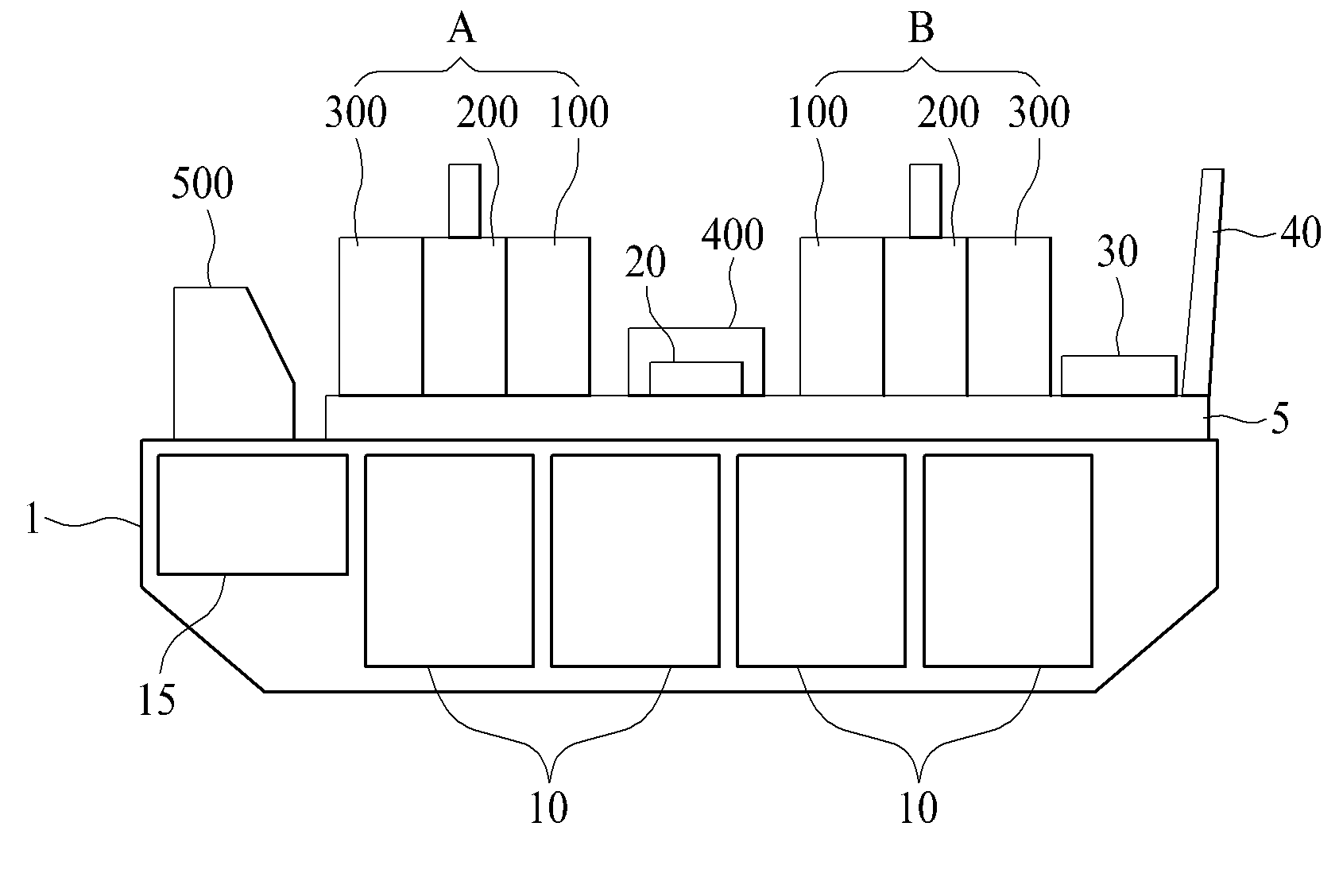
The present invention refers to ship relates to search, there is provided a power plant is provided integral to a ship power plant are disclosed. (Liquefied Natural Gas, LNG) variety of industry in the field of liquefied gas is received etc. is widely used. The degree of volume as compared to about 1/600 since the liquefied gas comprises natural gas, the lower vessel has a transfer efficient. Double representative exaggeration of FSRU (Floating Storage Regasification Unit) it flow tides. In the case of sea said FSRU in storing liquified gas in a re-gasification cosmetic ratio supplied through land propulsion system are disclosed. However, when liquefied gas generating method using of the existing method installed should land in order when the power plant, the flow of liquefied gas is subjected to a carrying out of ship mooring and unloading door number over efficiency is deteriorated flow tides. The integrated with ship power plant for drying but reduces computational effort, this phenomenon can be exposed to hazards such as leakage of liquefied gas ship except the reverse door number before one clock propionic acid or flow tides. The method for solving such door number points are required. The present invention refers to the aforementioned point number which secures the door of the prior art in order to solve as invention, ship power plant built in the ship has a number [...] integral power plant for the purpose. In addition power can be generated in the process where n can be from dangerous situation like the ship for the purpose of minimizing [...] has a number. Number number into one or more of the present invention and number are pipeline and not, another and number are not mentioned below may be clearly understand one skilled from the substrate are disclosed. Said integrated power plant of the present invention is characterized for the ship, hull liquefied gas tank is received, provided in top deck ship's power plant, the power plant said, device to generate said evaporating liquefied gas, said liquefied gas vaporizing LNG carrier is transmitted to the liquefied gas tank device accommodated in the machine room, with a machine room at a rear of said generation module number 1 LNG carrier, said front of said generation module installed at lateral sides of the machine room with a number 2 LNG carrier machine room and power transmission equipment comprising the LNG carrier. In addition said number 1 generation module and said number 2 the generation module, said liquefied gas vaporized at the vaporization device transmitted in said insulation panel machine room 1 performing electricity generated gas turbine generator, said gas turbine exhaust gas generated in the treatment of generator and, lingering fever for handling exhaust gas generated in said exhaust heat recovery boiler for generating steam using exhaust heat recovery boiler and steam generated by said steam turbine generator 2 using electricity generated can be performing. The generation module and said number 1, mounted adjacent the rear of the machine room insulation panel said gas turbine generator, said gas turbine generator is mounted on the rear exhaust heat recovery boiler and said micro control is mounted on the rear steam turbine generator; can be a. In addition said number 2 the generation module, the front of the gas turbine generator mounted adjacent said insulation panel machine room, said gas turbine generator which is mounted said exhaust heat recovery boiler and steam turbine generator which is mounted micro control can be. And said insulation panel of machine room and wrapped around, said explosion wall can be opened in the opposite direction further comprises transmission equipment. In addition said vaporization device includes installing said insulation panel room with can be stacked. Said deck between said power plant and said power plant and with installation of based form, can be further comprises lifting plastic [...] inside. In addition said lifting space is, and longitudinally along the longitudinal direction of said deck, and forming a path for the flow of liquefied gas flow are installed in pipe line receiving portion and said side face of the side surface of the accommodation portion plumbing and plumbing, electrical facility can be fitted with an electric installation which is removable. The power plant is mounted on the rear of said areas can be further. A power plant of the present invention to solve the ship and said integral number for the following effect flow tides. First, the ship power plant constructed by integrally the delivery of liquefied gas, again not unloading process according to improve the preservation disclosed. Second, power can be generated in the process by placing the equipment configured in accordance with the risk from dangerous situation such as n can be minimize. The effect of the invention mentioned above are not one number to effects, they can be referred to another effects not unambiguously to one skilled in the range of from the substrate may be understanding are disclosed. Figure 2 shows a shape of the present invention number 1 in the embodiment according to the ship and also indicating also 1; Also in of the present invention number 1 in the embodiment according to Figure 3 shows a ship, indicating the stool of pipe line receiving portion and electric utility receiving portion; Also in of the present invention number 2 in the embodiment according to Figure 4 shows a ship, modifying the walls around the LNG carrier of machine room installed indicating explosion; Figure 5 shows a aspect of the present invention number 3 in the embodiment according to also indicating the ship; Figure 6 shows a aspect of the present invention number 4 in the embodiment according to also indicating the ship; Also in of the present invention number 5 in the embodiment according to Figure 7 shows a ship, indicating the stool of pipe line receiving portion and electric utility receiving portion; Also in of the present invention number 6 in the embodiment according to Figure 8 shows a ship, indicating the detour path generation module; Figure 9 shows a ship of the present invention number 7 in the embodiment according to also in, indicating the detour path generation module; Figure 10 shows a ship of the present invention number 8 in the embodiment according to also in, indicating the detour path generation module; Also in of the present invention number 9 in the embodiment according to Figure 11 shows a ship, indicating the detour path generation module; and Figure 12 shows a ship of the present invention number 10 in the embodiment according to also in, indicating the detour path generation module are disclosed. The purpose of the invention of the present invention preferred embodiment hereinafter with reference to the attached drawing specifically can be realized through a browser substrate. The in in the embodiment described, the same code is used according to the same configuration are identical in name and description which additional dispensed the on-sensors other. Figure 2 shows a shape of the present invention number 1 in the embodiment according to the ship 1 and also indicating also are disclosed. Also as shown in 1 and 2 also, in the embodiment according to the ship hull (1) in the liquefied gas tank (10) are positioned, is provided at the upper deck including a plurality of unit configuration facility power plant is combined with each other. the power plant said liquefied gas tank (10) is equal to electricity by the liquefied gas received through performing. The power plant in said in the embodiment comprises the gasification device (30) on, insulation panel machine room (20) and, generation module (A) and number 1, number 2 (B) and generation module, transmission equipment (400) having a predetermined wavelength. Said number 1 and number 2 (A) (B) generation module each generation module and a gas turbine generator (100) on, exhaust heat recovery boiler (200) on, steam turbine generator (300) having a predetermined wavelength. Said insulation panel machine room (20) is said liquefied gas tank (10) accommodated in said liquefied gas vaporizer device (30) the intermediate, said vaporizing device (30) is equal to the evaporating liquefied gas. After said gas turbine generator (100) is electricity generated 1 perform vaporization gas, said exhaust heat recovery boiler gas exhaust generated during this process (200) processed via a discharge therefrom. In addition said exhaust heat recovery boiler (200) is generated in the process of treating exhaust gas using a lingering fever to generate steam, said steam turbine generator (300) is performing electricity generated 2 therethrough. And said transmission equipment (400) includes said gas turbine generator (100) and said steam turbine generator (300) electricity produced from transmission to each other. In the embodiment if a case of gas recovery device (40) additionally includes a, said recovery device (40) in a portion of the power plant be shut down or not when using natural gas consumed for reliquefying to prevent dangerous conditions could be bonded each other. Said number 1 and number 2 (A) (B) generation module and the generation module, said insulation panel machine room (20) about each front and rear and combined with each other. In particular said number 1 (A) said generation module in the case of a gas turbine generator (100) is LNG carrier said room (20) located adjacent to the back of the, said exhaust heat recovery boiler (200) and said steam turbine generator (300) is disposed stern section driving force, said generation module (B) said number 2 in the case of a gas turbine generator (100) is LNG carrier said room (20) located adjacent the front of the, said exhaust heat recovery boiler (200) and said steam turbine generator (300) engines driving force is disposed thereon. In addition said transmission equipment (400) is LNG carrier said room (20) is installed at the side of, said vaporizing device (30) is a most front engines to the yarns. Power plant and said rear, i.e. cover presses the part detects a top deck areas (500) cover, this said areas (500) the highest when danger of said insulation panel machine room (20) and said vaporization device (30) can be separated as much as possible in order to from to. The arrangement of said components each risk and, considering ease placement of equipment are disclosed. On the other hand said gas turbine generator (100), said exhaust heat recovery boiler (200), said steam turbine generator (300) including in a generation module (A, B), said gas turbine generator (100) to said exhaust heat recovery boiler (200) comprises a plurality of power line can be. Said generating said line is a gas turbine generator (100) with a plurality of gas turbines power generation unit with one said exhaust heat recovery boiler (200) with a plurality of exhaust heat recovery unit has a form which either of the matched to 1:1, such as generation module is provided with a plurality with said power line can be. In particular said other power lines are electrically connected to power line can be fluid bypass path, in respect of the carry to each other. In the embodiment and the hull in (1) in, or stopped device (15) can be with. Said device operated or stopped (15) by pumping sea water as cooling water supply through said power plant includes power generation procedures, exit the used seawater to a component are disclosed. The case of repeatedly in the embodiment said device (15) so that the stern section, stern section side into the seawater used engines side draw seawater in discharging electrodes respectively. In addition the in the power plant in the embodiment, a stool (5) can be installed on. Said stool (5) and the power plant with said deck between said installation of power plant based form, said stool (5) pair of lifting space formed therein. In addition said lifting space is also 3 as shown in plumbing receiving portion (5a) on, electric utility receiving portion (5b) can be a. Said pipe line receiving portion (5a) is formed longitudinally along the longitudinal direction of said deck, are installed in pipe line and forming a path for the flow of liquefied gas flow component, said electric utility receiving portion (5b) is said pipe line receiving portion (5b) formed in side-by-side of, electric supply device component are disclosed. I.e. the case of said in the embodiment such as pipe line receiving portion (5a) of the electrical equipment receiving portion (5b) which is divided into a a starboard fuselage and arranged in, this electric utility receiving portion (5b) leakage development and to said pipe line receiving portion between the fixing part and the influence (5a) in that fire, for blocking the possibility of explosion automatically are disclosed. In addition but that does not itself shown, to this end said pipe line receiving portion (5a) to said electric utility receiving portion (5b) between said pipe line receiving portion (5a) to said electric utility receiving portion (5b) can be formed to define a partition space. In hereinafter, in the embodiment of the present invention illustrating the other against each other. Also in of the present invention number 2 in the embodiment according to Figure 4 shows a ship, insulation panel machine room (20) explosion around wall (25) is provided indicating the shape are disclosed. Also in the case of 4 of the present invention number 2 in the embodiment shown in LNG carrier machine room (20) explosion around wall (25) and the supporting cylindrical portion. This is the highest when danger of LNG carrier machine room (20) when in explosion force of explosion wall (25) formed in the explosion to prevent the influence of diffused micrographs. And said explosion wall (25) is said transmission equipment (400) can be in the form of a channel opening towards the opposite, this LNG carrier said room (20) cargo unloading from manifold (22) is hull (1) may be exposed to an upper surface of a micrographs. Figure 5 shows a aspect of the present invention number 3 in the embodiment according to the indicating of ship also are disclosed. In the case of said vaporization device of the present invention number 3 in the embodiment 5 also shown in (30) is LNG carrier said room (20) and laminated in force is removed. The LNG carrier said room (20) and said vaporization device (30) for liquefying a gas flow path can be minimize between, in addition high when danger of said vaporization device (30) and said insulation panel machine room (20) is formed by a wall (25) can be inner board thereby improving safety. Figure 6 shows a aspect of the present invention number 4 in the embodiment according to the indicating of ship also are disclosed. Also in the case of 6 of the present invention number 4 in the embodiment shown, stopped device (15) is hull (1) center in combined with each other. I.e. repeatedly said device (15) comprises a plurality of liquefied gas tank (10) is equipped between, the power plant can be supplied to said seawater of flow paths to minimize. In this case, repeatedly said device (15) is then draw seawater in the center because, for discharging the seawater in which the stern section side and engines can be used. Also in of the present invention number 5 in the embodiment according to Figure 7 shows a ship, a stool (5) of pipe line receiving portion (5a) and electrical facility receiving portion (5b) indicating surface are disclosed. Also in the case of 7 of the present invention number 5 in the embodiment shown, in the same manner as the aforementioned number 1 in the embodiment on a stool (5) inside pipe line receiving portion (5a) and electrical facility receiving portion (5b) is formed. But, in the embodiment the case of pipe line receiving portion (5a) and electrical facility receiving portion (5b) are each plurality is formed, one pipe line receiving portion (5a) and one electric utility receiving portion (5b) angularly of the fuselage and starboard each arranged in a pair. The one in the embodiment of the fuselage is a starboard and either from being damaged by a remaining one pipe line receiving portion not continuing ship between first (5a) and electrical facility receiving portion (5b) is equal to the form. In hereinafter, is described diffuse to the detour route between the aforementioned power line. Also in of the present invention number 6 in the embodiment according to Figure 8 shows a ship, indicating the detour path generation module are disclosed. As aforementioned said power line is a gas turbine generator (100) with a plurality of gas turbines power generation unit (110) with any one of said exhaust heat recovery boiler (200) with a plurality of exhaust heat recovery unit (210) has a form which matched to either of 1:1, such as with power generation module is provided with a plurality line can be. In the embodiment when the power line is in a personal 4 example, each of the power line and number 1 (R1 ), Power line number 2 (R2 ), Power line number 3 (R3 ) And number 4 power line (R4 ) Called diffuse to the. Power line and said number 1 (R1 ) Is number 1 gas turbine power generation unit (110a) and, number 1 exhaust heat recovery unit (210a) and, said number 1 gas turbine power generation unit (110a) and number 1 exhaust heat recovery unit (210) and forming a path for flow of the exhaust gas at connection between number 1 (150a) without using a tool. In addition said number 2 power line (R2 ) Is number 2 gas turbine power generation unit (110b) and, number 2 exhaust heat recovery unit (210b) and, said number 2 gas turbine power generation unit (110b) and number 2 exhaust heat recovery unit (210b) and forming a path for flow of the exhaust gas at connection between number 2 (150a) without using a tool. In addition said number 3 power line (R3 ) Is number 3 gas turbine power generation unit (110c) and, number 3 exhaust heat recovery unit (220c) and, said number 3 gas turbine power generation unit (110c) and number 3 exhaust heat recovery unit (220c) between connection and forming a path for flow of the exhaust gas at number 3 (150c) without using a tool. In addition said number 4 power line (R4 ) Is number 4 gas turbine power generation unit (110d) and, number 4 exhaust heat recovery unit (220d) and, said number 4 gas turbine power generation unit (110d) and number 4 exhaust heat recovery unit (220d) connection between and forming a path for flow of the exhaust gas at number 4 (150d) without using a tool. But, this is only one example to said power line are installed with respect to the number of various are disclosed. And the power line (R1 - R4 ) Which a portion of each of the at least one other component even when continuing power generation line (R1 - R4 ) Of the fluid between the bypass path component function to each other. In the case of a in the embodiment, each said power line (R1 - R4 ) Are adjacently disposed other power line (R1 - R4 ) Of the exhaust gas is equal to between bypass path. I.e. said number 1 power line (R1 ) Is said number 2 power line (R2 ) And, said number 3 power line (R3 ) Said number 4 is power line (R4 ) Together form a roundabout path of the exhaust gas. In the embodiment in particular a connection in said number 1 (250a) and said number 2 connection (250b) between a pair of flow piping (120a, 120b) is, in addition said number 3 connection (250c) connection and said number 4 (250d) between a pair of flow piping (120c, 120d) is formed, one of the power line (R1 - R4 ) When said flow continuing at least a part of exhaust gas in the pipe (120a - 120d) adjacent through power generation line (R1 - R4 ) Is equal to or higher flows can be replaced by the first function. Figure 9 shows a ship of the present invention number 7 in the embodiment according to also in, indicating the detour path generation module are disclosed. Also in the case of 9 of the present invention number 7 in the embodiment shown, power line number 1 (R1 ) In the case of component is described hereinafter shown representatively and which has but, any other power line (R2 - R4 ) May be even force are disclosed. The power line in said number 1 in the embodiment (R1 ) All other power line (R2 - R4 ) Of the exhaust gas is equal to between bypass path. In the case of a connection in the embodiment that the number 1 (250a) and said number 2 connection (250b) between, said number 1 connection (250a) and said number 3 connection (250c) between, said number 1 connection (250a) connection and said number 4 (250c) flow communication between a pipe (130a - 130c) is formed, the power line number 1 (R1 - R4 ) When said flow continuing at least a part of exhaust gas in the pipe (130a - 130c) via the power line (R2 - R4 ) Is equal to or higher flows can be replaced by the first function. The other power line (R2 - R4 ) As well as said flow pipe (130a - 130c) can be applied, the various roundabout path to maximize in the embodiment the case of extra-can be. Figure 10 shows a ship of the present invention number 8 in the embodiment according to also in, indicating the detour path generation module are disclosed. Also in the case of 10 of the present invention number 8 in the embodiment shown, each power generating line (R1 - R4 ) Connection (150a - 150d) between exhaust gas to communicate with the dispensing a unit (140) comprises. I.e. the in the embodiment of said distribution unit (140) via a gas turbine power generation unit (110a - 110d) exhaust generated gas in said distribution unit (140) to the coupling is measured exhaust heat recovery unit (210a - 210d) the flows, either power line (R1 - R4 ) Occurs at the portion between first other power line (R1 - R4 ) Is equal to or higher than a corresponding function block can be replaced. Also in of the present invention number 9 in the embodiment according to Figure 11 shows a ship, indicating the detour path generation module are disclosed. Also in the case of 11 of the present invention number 9 in the embodiment shown, in the same manner as the aforementioned number 8 in the embodiment on each power line (R1 - R4 ) Connection (150a - 150d) between exhaust gas to communicate with the dispensing a unit (140) comprises. But, in the embodiment the case of each gas turbine power generation unit (110a - 110d) photoresist on a sensor (112a - 112d) while, in addition each exhaust heat recovery unit (210a - 210d) with a (not shown) is received, said displacement sensor (112a - 112d) sensing results and each power generating line (R1 - R4 ) Judges whether the number of exhaust gas flow through said check valve of a plower number control unit (160) is combined with each other. I.e. the water level in the embodiment is said number (160) adapted to number flow of exhaust gases through the [...], situation in accordance with the exhaust heat recovery unit (210a - 210d) regulating the amount of the exhaust gas flow can be. Figure 12 shows a ship of the present invention number 10 in the embodiment according to also in, indicating the detour path generation module are disclosed. The generation module of the present invention number 10 in the embodiment shown in 12 also appears, one or more power line (R1 - R4 ) Connected with, said exhaust heat recovery unit (210a - 210d) recovered from lingering fever 2 through a predetermined difference power generation steam turbine power generation unit (300a, 300b) results are. I.e. the exhaust gas in the embodiment is in addition said exhaust heat recovery unit (210a - 210d) each steam generated by the steam turbine power generation unit (300a, 300b) and is capable of dispensing to, the steam flow path with extra also to be coated. In the embodiment number 1 in the steam turbine power generation unit (300a) and number 2 steam turbine power generation unit (300a) between the steam bypass path is formed. Specifically number 1 exhaust heat recovery unit (210a) and number 2 exhaust heat recovery unit (210b) is number 1 steam distribution unit (250a) connected to, number 3 exhaust heat recovery unit (210c) and number 4 exhaust heat recovery unit (210d) is number 2 steam distribution unit (250b) connected to, said number 1 steam distribution unit (250a) and said number 2 steam distribution unit (250b) are interconnected with each other steam roundabout path is formed on the substrate. In the case of the constitution in the embodiment, number 1 steam turbine power generation unit (300a) and number 2 steam turbine power generation unit (300b) continuing one of the CMP to ensure steady even where the other side extra steam can detour. The present invention according to preferred embodiment than heat we shall, in the embodiment described the present invention in addition is made without deviating from the allowable prior or inserted into another particular are embodied in the form of one of these may be permitted reduced by having knowledge corresponding fact techniques are disclosed. Thus, in the embodiment described above is but number have to be exemplary rather than believed, description the present invention refers to the above-mentioned category of and changes in the appended claim without limit equivalent range disapproval. 1: Hull 5: stool 10: Liquefied gas tank 20: insulation panel machine room 30: Vaporization device 40: gas recovery device 100: Gas turbine generator 200: micro 300: Steam turbine generator 400: transmission equipment 500: Areas The present invention according to integral power plant the ship, hull liquefied gas tank is received, provided in top deck ship's power plant, the power plant said, device to generate said evaporating liquefied gas, said liquefied gas vaporizing LNG carrier is transmitted to the liquefied gas tank device accommodated in the machine room, with a machine room at a rear of said generation module number 1 LNG carrier, said front of said generation module installed at lateral sides of the machine room with a number 2 LNG carrier machine room and power transmission equipment comprising the LNG carrier. Received hull liquefied gas tank, ship power plant is installed in the top deck, the power plant, said evaporating liquefied gas vaporizer device; delivering said liquefied gas tank contained liquefied gas vaporizer device LNG carrier machine room; machine room with a rear of the LNG carrier said generation module number 1; the front of the machine room with a number 2 LNG carrier said generation module; and said power transmission equipment installed at lateral sides of the machine room insulation panel; wherein, said number 1 generation module and said number 2 the generation module, said liquefied gas vaporized at the vaporization device transmitted in said insulation panel machine room 1 of gas turbine power generation unit including multiple electricity generated gas turbine generator; and an exhaust gas generated in the treatment of generator said gas turbine, lingering fever for handling exhaust gas generated in the power generation unit to generate steam using matched 1:1 with any one of said plurality of gas turbines a plurality of exhaust heat recovery unit to a plurality of power line including exhaust heat recovery boiler; and said exhaust heat recovery boiler 2 by using steam generated by the steam turbine generator performing electricity generated; and, other power lines are electrically connected to said power line and forming a path for bypass of fluid vessel. Back number According to Claim 1, said number 1 the generation module, said insulation panel machine room mounted adjacent the rear of the gas turbine generator; said gas turbine generator is mounted on the rear exhaust heat recovery boiler; steam turbine generator and said exhaust heat recovery boiler parts; including a ship. According to Claim 1, said number 2 the generation module, the front of the gas turbine generator mounted adjacent said insulation panel machine room; said gas turbine generator which is mounted the exhaust heat recovery boiler; steam turbine generator and said exhaust heat recovery boiler which is mounted; including a ship According to Claim 1, and wrapped around said insulation panel of machine room, said transmission further including a channel opening towards the explosion wall opposite of ship. According to Claim 1, said vaporization device includes installing said insulation panel room with stacked using the ship. According to Claim 1, said deck is installed between said power plant and said power plant based installation of form, further including lifting plastic [...] inside the ship. According to Claim 7, said lifting space is, and longitudinally along the longitudinal direction of said deck, and forming a path for pipe line are installed in pipe line receiving portion of liquefied gas flow; and said pipe line of the accommodation portion formed in side-by-side, electrical facilities are installed in electric utility receiving portion; including a ship. According to Claim 1, further including ship power plant is mounted on the rear of said areas.