박막 증착 장치 및 방법
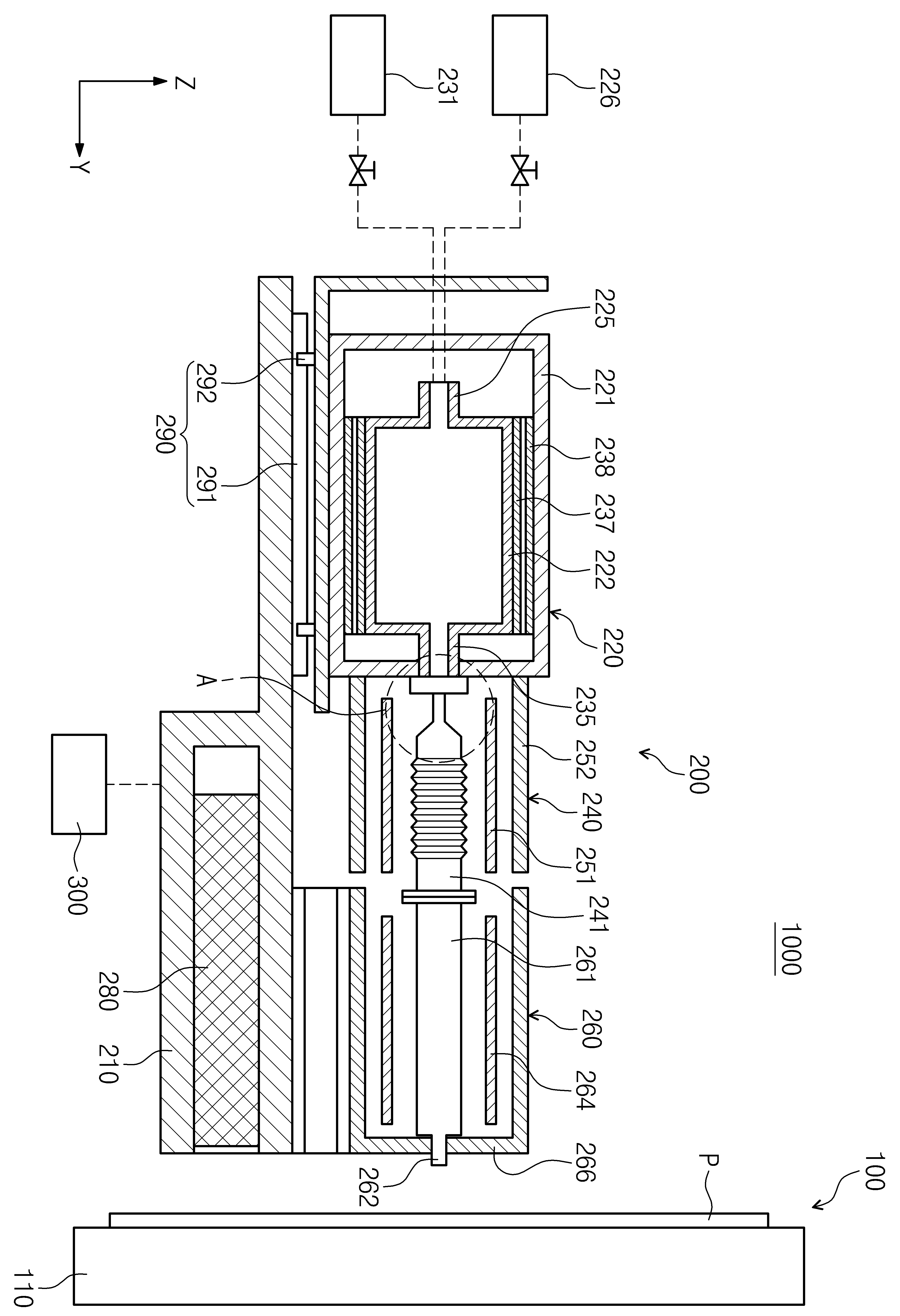
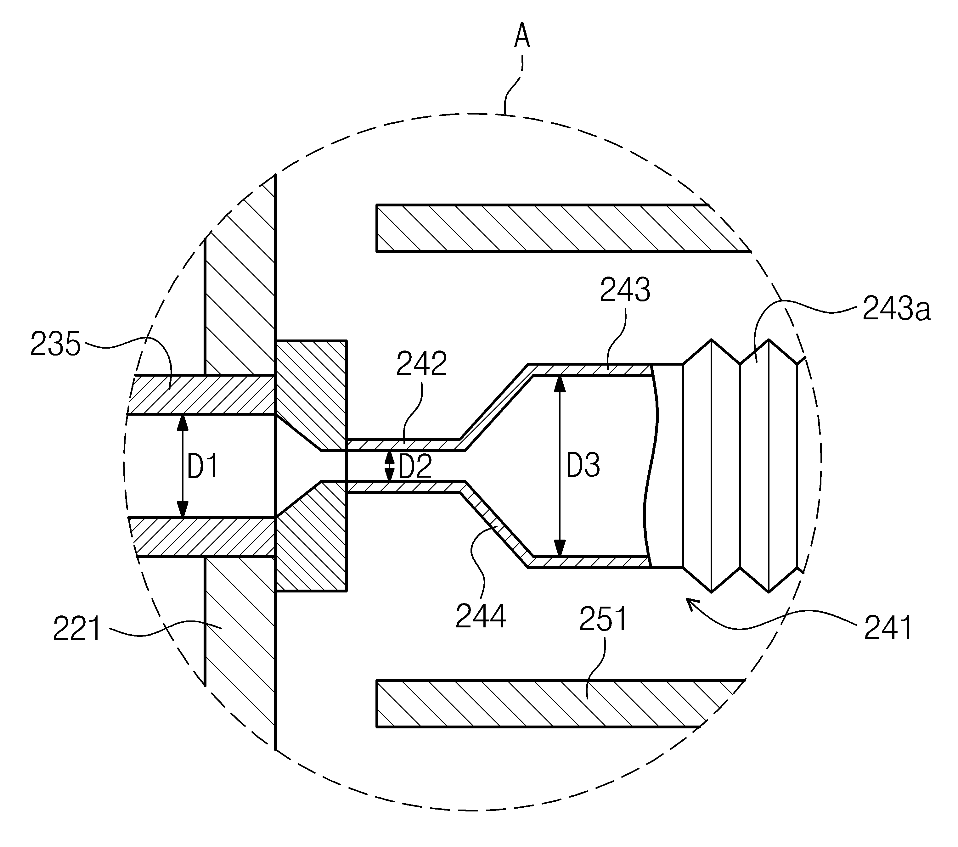
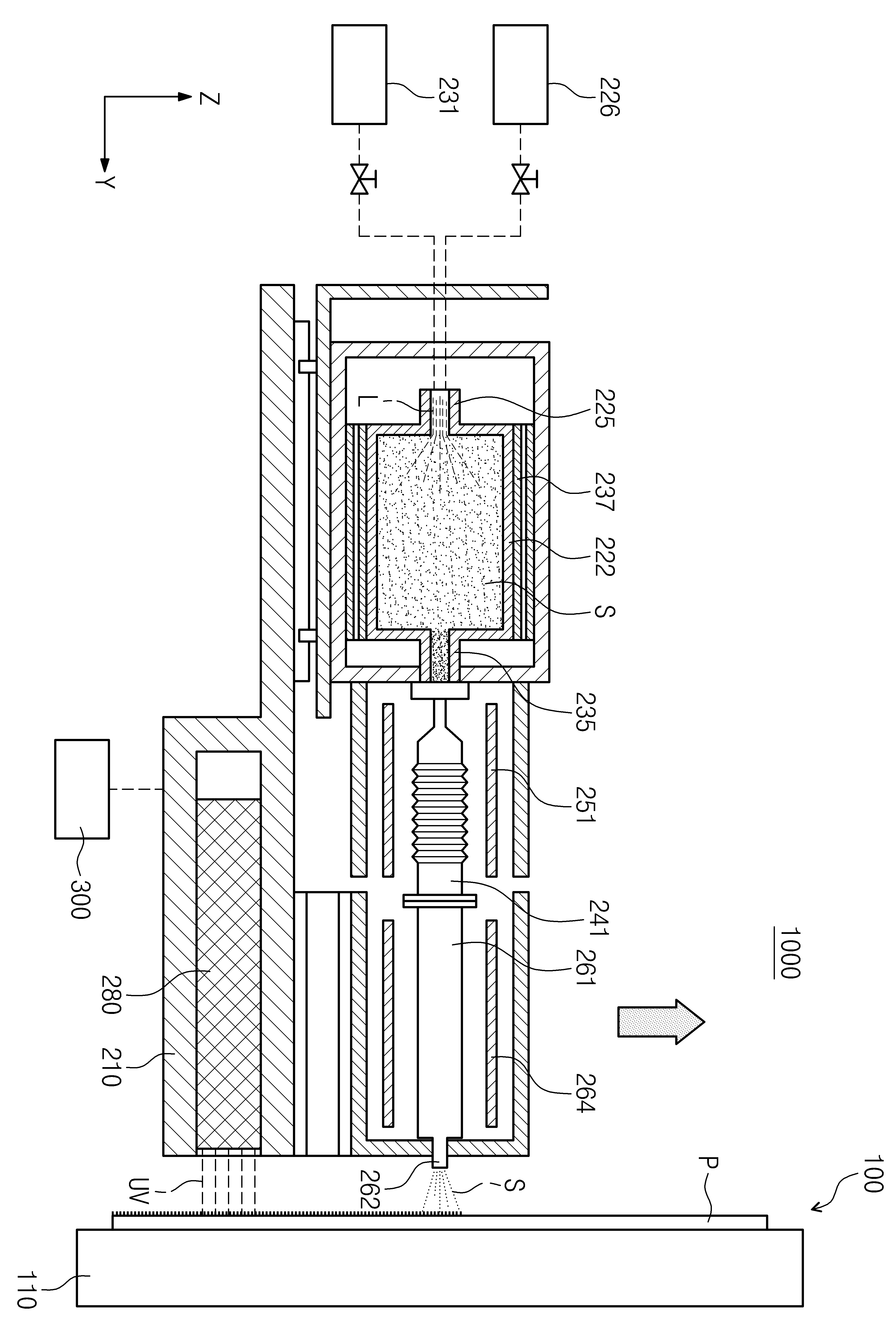
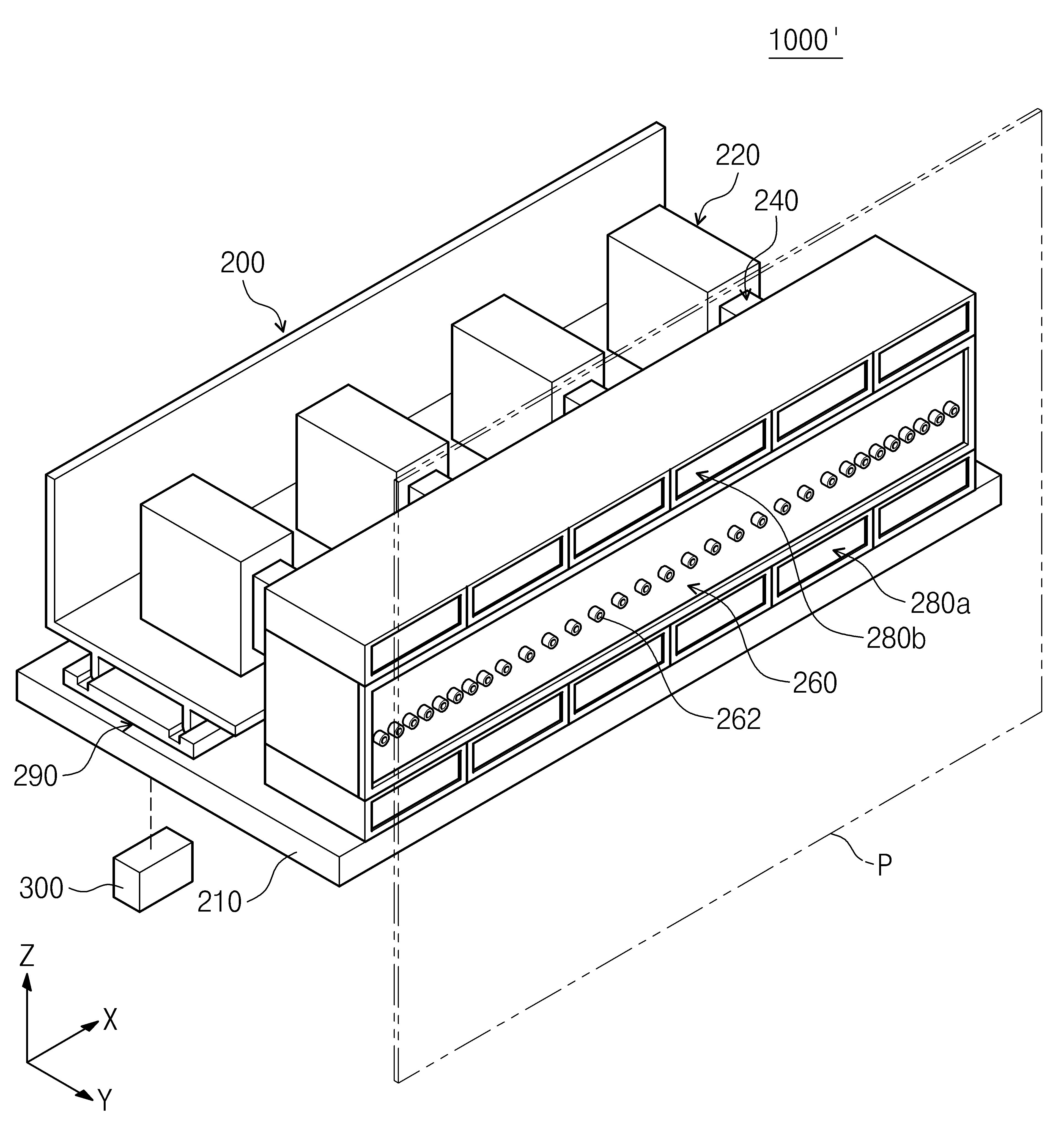
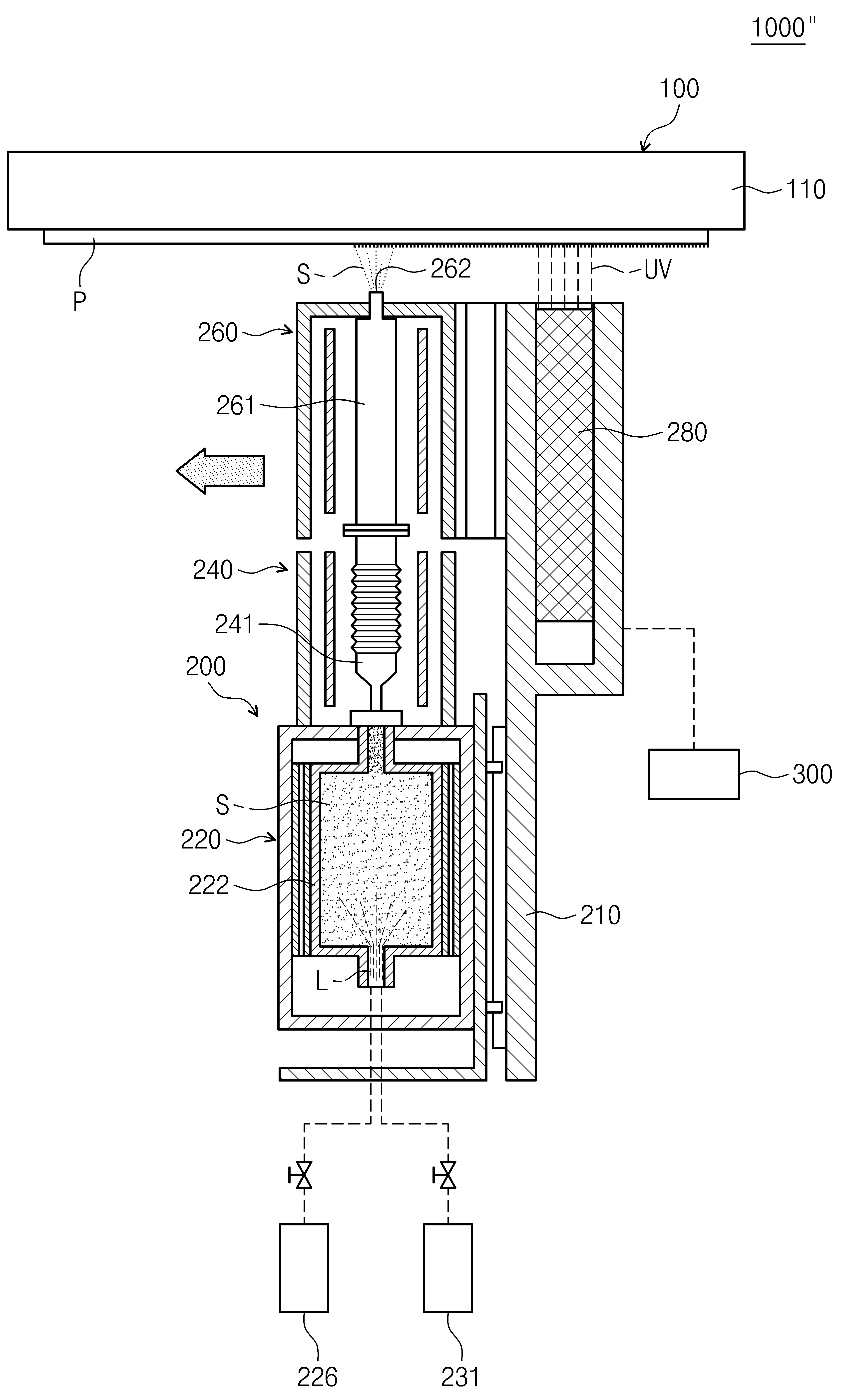
The present invention refers to substrate processing device relates to, more particularly depositing a thin film on the device are disclosed. One display device, organic light emitting elements is an organic light emitting display device excellent in contrast a wide visual field angle as well as from a group as a next generation display device is advantageous in that a response speed etc. have. Generally, organic light emitting display device and a cathode electrode is an anode electrode and the electrons injected into the light emitting visible light can be recombined in implementing organic light-emitting layer. The organic light emitting display device characteristics in which the organic emissive layer is an anode electrode and a cathode electrode direction [syang together, electron injection layer, an electron transport layer, a hole transport layer and hole injection layer of organic layer by selectively etc. further insertion. On the other hand, organic light emitting display device of electrodes, the organic light emitting layer and the organic layer can be formed various method, one of these deposited method are disclosed. Deposition process may transfer of to supply substrate, such as returning the substrate during the deposition material is deposited to be inspected by placing the cured material. Thin film deposition device and the evaporation material is a deposition chamber and deposition material structure to separate the curing portion curing device the whole length of the door number increased number ball flow tides. In particular foot print (foot print) and process time (tact time) when processing a large substrate device is increased. A device and method of the present invention in the embodiment are large space changing number substrate. In addition, device of the present invention in the embodiment are foot print and removed a number space device and method substrate. In addition, the present invention refers to deposition material is fed into the film deposition device and method capable of preventing nozzle clogging in the process where a number substrate. Thin film deposition device according to an embodiment of the present invention substrate support that supports a substrate; evaporation deposition material into a vapor, said vapor of said substrate deposition material supplying deposition won; and said deposition source relative to the substrate support said deposition won by relatively moving the mobile having a predetermined wavelength. In addition, the deposited material to receive the fixing ribs formed therein said vapor deposition material evaporates into said evaporation chamber; said vapor of said deposition material substrate an infrared laser is implemented nozzle section; said nozzle sections connecting said evaporation chamber, a steam supply for supplying coolant to said transfer of said nozzle; and said nozzle section and on one side of, said region comprising the deposited material deposited remover can be said to be inspected. In addition, said substrate supporting said substrate support is vertically erected, the lower end of said substrate between said deposition won the mobile portion vertically to move the deposition source in said top section, said at least one of said upper and lower the irradiation of the nozzle unit can be located. In addition, said heat sink contacts said surface for supporting said deposition material is deposited this time, said nozzle section has said substrate support at the bottom of said deposition material supplies a vapor of said substrate, said optical axis said deposition source in the movement direction of said at least one of the front and rear of the nozzle unit can be located. In addition, ultraviolet light irradiation can be said. In addition, the invention relates to a plastic container said evaporating chamber; connected to said container, said container an interior void of a spray nozzle spraying a mist deposited material liquid shape; and said outer and, said heater heating number 1 can be the inner space of the container. In addition, said evaporation chamber and said steam supply portions connecting said container, said container is smaller than the inner diameter further comprises the transfer nozzle number 1, number 2 is connected with the steam supply portion with an internal diameter smaller than said number 1 said transfer nozzle number 1 region, said number 2 and number 3 has the container is smaller than the diameter that is larger than said inner diameter portion connected with a nozzle number 2 region, and the centrally located region diameter is gradually increased from said number 2 from said number 1 region connects said number 2 region said number 1 number 3 region can be the feed nozzle. In addition, the envelop said steam feed said supply nozzle, said super-cooled in the delivery nozzle number 2 heater; and said number 2 and has a heater, an outer perimeter of said number 2 heater further comprises a cooling block can be. In addition, relatively moves said evaporating chamber to said exhaust gas deposition parts by said moveable portion further includes evaporating chamber, said steam supply portion connecting said container and said nozzle sections, said evaporating chamber having a region with a shape to follow the movement of wrinkles can be supply nozzle. In addition, said spray nozzle of said deposition material for said evaporation chamber liquid deposition material supply; and said spray nozzle further comprises a gas supply carrier gas can be. Thin film deposition method according to an embodiment of the present invention is evaporated into a vapor deposition materials, an outlet opening is formed on said substrate through the nozzle to the plane of the film formation apparatus is mixed, provides the positioned, said nozzle section has said transfer of said moves relative to the substrate and can be mixed. In addition, end to said nozzle portion of said linear movement can be. In addition, vertically standing on said substrate is supported, said lower end of said nozzle portion moves between the top substrate can be. In addition, the reactive species comprises depositing said this time said substrate is arranged, said nozzle portion at the bottom of said substrate can be moved. In addition, the direction of travel of said at least one part of said nozzle portion of the nozzle unit is a light-irradiation number is ball shear, moves with the nozzle section and said optical axis said deposited material deposited said substrate region can be irradiated with light. In addition, ultraviolet light irradiation can be said. In addition, deposition material said container with an internal diameter smaller than said container and to spray mist spray nozzle this liquid phase of said deposition material shape, heating the inside of the container can be said to be concave. In addition, said carrier gas with said liquid deposition material can be atomized with the inside of the container. In addition, said carrier gas is an inert gas at a can. The are of the present invention in the embodiment, a substrate support fixedly positioned relative to the deposition source moves, for making it possible to perform a large-sized substrate for deposition process can be hereinafter. In addition, the are of the present invention in the embodiment, at least one chamber is used for supplying a sequence of deposition material and curing of the deposition material, foot print and can be connected with a device. In addition, the are of the present invention in the embodiment, since the lower end of the carrier gas supplied with quantities of liquid deposited material and high voltage state can be. Figure 1 shows a device of the present invention representing one in the embodiment according to thin film deposition sensors mounted thereon also are disclosed. Figure 2 shows a thin film deposition device is representing cross-sectional drawing of Figure 1. Figure 3 shows a region 'A' indicating the by increasing a of Figure 2 also are disclosed. Figure 4 shows a device of the present invention representing one in the embodiment according to depositing a thin film on the thin film deposition process is also are disclosed. Figure 5 shows a device of the present invention representing other thin film deposition in the embodiment according to also are disclosed. In the embodiment of the present invention representing another Figure 6 shows a different thin film deposition device sensors mounted thereon also are disclosed. Figure 7 shows a cross-sectional drawing of Figure 6 representing thin film deposition device are disclosed. According to a preferred embodiment of the present invention example hereinafter with reference to the attached drawing that are directionally depositing thin film device and method described as follows. The present invention is connected to the described, publicly known or a function of the associated specific description the subject matter of invention description if a haze can be decided to be dispensed to each other. Figure 1 shows a perspective view of the present invention representing and also one in the embodiment according to thin film deposition device, Figure 2 shows a cross-section of Figure 1 representing thin film deposition device are disclosed. The reference also 1 and 2 also, thin film deposition device (1000) includes a substrate (P) (P) transfer of part to form a thin film on one surface of the substrate. Thin film deposition device (1000) substrate support (100), deposition won (200), and deposition won the mobile portion (300) having a predetermined wavelength. Substrate support (100) support the foot panel 50. substrate (P). The substrate (P) substrate for flat panel display device, a plurality of flat panel display device can be set to form a mother glass (mother glass). Deposition won (200) is evaporated into a vapor deposition materials, transfer of the substrate (P) supplied. Organic light emitting devices for organic thin film material which has a deposition material. Charge transport material deposition material, charge generating material, light-emitting material is mixed 1308. ball number. Deposition won the mobile portion (300) substrate support (100) for deposition won (300) such as returning relatively moves. Setting up each hereinafter detailed as follows. Substrate support (100) which is located in the fixed, support the foot panel 50. substrate (P). Substrate support (100) includes a rectangular supporting plate (110) which, support plate (110) substrate has a wider area. Substrate (P) includes a support plate (110) fixed on one surface of which is supported. Support plate (110) includes a supporting substrate using electrostatic force (P) can be. Alternatively, support plate (110) substrate by vacuum adsorption (P) using enhanced support, mechanism supporting a substrate (P) can be. Support plate (110) supporting part of the substrate (P) vertically disposed thereon. (P) in the vertical direction is formed on the substrate support plate (110) are supported. Deposition won (200) substrate support (100) on one side of substrate. Deposition won (200) (P) substrate support plate (110) positioned adjacent one side of the substrate. Deposition won (200) includes a base (210), and the evaporating chamber (220), steam supply (240), the nozzle section (260), irradiation (280), and the evaporating chamber and moveable portion (290) having a predetermined wavelength. Base (210) is deposition won (200) various device supporting substrate. An evaporation chamber (220), steam supply (240), the nozzle section (260), irradiation (280), and the evaporating chamber and moveable portion (290) includes a base (210) respectively provided on the substrate. An evaporation chamber (220) is evaporated into a vapor deposition materials, steam supply (240) is transfer of nozzle unit (260) is supplied to the. The nozzle section (260) includes a substrate (P) and transfer of release, irradiation (280) the deposited material is selected from a (P) region to be inspected substrate. The moveable portion and the evaporating chamber (290) includes a steam supply (240) to an evaporation chamber (220) such as returning relatively moves. An evaporation chamber (220) is a plurality of can be arranged in a row. Each evaporating chamber (220) to create a vapor and vapor deposition material transfer of supply (240) is supplied to the. Hereinafter, an evaporation chamber (220) are referred to as number 1 direction (X) direction and arranged, when looking at the top, number 1 number 2 (Y) direction perpendicular to the direction (X) direction is combined with a load. And, number 1 and number 2 (X) (Y) (Z) direction perpendicular direction direction direction number 3 is combined with a load. The number 2 (Y) direction and the evaporating chamber (220), steam supply (240), and nozzle section (260) is arranged parallel with direction and, number 3 direction (Z) direction is connected in parallel disclosed. Each evaporating chamber (220) is identical 1308. ball number. An evaporation chamber (220) chamber (221), container (222), spray nozzle (225), deposition material supply (226), carrier gas supply portion (231), transfer nozzle (235), number 1 heater (237), and cooling block (238) comprises. Chamber (221) inner space formed therein. Chamber (221) is a variety of device number ball 1308. Container (222) the chamber (221) is located inside the other. Container (222) of processing space formed therein. Container (222) the deposited material evaporates into vapor sealed space in the internal space of the ball number encoded. Container (222) rear end spray nozzle (225) formed on an active region, shear transfer nozzle (235) is coupled. Spray nozzle (225) container (222) has a smaller than the inside diameter of the target. Spray nozzle (225) a mist deposited material liquid container shape (222) atomized into the inner space of the substrate. Spray nozzle (225) is e writing M0 (atomizer). Deposition material supply (226) on the carrier gas supply unit (231) are each spray nozzle (225) and connected thereto. Deposition material supply (226) includes a liquid deposition material spray nozzle (225) are formed by supplying, carrier gas supply portion (231) is carrier gas spray nozzle (225) is supplied to the. The carrier gas comprises an inert gas. Liquid deposited material and carrier gas together spray nozzle (225) to feed. Liquid deposited material and carrier gas may spray nozzle (225) in passing through compressed and, container (222) are fed into a bored in the process of injection into the mist. The carrier gas passing the, deposition material by spray nozzle (225) of clogging can be prevented. Number 1 heater (237) comprises a vessel (222) encoded number to wrap around the ball. Number 1 heater (237) communicates heat generates, container (222) heated interior. Injection into mist deposition material number 1 heater (237) heated by heat transferred from the vapor form container (222) internal remain on the substrate. Container (222) remain on the internal steam amount increases more than deposition material container (222) increased internal pressure. Container (222) increase transfer of pressure transfer nozzle (235) introduced into the substrate. Figure 3 shows a region 'A' indicating the by increasing a of Figure 2 also are disclosed. With reference also to the 3 1 also, transfer nozzle (235) container (222) is smaller than the inner diameter (D1) is has a number 1. Transfer of a transfer nozzle (235) in passing through the compressed substrate. Cooling block (238) number 1 the heater (237) to encoded wrapped around ball number. Cooling block (238) number 1 the heater (237) cooling in the region of the reaction chamber. Cooling block (238) number 1 the heater (237) so as generated in servicing the peripheral device are heated. Steam supply (240) is an evaporation chamber (220) each connected thereto. Steam supply (240) is number 2 (Y) direction to an evaporation chamber (220) arranged in front of the other. Steam supply (240) supply nozzle (241), number 2 heater (251), and cooling block (252) comprises. Supply nozzle (241) is controlled nozzle (235) and connected thereto. Supply nozzle (241) is number 1 region (242), number 2 region (243), and number 3 region (244) has a. Number 1 region (242) is controlled nozzle (235) connected with the, transfer nozzle (235) inner diameter (D1) smaller than the inner diameter (D2) of number 1 to number 2. Number 2 region (243) is number 1 region (242) has a diameter (D3) greater than the inner diameter (D2) of number 2 number 3. Number 3 region (244) is number 1 region (242) and number 2 region (243) positioned between the, number 1 region (242) and number 2 region (243) connecting substrate. Number 3 region (244) is number 1 region (242) from number 2 region (243) to ball diameter is gradually increased from a number encoded. Number 3 region (244) funnel (funnel) of the prism configuration. The transfer of number 1 region (242) is compressed and allowed to pass through the material, number 3 region (244) and number 2 region (243) through volume expansion with each other. The, deposition a vapor which can be kept. Number 2 region (243) the major region (243a) comprises. Corrugated region (243a) is an evaporation chamber (220) and the movement of the shape with each other. An evaporation chamber (220) is number 1 (X) direction to move the steam supply (240) encoded the same linear alignment. During this process the crushable region (243a) is an evaporation chamber (220) and the movement of the shape with each other. Number 2 heater (251) supply nozzle (241) is around ball number, supply nozzle (241) 35a.. Number 2 heater (251) communicates heat generates, supply nozzle (241) heated interior. Supply nozzle (241) remain on the inside deposition material steam strips the number 2 heater (251) to provide the heater heats heat transferred from state being maintained. Cooling block (252) is number 2 heater (251) is around ball number, number 2 heater (251) surrounding substrate. Cooling block (252) is number 2 heater (251) cooling in the region of the reaction chamber. Cooling block (252) is number 2 heater (251) so as generated in servicing the peripheral device are heated. The nozzle section (260) has a steam supply (240) which is located in front of the, steam supply (240) on connected thereto. The nozzle section (260) is discharge nozzle (261), number 3 heater (264), and cooling block (266) comprises. The discharge nozzle (261) is a plurality number ball, number 1 (X) along the direction parallel to the substrate. The discharge nozzle (261) are number 1 (X) direction (P) substrate width within a range corresponding to the lungs. Each discharge nozzle (261) is supply nozzle (241) and connected thereto. The discharge nozzle (261) on the front end outlet (262) is formed. Outlet (262) is a transfer of emit. (P) of the width of the substrate in the region corresponding to transfer of number 1 is supplied. Number 3 heater (264) is discharge nozzle (261) is around ball number, discharge nozzle (261) 35a.. Number 3 heater (264) generates a communicates heat, the heat discharge nozzle (261) heated interior. The discharge nozzle (261) remain on the inside deposition material steam strips the number 3 heater (264) to provide the heater heats heat transferred from state being maintained. Cooling block (266) is number 3 heater (264) is around ball number, number 3 heater (264) surrounding substrate. Cooling block (266) is number 3 heater (264) cooling in the region of the reaction chamber. Cooling block (266) is number 3 heater (264) so as generated in servicing the peripheral device are heated. The remover (280) the deposited material is applicable to substrate (P) region to be inspected substrate. The remover (280) has a plurality number is ball, number 1 (X) direction each other diametrically disposed thereon. The remover (280) are released into nozzle number 1 (X) direction (261) corresponding to such a width as or a width disposed thereon. The remover (280) is mounted part (260) can be at least one of located at the top and bottom. The remover (280) is mounted part (260) and the predetermined interval away the nozzle section (260) to be located beneath can be. The remover (280) is ultraviolet light can be irradiated. The remover (280) is ultraviolet light emitting diode (UV LED) without using a tool. (P) substrate deposited deposition material remover (280) are cured by light irradiated. An evaporation chamber moveable portion (290) is number 1 direction (X) into an evaporation chamber (220) is moving and the evaporating chamber (220), steam supply (240), and nozzle section (260) decodes each collinear alignment so as to lie in. Moveable portion and the evaporating chamber (290) includes a support (291) on the guide rail (292) comprises. Support (291) comprises a base (210) ring of force is removed. Support (291) disposed thereon along the direction (X) number 1. Guide rail (292) comprises a retainer (291) lies, number 1 direction (X) number encoded enable movement of the ball. Guide rail (292) of the movement of an evaporation chamber (220) encoded ALIGN members. Deposition won the mobile portion (300) is deposition won (200) to move the other. Deposition won the mobile portion (300) is deposition won (200) moves to scan a number 3 (Z) direction. Deposition won the mobile portion (300) includes a base (210) which is connected to the insulator, base (210) can be moving. Base (210) of the movement of an evaporation chamber (220), steam supply (240), the nozzle section (260), irradiation (280), and the evaporating chamber and moveable portion (290) are confirmed each other integrally. Deposition won the mobile portion (300) of the substrate (P) between won deposited in the lower section (200) to move substrate. Deposition won (200) with movable nozzle unit (260) is transfer of the substrate (P) emit. And, irradiation (280) is mounted part (260) and moving along the deposited material (P) selected from a region to be inspected substrate. In this way, the nozzle section (260) optical irradiation (280) moves the substrate (P) is installed on an embodiment of deposition material and curing of the deposited material can be simultaneously. Hereinafter, the aforementioned method using thin film deposition device are described as follows. Figure 4 shows a device of the present invention representing one in the embodiment according to depositing a thin film on the thin film deposition process is also are disclosed. The reference also 4, substrate (P) vertically standing on their support plate (110) and which is supported on one surface of the. Deposition material supply (226) supplied from liquid deposited material (L), carrier gas supply portion (231) supplied from the carrier gas. The carrier gas supplied supercritical. Liquid deposited material (L) on the carrier gas spray nozzle (225) is compressed in the process container after passing through (222) of feed. Container (222) liquid deposited material (L) is fed into first and bored to mist spray with each other. Number 1 heater (237) container communicates heat generating (222) heated interior. Mist into a vapor deposition material is heated and is container (222) internal remain on the substrate. Container (222) remain on the inner container formed by vapor deposition material amount (222) the internal pressure of the transfer of the transfer nozzle opening (S) (235) introduced into the substrate. (S) transfer of the delivery nozzle (235), supply nozzle (241), and discharge nozzle (261) order feed. (S) transfer of the delivery nozzle (235) and supply nozzle (241) in passing through the re-compression and, again expanding. And, number 1 to number 3 heater (237, 251, 264) being maintained by the heater heats state. (S) is transfer of discharge nozzle (261) subframe (262) substrate (P) discharged via the deposited substrate. (S) during transfer of discharged, deposition won the mobile portion (300) is deposition won (200) number 3 a (Z) direction to move the other. Deposition won the mobile portion (300) is number 3 (Z) direction (P) at the bottom of substrate along upper deposited won (200) capable of a scan. The nozzle section (260) of the substrate (P) move a transfer of each of the substantially straight top emit. The discharge nozzle (261) transfer of released from substrate (P) (P) in a lower area of upper of any one selected from substrate deposited with each other. The remover (280) is discharge nozzle (261) at the bottom of the discharge nozzle (261) and deposition material is deposited along the substrate (P) region (UV) light irradiated substrate. In this way, transfer of substrate (S) is deposited, the deposited sequentially light (UV) are formed on an element forming a curing can be performed simultaneously in one process. Figure 5 shows a device of the present invention representing other thin film deposition in the embodiment according to also are disclosed. The reference also 5, unlike irradiation on thin film deposition device of Figure 1 (280a, 280b) is mounted part (260) the top and bottom of each ball number can be disclosed. Deposition won (200) when (P) in an upper region of the lower zones of the substrate, the nozzle section (260) placed on top of light irradiation unit (280b) is deposited material is selected from a (P) region to be inspected substrate. Alternatively, deposition won (200) in a lower area of the upper region when the substrate (P) rises, the nozzle section (260) to be located beneath light irradiation unit (280a) is deposited material is deposited substrate region to be inspected substrate. In this way, deposition won (100) moving the nozzle section (260) located in the top and bottom irradiation (280a, 280b) is selectively irradiated with light, (P) over the deposition process treating won (200) can be movement of OFDM symbol. In the embodiment of the present invention also Figure 6 shows a perspective view representing another other thin film deposition device and, Figure 7 shows a cross-section of Figure 6 representing thin film deposition device are disclosed. 6 And 7 may also reference the, substrate support (100) includes depositing won number 3 (Z) direction (200) fixed at the top of the lungs. Substrate (P) substrate support (100) on the lower surface of the fixed support with each other. The reactive species comprises substrate (P) and the hemispherical section 26. deposited this time. Deposition won (200) (P) (S) transfer of a lower surface of substrate supplied. An evaporation chamber (220), steam supply (240), and nozzle section (260) is sequentially disposed vertically with each other. The discharge nozzle (261) subframe (262) toward the lower surface of the substrate (P) disposed thereon. Deposition won the mobile portion (300) of the substrate (P) end to deposition won (200) for moving substrate. Deposition won (200) is moved in the direction of the nozzle section (260) is at least one part of the front end of irradiation (280) ball number is encoded. The remover (280) is discharge nozzle (261) and the deposited material (P) along the selected from a region to be inspected substrate. In the embodiment according to the above-described thin film deposition device are (P) and a large substrate can be optionally used according. Recent display device to prevent the size of increased size and weight. Fig. 7 is a substrate support method by weight of large substrates shown in difficult cases, supporting a substrate such as shown in method 1 and 5 also also can be erected. In this case, substrate support (100) sides of the substrate (P) depends (P) capable of supporting a substrate without the weight (P) and prevent a substrate as well as a circuit pattern can be. The substrate can be uniformly depositing each region of deposition material (P). In addition, in the embodiment described above for example substrate support (100) located fixed high deposition won (200) which moves relative to the substrate support effectively deposition material deposition onto the second plurality of input stage (P) can be. Alternatively, deposition won (200) located fixed substrate support (100) is deposited won (200) which moves relative to the when, for a large (P) (P) due to substrate for transfer hereinafter uninhabitable. A feature of the present invention sends more description is provided to exemplify the generally described, the present invention if the properties of the present invention is provided to essentially inputted from deviating from a person with skill in the art in various modifications and deformable will. Thus, the present invention disclosure to the embodiment of the present invention examples to explain the feature but rather define and, this embodiment of the present invention by example and not the limited range of feature. Under the protection range of the present invention must be interpreted by fee so as to range, and the range of the present invention feature in a range equal to all rights will be interpreted. 1000: Thin film deposition device 100: substrate support 200: Deposition won 210: base 220: An evaporation chamber 222: container 225: Spray nozzle 226: deposition material supply 231: Carrier gas supply 235: transfer nozzle 237, 251, 264: Heater 240: steam supply 241: Supply nozzle 260: nozzle section 261: Discharge nozzle 280: irradiation 290: Moveable portion 300 and the evaporating chamber: deposition won moving parts A thin film deposition apparatus includes a substrate supporting unit supporting a substrate, a deposition source evaporating a deposition material to supply a steam of the deposition material to the substrate, and a deposition source shifting unit moving the deposition source so that the deposition source is relatively shifted with respect to the substrate supporting unit. A substrate support for supporting a substrate; evaporation deposition material into a vapor, said vapor deposition won for supplying said transfer of said substrate; and said deposition source relative to the substrate support by relatively moving the moveable portion and said deposition won, said deposition, the deposited material evaporated into steam said said evaporation chamber; said nozzle portion of said substrate is implemented an infrared laser said vapor deposition material; said nozzle sections connecting said evaporation chamber, said vapor transfer of said steam supply for supplying coolant to said nozzle; said exhaust gas and said relatively moves the moveable portion and the evaporating chamber parts by evaporating chamber including thin film deposition device. According to Claim 1, and said deposition material on one side of said nozzle portion, said area of the substrate to be inspected the deposited material deposited said remover device further including thin film deposition. According to Claim 2, said substrate supporting said substrate support is vertically erected, the lower end of said substrate in said deposition won the mobile portion between said top section vertically to move the deposition source, the irradiation position of the nozzle unit at least one of said upper and lower said thin device. According to Claim 2, said substrate support includes said surface for supporting said deposition material is deposited this time, said nozzle section has said transfer of said vapor supply said substrate support at the bottom of said substrate, said optical axis said deposition source in the movement direction of said at least one of the front and rear of the nozzle unit located thin film deposition device. According to Claim 2, said ultraviolet light irradiation film deposition device. According to one of Claim 2 to Claim 5, said evaporation plastic container; connected to said container, said internal space of said spray nozzle spraying of liquid deposited material a mist shape; and said outer and, said interior space of said heating heater number 1 including thin film deposition device. According to Claim 6, said evaporation chamber and said steam supply connecting said container, said container is smaller than the inner diameter further comprises the transfer nozzle number 1, number 2 is connected with the steam supply portion with an internal diameter smaller than said number 1 said transfer nozzle number 1 region, said number 2 and number 3 is smaller than said inner diameter of said nozzle has a diameter that is larger than said portion connected with a number 2 region, and the centrally located region diameter is gradually increased from said number 2 from said number 1 region connects said number 2 region said number 1 number 3 the supply nozzle region including thin film deposition device. According to Claim 7, said steam supply portion, envelop said supply nozzle, said super-cooled in the delivery nozzle number 2 heater; and said number 2 and has a heater, thin film deposition device further including an outer perimeter of said number 2 heater cooling block. According to Claim 6, said container and said nozzle sections connecting said steam supply portion, said evaporating chamber and follow the movement of supply nozzle including thin film deposition device having a region with a corrugated shape. According to Claim 6, said evaporation chamber to said spray nozzle supplying said liquid deposited material deposition material supply; and said spray nozzle further including thin film deposition device carrier gas supply unit for supplying a material gas. Is evaporated into a vapor deposition material, is formed on said substrate through said nozzle outlet opening is mixed into the first film formation, provides the positioned, said transfer of said and said nozzle portion which moves relative to the substrate and said mixed, evaporated in said chamber at said deposition material is evaporated into steam, said steam discharge through said nozzle section are fed to a, said moveable portion relative to said evaporating chamber by evaporation chamber exhaust gas moving thin film deposition method. According to Claim 11, said nozzle portion of said end to move straight thin film deposition method. According to Claim 12, vertically standing on said substrate is supported, said lower end of said nozzle portion moves between the top substrate film deposition method. According to Claim 12, this time said deposition the reactive species comprises said substrate is arranged, said nozzle section has said substrate from moving out of thin film deposition method. According to Claim 12, the direction of travel of said at least one part of said nozzle portion of the nozzle unit is a light-irradiation number is ball shear, said said nozzle section moves with the irradiation area of the substrate irradiated with light and said deposited material deposited said film deposition method. According to Claim 15, said ultraviolet light irradiation film deposition method. According to one of Claim 11 to Claim 16, deposition material said container with an internal diameter smaller than said container from a mist spray shape and a spray nozzle this liquid phase deposition of material, said container said inner evaporated thin film deposition method. According to Claim 17, said carrier gas with said container into said sprayed liquid deposited material film deposition method. According to Claim 18, said carrier gas is an inert gas including thin film deposition method.