SMALL STEEL PIPE MICRO-PILE WITH IMRPOVED CONSTRUCTABILITY AND SUPPORTING FORCE
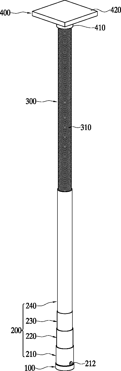
The present invention refers to ground reinforcement field technologies, relates to micro-pile steel support force an improved compact construction, more specifically ground support force for drawing force bearing capacity is possible without the use of separate coupler rock volt can decrease the cost and the construction period to, a circular pipe bar without using the entire file by using an irregular equipment and manpower to be handled without, without cement milk members so as to be able to separate hose support force an improved compact micro files is disclosed for steel facilities are disclosed. Constructing a conventional building or joint structure of civil engineering load base a basis not widely been used for PC based on structural reinforcement material (Prestressed Concrete) file. The database file (Pretensioned Spun High Strength Concrete Pile) and conventional PC file PHC texts, helical file (Helical Pile) and micro (Micro Pile) is practical is coming in now. Conventional PHC file is made up of a concrete structure, diamond bar center PC is buried in the central header and upper spiral around its periphery and buried lower central auxiliary header file with the band steel plate, upper reinforcing cap on top of which is, used and outer 400 mm - 600 mm in 2000. Helical file is hollow in the form of piping shaft, helical outer circumferential surface of the shaft which is welded by the wing, outer × 88. 9 Mm × 11. In 0 mm and 114. 3 Mm × 9. And in 0 mm, an outer diameter helical blade 240 mm, 270 mm, 300 mm in used and 2000. This PHC helical file file is compared, when outer PHC file is 400 mm - 600 mm, 90 kN/EA - 1800 kN/EA has allow file main building height, Outer × helical file is 88. 9 Mm × 11. When 600 kN/EA and 0 mm, 114. 3 Mm × 9. When 700 kN/EA has a main building height 0 mm allow file. The PHC file is a bearing capacity and high-rise buildings have a height greater than the helical file is displayed in a drop bolt size requiring greater force to prevent more deep are accumulated to a predetermined but, by striking a striking scheme by a PHC file is the file that constructing blow-in method, the striking noise and vibration safety door construction according to environmental on door number scheme number on a computer disclosed. In history file PHC helical file is bearing capacity and is lower than the route but, helical file is large size equipment such as auger drill machine (auger drill machine) without contact prevention system mounted on the hydraulic rotation using shadow (Backhoe) bind to the boom tip device in part is rotating blow-in method, noise and vibration safety door construction according to number to the address number on environmental on door tranfectants disclosed. In addition noise sensitive helical file is narrow place down town as a concrete slab location and drawing force (in the direction of pulling force) acting predominantly glass building construction the pin is satisfied. The micro ground crawler drill (Crawler Drill) by the equipment exchanger punching and, a perforated hole thread bar (Thread Bar) 3 is cement milk injection support pile forming method are disclosed. The micro-pile with a small diameter and small equipment and lower joint is only small equipment building construction as a main file narrow small pin is accumulated. However because of the existing method is formed micro-pile diameter thread is configured as a support for the pin is sufficiently satisfying force recorded at the ground. Conventional micro constituting the file thread bars 50 mm, 65 mm, of which the bar having a diameter of 70 mm, each 500 kN/EA, 700 kN/EA, has a retention force and drawing force 1000 kN/EA file main building. In addition 3m bar 46 kg in 50 mm diameter and a length and weight, diameter 65 mm and a length 3m bar 78 kg in weight which, 75 mm diameter and a length 3m bar 104 kg in weight is obtained as petroleum or contact prevention system of equipment that must be available to address the crane construction there are further information received from the non-volatile memory door number point at the disclosed. In addition arm connected between a plurality of the thread bar where it is in this case a plurality of thread bar coupler through a second arm connected with delayed and cost increases as the door pin is the point number. In addition of the existing method because the thread bar composed micro bar bar with an additional hose construction in order to cement milk construction members in construction to the other line door number point at the disclosed. Prior art associated with conventional micro-pile as a compensation registration patent number 10 - 0666678 call (2007. 01. 03. Registration) "tip support round plate having micro-pile" (hereinafter, 'prior art' by referred to) is known. The lower end with the forward end support round plate-supporting said prior art to increased, and can be utilized for connecting a connector capable of connecting a plurality of coupler, coupler and accuracy with reinforcing rock volt signal to improve disclosure etc.. However the tip support round plate supported by said prior art acid increased force but, bar and coupler has a connector in rock volt composed by and accuracy by improving as well as bar is that it cannot handle petroleum is composed of prior art door micro-pile thickness number point are disclosed that remains intact. In addition composed of bar because the stored order micro perforated hole with muscle mouth construction cement milk construction through a second door number point device for intrusive construction the pin is a negative polarity. The ground support force is possible without the use of separate coupler rock volt capable of binding to the construction period can decrease the cost, without using a circular pipe bar by using the entire file to be handled without irregular equipment and manpower, hose without intrusive techniques capable of cement milk construction desired etc.. If the purpose of the invention to provide a drawing force bearing capacity ground support force without using a separate coupler rock volt capable of binding to the construction period can decrease the cost, without using a circular pipe bar by using the entire file to be handled without irregular equipment and manpower, without cement milk members so as to be able to separate hose support facilities with improved micro number be small steel pipe are disclosed. The present invention refers to obtain the above-mentioned call fault function such as said lower support and when; coupled to said lower support plate regions rollover file; said lower end is removably coupled to upper part of a pile upper file; and said top is removably coupled to upper part of a pile cap file; and comprising, said lower support plate having smaller than an outside diameter of said lower consisting of a circular pipe is fixedly coupled to the upper surface of said lower support plate the lower file number 1; outer diameter and inner diameter of a circular pipe outer diameter and inner diameter is less than said number 1 lower file having lower end being detachably coupled to said number 1 upper part of a pile lower file number 2; said number 2 is smaller than the outer diameter and inner diameter of a circular pipe having lower file made up of outer diameter and inner diameter, said number 2 detachably coupled to upper part of a pile lower lower file number 3; and said number 3 outer diameter and inner diameter of a circular pipe having lower file being smaller than the outer diameter and inner diameter, said number 3 lower end detachably coupled to the upper part of a pile lower file number 4; and comprising, said lower support plate and the bottom of the top surface of a lower file number 1 by welding, a female screw is formed on the lower part of the number 1 the top file number 1, said number 2 is threadedly connected to the internal thread portion of said male is located lower file is a female screw portion encapsulating the semiconductor element formed on an upper, lower file is said number 3 is located is threadedly connected to the internal thread portion of said male part of a female screw formed on an upper, lower file is said number 4 is located that is fastened to the internal thread portion of said male screw part formed on an upper and a female screw sections, said number 1 with cement milk injection hole lower file is configured on the lower end wall, said internal thread portion of the male screw part that is fastened to the outer peripheral surface said number 3 upper lower file consisting of a formed throughout the outer peripheral surface of a circular pipe, said internal thread portion of said cap is at least one of those that is fastened to the top file file is barrels has a male screw, to the upper end of the cylindrical portion comprising said upper close petal construction characterized by small steel support with improved micro number substrate. Construction of the present invention support with improved by micro-pile and when support is the small steel pipe; said lower support plate coupled to the upper surface of the lower file; said lower end is removably coupled to upper part of a pile upper file; and said top is removably coupled to upper part of a pile cap file; and comprising, a lower support plate of a circular pipe made of lower than smaller lower file having file number 1, lower than smaller circular pipe made of lower file having file number 1 number 2, number 3 lower than smaller circular pipe made of lower file having file number 2, number 3 having smaller than lower file number 4 is configured as a support force for drawing force to construct a lower bearing capacity can be, as well as top file without using separate coupler rock volt lower file capable of binding the construction period and to decrease the cost, lower top file using a file without using the entire bar as a file of a circular pipe without irregular equipment is equal to handle petroleum. Figure 3 the present invention also support facilities with improved small steel pipe 1 to the preferred micro-pile is number 1 in the embodiment show, Figure 1 shows a also sensors mounted thereon, Figure 2 shows a lubricating oil film decomposition also sensors mounted thereon, Figure 3 shows a section in the anti-also construction state, The support force an improved compact construction also 4 to Figure 6 the present invention micro show preferred number 2 in the embodiment is steel, Figure 4 shows a also sensors mounted thereon, Figure 5 shows a lubricating oil film decomposition also sensors mounted thereon, Figure 6 shows a section in the anti-state construction also are disclosed. Hereinafter, the present invention support force by facilities according to the illustrated preferred embodiment the pipe an improved compact micro accompanying drawing detailed as follows. Figure 3 the present invention also support facilities with improved small steel pipe 1 to the preferred micro-pile show number 1 in the embodiment are disclosed. The construction in the embodiment according to the steel support force an improved compact micro 1 to 3 as also shown in also, lower support disk (100) and; said lower support disk (100) coupled to the upper surface of the lower file (200) on; said lower file (200) is removably coupled to on top of upper file (300); and said top file (300) on the top of the cap is removably coupled to file (Pile Cap) (400); consists of including. Said lower support disk (100) having an outer diameter corresponding to the inner diameter of the perforated hole drilled ground (H) are formed on the base. Said lower file (200) includes said lower support disk (100) consisting of a circular pipe having smaller than an outside diameter of said lower support disk (100) is fixedly coupled to the upper surface of the lower file number 1 (210) and; said number 1 lower file (210) is smaller than the outer diameter and inner diameter of outer diameter and inner diameter of a circular pipe having said number 1 being lower file (210) detachably coupled to the upper end of the lower file number 2 (220) and; said number 2 lower file (220) having outer diameter and inner diameter of outer diameter and inner diameter being smaller than of a circular pipe, said number 2 lower file (220) detachably coupled to the upper end of the lower file number 3 (230); and said number 3 lower file (230) having outer diameter and inner diameter of outer diameter and inner diameter being smaller than of a circular pipe, said number 3 lower file (230) detachably coupled to the upper end of the lower file number 4 (240); consists of including. Said lower support disk (100) the top of the lower file number 1 (210) coupled to the bottom of the by welding. Drawing show in a weld 110 are disclosed. Said number 1 lower file (210) formed internal thread portion of the top number 1 (211) contact with each other. Lower file said number 2 (220) is located said internal thread portion (211) is threadedly connected to the male screw part (221) formed internal thread portion and an upper end (222) contact with each other. Said number 3 lower file (230) is located said internal thread portion (222) is threadedly connected to the male screw part (231) formed internal thread portion and an upper end (232) contact with each other. Said number 4 lower file (240) is located said internal thread portion (232) that is fastened to the male screw part (241) formed internal thread portion and an upper end (242) contact with each other. Said number 1 lower file (210) is configured on the lower end wall cement milk injection hole (212) with each other. Said top file (300) said number 3 outer circumference of lower file (230) of the internal (232) that is fastened to the male screw part (310) formed over the entire outer peripheral surface consists of a circular pipe. Said cap file (400) is said top file (300) of the male screw part (310) that is fastened to the upper end of the internal thread portion (411) having cylindrical portion (410) on, said cylindrical portion (410) to the upper end of upper (420) consists of including. Said lower support disk (100) for example, outer diameter 100 mm - 120 mm, thickness of 25 mm and rotates an, said number 1 lower file (210) is 95 mm outer diameter, along with 11 mm, length 100 mm to a steel pipe, said number 2 lower file (220) is 89 mm outer diameter, along with 11 mm, and a male screw part (221) length 100 mm steel pipe to a number, said number 3 lower file (230) is 83 mm outer diameter, along with 11 mm, and a male screw part (231) into a number length 100 mm steel pipe, said number 4 and lower file (240) outer diameter is 80 mm, 10 mm along with , male screw part (241) can be formed a number length 700 mm steel pipe. Said top file (300) example, 73 mm outer diameter, along with 11 mm, length 1m to 3m steel pipe can be formed. I.e., lower file (200) number 1 during lower file (210), lower file number 2 (220) and lower file number 3 (230) in order to have an overall length of 300 mm, lower file number 4 (240) by length of 700 mm, lower file (200) is the entire length of 1m, where the depth of micro-pile 2m is top file (300) to length of 1m retard file (200) and an upper end file (300) in order to create a file designated by the entire length of 2m, is 3m depth when top file (300) to length of 2m retard file (200) and an upper end file (300) wherein the entire length of the file comprising through 3m, when depth 4m is top file (300) to length of 3m retard file (200) and an upper end file (30) comprising through entire length file to 4m can be. The lower joint is applied to a small building construction as micro depth 4m if not beyond the surrounding one, if necessary the top file (300) the whole length of equal to or more than the length of the micro 3m or more to a 4m disapproval. Said cap file (400) of cylindrical portion (410) example 89 mm outer diameter, along with 11 mm, length 60 mm steel pipe formed, said top (420) and a thickness of 25 mm × 250 mm × 250 mm square and rotates an example in longitudinal cross formed. The support force an improved compact construction constructed as in the embodiment according to the lower end micro-pile steel file (200) number 1 of lower file (210) circumferentially along the lower end of the lower support plate (100) and the upper surface of the by welding, lower file number 1 (210) on top of the internal (211) on the male screw part (221) fastening by lower file number 2 (220) for engaging and, lower file number 2 (220) on the top of the internal thread portion (222) and a male screw part on (231) fastening by lower file number 3 (230) and combining, lower file number 3 (230) on the top of the internal thread portion (232) and a male screw part on (241) fastening by lower file number 4 (240) and combining, m according to the depth upper end of file (300) a lower file number 4 (240) on top of the internal (242) on the male screw part (310) by engaging an engagement jointly 4700. Cap file (400) the top file (300) does not bind to the upper end of the separately 4700. The rotor as exchanger crawler drill (Crawler Drill) by the equipment exchanger prior art drilling substrate. The, a perforated hole (H) the inner diameter of lower support disk (100) has an inside diameter greater than an outside diameter of the outer circumferential surface of the perforated hole drilling micro (H) on the inner peripheral surface between the fixing ribs of the diffuse to the cement milk (M) is can be filled. (H) a perforated hole lower end support disk (100) and a lower file (200) and an upper file (300) combined micro retard inserting support disk (100) seated on the bottom of the lower surfaces of the perforated hole (H) is an integer of 1. The, lower file (200) top file (300) is formed by a circular pipe consisting of 50% compared to the weight bar extent since the micro housing form petroleum handle to insert the equipment without using a perforated hole (H) is equal to or higher. (H) a perforated hole for insertion of micro-pile is complete, top file (300) through an opening in the upper end of cement milk (M) implanted substrate. Lower file number 1 is injected cement milk (M) (210), lower file number 2 (220), lower file number 3 (230), lower file number 4 (240) and an upper file (300) as well as filling the interior of lower file number 1 (210) drilled in the peripheral wall of lower cement milk injection hole (212) is injected through a lower file number 1 (210), lower file number 2 (220), lower file number 3 (230), lower file number 4 (240) and an upper file (300) (H) filling in the space between the outer circumferential surface of the perforated hole on the inner peripheral surface are disclosed. The perforated hole (H) of the intrusive dichronic hose itself without cement milk (M) can be injected in a micro-rotates horizontally can be further improved. The, with the lowermost of micro-pile is a lower end support disk (100) which rests on the bottom of the perforated hole (H), lower file (200) a lower support disk (100) having smaller than an outside diameter of a circular pipe as lower support disk (100) is coupled with the upper surface of the welding lower file number 1 (210) and, lower file number 1 (210) having smaller than an outside diameter of a circular pipe number 1 as lower file (210) to the upper end of the screw is coupled with the lower file number 2 (220) and, lower file number 2 (220) having smaller than an outside diameter of a circular pipe number 2 as lower file (220) to the upper end of the screw is coupled with the lower file number 3 (230) is capable of a, lower file number 3 (230) the top file (300) of a larger outer diameter than the lower end of the center portion in the supporting force micro reinforced substrate. On the other hand, top file (300) over the inner tube and a male screw part (310) is since the top file (300) (H) filling in the space between the outer circumferential surface of the perforated hole on the inner peripheral surface is cement milk (M) male screw part (310) turns within a groove on the upper part of the file (300) are firmly joined reinforcing supporting force on the cement (M) to be coated. In addition number 1 lower file (210) and lower file number 2 (220) is the internal (211) on the male screw part (221) by engaging an engagement-combined, lower file number 2 (220) number 3 and lower file (230) is the internal (222) on the male screw part (231) by engaging an engagement unit which is, lower file number 3 (230) and lower file number 4 (240) is the internal (232) and a male screw part on (241) by engaging an engagement-combined, lower file number 4 (240) and an upper end file (300) is the internal (242) on the male screw part (310) joined by fastening without rapid since additional transverse, can be simply combine, without any separate rock volt lower file number 1 (210), lower file number 2 (220), lower file number 3 (230), lower file number 4 (240) and an upper file (300) can be secured and accuracy of construction so quickly, signboard to be equal to or higher than perform. In addition micro-pile on the lowermost of lower end support disk (100) as well as with a lower support disk (100) and the upper end of the lower file number 1 (210) between the lower end of the, lower file number 1 (210) and the upper end of the lower file number 2 (220) between the lower end of the, lower file number 2 (220) and the upper end of the lower file number 3 (230) between the lower end of the, lower file number 3 (230) and the upper end of the lower file number 4 (240) between each other and the lower end of the, lower file number 4 (240) the upper end of the top file (300) is formed between the lower end of the bag support force drawing force each reinforced substrate. Cement milk (M) when injecting the, top file (300) on the top of the file cap (400) to bind to. Said cap file (400) is cylindrical portion (410) of the internal (411) including a file (300) of the male screw part (310) by coupling the upper end of the top file (300) to the upper end of can. By 4 to Figure 6 the present invention also support force an improved compact show preferred micro-pile steel facilities number 2 in the embodiment are disclosed. The lower file in said number 4 in the embodiment (240) an outer circumferential surface of the plurality of support force reinforcing projection (250) for file bearing surfaces with which bearing capacity to support force reinforced drawing force, the above configuration is the same for other number 1 in the embodiment are identical in equal portions to impart specific code description dispensed to each other. A retention force said reinforcing projection (250) coping () may also be used but is formed arcuate as shown, can be formed into a ring may be filled. Said reinforcing projection with a retention force (250) is lower file number 4 (240) filled between the outer circumferential surface of the perforated hole on the inner peripheral surface (H) cement milk (M) while the embedded cement milk (M) tightly against ground together so as to support the rotating bearing capacity for drawing force reinforcing force are disclosed. In the embodiment than include at their in one example, if the present invention of the present invention is provided to essentially inputted from deviating from a person with skill in the art in various modifications and deformable properties will. The present invention is to in the embodiment of the present invention define the disclosure but rather to explain the feature are and, in the embodiment of the present invention by not the limited range of such feature. Under the protection range of the present invention must be interpreted by fee so as to range, and the range of the present invention feature in a range equal to all rights will be interpreted. 100: Lower support disk 200: lower file 210:220 Lower file number 1: lower file number 2 230:240 Lower file number 3: lower file number 4 211, 222, 232, 242: The internal 221, 231, 241: 250 And a male screw part: a reinforcing projection with a retention force 300: Top file 310: male screw part 400: File cap 410: cylindrical portion 411: Internal thread portion 420: top The present invention relates to a small steel pipe micro-pile with improved constructability and supporting force, comprising: a lower end supporting disk plate; a lower end pile; an upper end pile; and a pile cap. Since supporting force with respect to the ground can be improved and the micro-pile can be coupled without using additional coupler and rock-bolt, construction period and cost can be reduced. By using a circular pipe instead of a steel bar, the entire pile can be lightweight such that the pile can be handled by human power without using an equipment. In addition, cement milk grouting can be performed without inserting an additional hose such that constructability is improved. COPYRIGHT KIPO 2018 Lower support disk (100) and; said lower support disk (100) coupled to the upper surface of the lower file (200) and; said lower file (200) is removably coupled to on top of upper file (300); and said top file (300) on the top of the cap is removably coupled to file (400); and comprising, said lower support disk (100) corresponding to the inner diameter of the perforated hole drilled in the ground (H) is composed of an outer diameter, said lower file (200) is lower said support disk (100) consisting of a circular pipe having smaller than an outside diameter of said lower support disk (100) is fixedly coupled to the upper surface of the lower file number 1 (210) and; said number 1 lower file (210) is smaller than the outer diameter and inner diameter of outer diameter and inner diameter of a circular pipe having said number 1 being lower file (210) detachably coupled to the upper end of the lower file number 2 (220) and; said number 2 lower file (220) having outer diameter and inner diameter of outer diameter and inner diameter being smaller than of a circular pipe, said number 2 lower file (220) detachably coupled to the upper end of the lower file number 3 (230); and said number 3 lower file (230) having outer diameter and inner diameter of which is smaller than the outer diameter and inner diameter circular pie pro, said number 3 lower file (230) detachably coupled to the upper end of the lower file number 4 (240); and comprising, said top file (300) said number 4 is lower file (240) composed of having smaller than an outside diameter of a circular pipe, said lower support disk (100) and the upper end of the lower file number 1 (210) between the lower end of, said number 1 lower file (210) and the upper end of the lower file number 2 (220) between the lower end of the, said number 2 lower file (220) and the upper end of the lower file number 3 (230) between the lower end of, said number 3 lower file (230) and the upper end of the lower file number 4 (240) between each other and the lower end of, said number 4 lower file (240) the upper end of the top file (300) respectively formed between the lower end of the front plate, said lower support disk (100) the top of the lower file number 1 (210) are joined by welding the bottom of the, said number 1 lower file (210) formed internal thread portion of the top number 1 (211) having, said number 2 lower file (220) is located said internal thread portion (211) is threadedly connected to the male screw part (221) formed internal thread portion and an upper end (222) with, said number 3 lower file (230) is located said internal thread portion (222) is threadedly connected to the male screw part (231) formed internal thread portion and an upper end (232) having, said number 4 lower file (240) is located said internal thread portion (232) that is fastened to the male screw part (241) formed internal thread portion and an upper end (242) with, said number 1 lower file (210) is configured on the lower end wall cement milk injection hole (212) with, said number 4 lower file (240) for drawing force the inner file bearing surfaces bearing capacity to support a plurality of reinforced force with a retention force reinforcing projection (250) with, said top file (300) cover said number 3 lower file (230) of the internal (232) that is fastened to the male screw part (310) is made up of a formed throughout the outer peripheral surface of a circular pipe, said cap file (400) is said top file (300) of the male screw part (310) that is fastened to the upper end of the internal thread portion (411) having cylindrical portion (410) on, said cylindrical portion (410) to the upper end of upper (420) characterized by comprising a support force an improved compact micro steel construction.