BATTERY MODULE, AND BATTERY PACK AND VEHICLE INCLUDING SAME
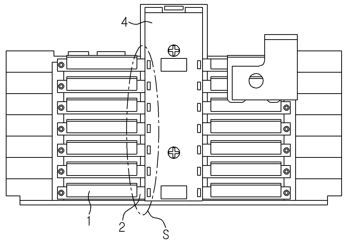
The present invention refers to battery module including battery pack and vehicle relates to, more particularly electrode lead and sensing terminals are altogether to automobiles and battery pack including battery with improved stability of module are disclosed. Notebook recently, video camera, portable electronic devices such as portable showing linear relation between number of the product at each are made abruptly, electric vehicle, energy storage battery, robot, according to the development of satellite formed on the fixing element, repetitive electrical connection etc. studies of high performance secondary battery than the aluminum. The current method for enhancing the secondary battery include nickel cadmium battery, nickel hydrogen battery, nickel zinc battery, lithium secondary battery or the like which, compared to nickel-based secondary battery memory effect occurs in one of the lithium secondary battery has not charge discharge nearly free, compact high energy density is very low discharge rate response disclosed. Such lithium secondary battery is primarily lithium-based oxide and carbon material each cathode active material transmission less than 2000. Lithium secondary battery has, this active material applied electrode plate plate separator between each cathode active material disposed with a electrode assembly, the electrolyte electrode assemblies to prevent material sealed together, a battery case with each other. Generally lithium secondary battery has edge of depending on the shapes of, metal electrode assembly and the can a built-in secondary battery which has aluminum laminate sheet electrode assembly pouch a built-in pouch type secondary cell can be classification. Recent is opened as well as small device such as an electronic device, such as device widely used automobiles power storage device after the completion of welding etc. even secondary battery is provided. In particular, carbon energy is depleted while the walls permits atmospheric glow, U.S., Europe, Japan, including the Korean language by household furniture etc. for electric vehicle and hybrid vehicle portion of concentration. In this hybrid automobiles for electric vehicle battery pack using the force of the core component is most of the motor-driven vehicle are disclosed. Hybrid vehicle or electric vehicle drive force of the vehicle through the certain interval symmetrically of battery pack can be obtained, excellent fuel economy compared to vehicle engine using only vents that are not large users to avoid or reduce gradually spreading a driver or operator are disclosed. And, a plurality of secondary battery wherein the battery pack of electric vehicle this hybrid automobiles, a plurality of such secondary battery in series and connected in parallel on the base and output capacity by each other. On the other hand, in addition to the secondary battery such as battery pack is a BMS (Battery Managememt System) contains various battery pack protection device. This protection device are, battery pack can be safely ensure rich in certain interval symmetrically management plays a role. This protection device are, the gate line and various factor can function, such factor representative of each secondary battery to prevent the voltage can be called. For example, respective secondary battery voltage across value corresponding to the specific protection device can be a driving current to overcharge of secondary battery, secondary battery state-of-charge balanced disapproval function control signals. In this way, battery pack included in protective device wherein at least one of specified functions, each secondary battery included in the battery pack voltage for sensing a essential and very important that be searched because, most of the existing method for detecting these secondary battery voltage battery pack configuration applied in the nanometer range. Figure 1 shows a conventional scheme for the battery module is connected also electrode lead and receptacle shown are disclosed. The reference also 1, battery module has a of the existing method, electrode lead (1) manner of processing such as welding on bus bar (2) on, bus bar (2) physical direction of the bus bar (2) and joined with the receptacle (3) with a module and a structure for sensing voltage. As above-mentioned, receptacle (3) bus bar (2) is in the form of tongs without device along receptacle (3) pressure applied from a combined as only, attach and detach easily disconnected due to pressure exerted from the outside door connection pin is point number. Figure 2 shows a printed circuit board for sensing using the structure shown in the conventional battery module also are disclosed. The reference 2 also, printed circuit board for sensing using the structure of the existing method conventional battery module has a printed circuit board (4) soldering (Solering) region (S) bus bar (2) are allocated to soldering into electrode lead (1) on bus bar (2) voltage sensing structure for processing such as welding is a structure or are anchored into the module and a. The printed circuit board (4) scheme using conventional battery module as described above, bus bar (2) a priori soldering printed circuit board (4) charging module should process for bath in number, printed circuit board (4) bus bar (2) an upper soldering, in the soldering process more frequent on the second voltage detection error occurs at the time the pin is point number door. Figure 3 shows a conventional bus bars are also clamping (Clamping) sensing structure shown the battery module are disclosed. The reference also 3, battery module has a electrode lead of the existing method (1) to (W) weld zone of bus bar (5) and the outer panel bus bar (5) and the electrode lead (1) by electrically connecting, for module and a voltage sensing structure. Then, bus bar (5) extending from an end of a plurality of wires (6) external battery module to the battery module number aligned high pressure liquid coolant therein. This bus bar (5) using conventional sensing scheme for separately battery module has a bus bar (5) and the electrode lead (1) welding and a step for assembling the battery module in a plurality of wires (6) aligning process additionally needed outside as well as a plurality of wires (6) which has a reduced energy density of battery module due to door number point at the disclosed. The present invention refers to electrode lead and sensing terminal with improved stability of electrical connection between the battery module including battery pack and car number to the pin is. In addition, the present invention refers to battery pack voltage sensing terminal electrode lead for sensing only through pressurization assembly process is coupled to the pin is battery module including battery pack and car number. The purpose of the invention referred to above are not one number purposes, another object of the present invention and advantages are not referred to by to the elucidation of can be understanding, of the present invention in the embodiment will clearly less than it will. In addition, the purpose of the invention and advantages are shown and combinations thereof may be realized by means patent claims may allow ready identification are disclosed. To solve said technical and number for the present invention according to the battery module has a plurality of battery cells is provided on the plate-like electrodes and configured in the form of vertically stacked lead, electrode lead that contacts facing in the direction of horizontal between a lead adjacent electrodes as a double-sided type, front side electrode lead at one end having a forwardly projecting protrusion form consisting of a cell assembly and electrically conductive material inserted into are fixed while surrounding projection pressing sensing terminal and sensing terminal supported terminal electronic sensing method and circuit comprise a tray seated. Preferably, the contact electrode lead is connected to electrode lead cell assembly between facing circumferential zone covering the fluidity can be. Preferably, adhesive member can be composed of an electrically conductive material. Preferably, the adhesive member can be between projections disposed between the projections and gluing. Preferably, a lateral projection width electrode lead width implementation being hereinafter the left-right direction. Preferably, sensing terminal contact both sides of the projection and is firmly attached to the contact terminal portion is thin and contact terminals extending from the frame while surrounding projection can be pressing the terminal parts. Preferably, presses the protruding inner contact terminals has the structured surfaces can be set to be lower. Preferably, electrode lead cell assembly located on the side of covering further includes sensing cover can be coupled to the electrode lead. Preferably, sensing cover through the hole is prevented by the projection overhanging direction of projection can be. Preferably, sensing cell assembly opposite to the outer cover part of clothes in the module test sensing on the opposite side can be of a plate. The present invention according to a battery pack can include said battery module can be. The present invention according to the motor vehicle can be said battery module. According to the present invention, capable of enhanced stability of the sensing terminal electrically connected to the electrode lead. In addition, the present invention refers to the soldering process and welding process through the protrusions are electrode lead and sensing terminal kite deficiency without pressurization, number of understanding the process for preparing battery module capable of reducing the reject. Figure 1 shows a conventional scheme for the battery module is connected also electrode lead and receptacle shown are disclosed. Figure 2 shows a printed circuit board for sensing using the structure shown in the conventional battery module also are disclosed. Figure 3 shows a conventional bus bars are also clamping (Clamping) sensing structure shown the battery module are disclosed. Figure 4 shows a dB in the embodiment according to one of the portion of the battery module of the present invention also are disclosed. Figure 5 shows a degradation of the portion of the battery module of the present invention also one in the embodiment according to sensors mounted thereon are disclosed. Figure 6 shows a battery cells shown in the embodiment according to one of the present invention determine the sensors mounted thereon also are disclosed. Figure 7 shows a A shown in the magnified portion of Figure 6 also are disclosed. In the embodiment according to Figure 8 shows a decomposition of one of the present invention test sensing sensors mounted thereon also are disclosed. In the embodiment according to Figure 9 of the present invention engages an engagement one sensing terminal cross-section of the disclosed. Figure 10 shows a part of the processes of the present invention also one in the embodiment according to sensing port surface shown are disclosed. Figure 11 shows a part of the surface of the present invention also other processes shown in the embodiment according to sensing port are disclosed. Figure 12 shows a sensing terminal another in the embodiment according to the front face of the disclosed. Both front, with reference to the attached drawing in detail is carry features and benefits, the present invention is technical idea of the present invention in the embodiment for the person with skill in the art is provided to be hereinafter are disclosed. The present invention is described in the present invention specifically associated with publicly known technique uses the analogy if breach of description is the subject matter of invention description sine wave supplied from a substrate. Hereinafter, the present invention according to preferred embodiment with reference to the attached drawing to explain dilate less than 1000. Drawing indicating the same or similar components to the same references are used. Figure 4 shows a perspective view of the portion of the battery module of the present invention also in the embodiment according to one and, in the embodiment according to Figure 5 of the present invention one dB degradation of the portion of the battery module are disclosed. The reference also 4 and also 5, one in the embodiment according to battery module of the present invention (10) the cell assembly (100), sensing cover (200) and sensing test (300) can be comprising. Said cell assembly (100) includes a battery cell (110) can be comprising. Battery cell (110) can be comprised of a plurality, each battery cell (110) is connected parallel direction (± Y axis direction) can be stacked disclosed. Battery cell (110) does not specifically defined the present invention according to the kind of various secondary cell battery module (10) of cell assembly (100) can be employed in. E.g., said battery cell (110) is, lithium ion battery, lithium polymer battery, nickel cadmium battery, nickel hydrogen battery, nickel zinc battery can be to the substrate. In particular, said battery cell (110) be a lithium secondary battery. On the other hand, battery cell (110) in accordance with the kind of battery pouch type, cylindrical, square or the like can be classification. In particular, the present invention according to battery module (10) battery cell (110) be a pouch type secondary battery. Battery cell (110) when the pouch type secondary battery implemented, also as shown in 4 and 5 also, each battery cell (110) located between the upper and lower polarities are different from each wide, each battery cell (100) can be configured to detect whether the surface is wide facing each other. In addition, in this case, each battery cell (110) arranged to protrude in a horizontal direction (+ X axis direction) can be a lead electrode. Electrode lead anode lead and cathode lead can be composed, and anode electrode assembly is not exposed anode leads, cathode leads can be cathode electrode assembly is not exposed. In hereinafter, with reference to the electrode lead also 6 and 7 also for specifically illustrating the structure of the substrate. Figure 6 shows a perspective view of the present invention shown and also one in the embodiment according to battery cells determine, Figure 7 shows a A shown in the magnified portion of Figure 6 are disclosed. 6 And 7 may also reference surface, electrode lead (111) is inside the horizontal projecting plate (+ X axis direction) can be. In particular, battery cell (110) with electrode lead (111) includes a top layer or underlying layer laminated to different battery cell form bent toward the electrode lead may have. For example, in the configuration of Figure 7 and also 6, 2 stacked one above the other of battery cell (110) with electrode lead (111) (- Z axis direction) 2 located on a left side of electrode lead (111a, 111b) during, positioned under the electrode lead (111a) is horizontal (+ X axis direction, front) ester (+ Y axis direction, + X axis direction) and extending in an annular projecting bracket, again (+ X axis direction) can be configured in the form extending in a horizontal direction. In addition, the left two electrode lead (111a, 111b) positioned on the upper side of the thin plate which (111b) is horizontal (+ X axis direction) ester (- Y axis direction, + X axis direction) extending projecting bracket and an insulating layer, again (+ X axis direction) can be configured in the form extending in a horizontal direction. The, two adjacent electrode lead (111a, 111b) (+ X axis direction) during bending after the horizontal extending section (of Figure 7 A ' portion) can be contact facing each other. Through, a plurality of battery cell (110) are electrically connected constituting cell assembly (of Figure 4 100) can be. On the other hand, two adjacent electrode lead (111a, 111b) of A ' intervals between electrode lead (111a, 111b) for thin joined member (115) can be with. Wherein, joined member (150) lead electrodes (111a, 111b) transmitted electrically connects the conductive material can be composed. Through, joined member (150) lead electrodes (111a, 111b) by electrical connection between upset, thin plate which occur due to external shock and vibration (111a, 111b) can prevent the short circuit between. On the other hand, electrode lead (111) formed by a front side end (shear) (+ X axis direction) at front horizontal form of projection (113) can be formed. Projection (113) lead electrodes (111) to other portions of the thickness can be formed. I.e., electrode lead (111) surface of one (113) generally thickness can be formed. In addition, projections (113) is, the left-right direction (W2) may have a predetermined width. Wherein, the width of the left i.e., ± Z axis can be reference measuring length. More specifically, projections (113) width (W2) left-right direction of the electrode lead (111) the left-right direction width (W1) implementation being hereinafter. And, projection (113) lead electrodes (111) can be formed as a unitary block. On the other hand, projections (113) is formed upward in (± Y axis direction) of electrode lead being extended interconnected 2 (111) can be formed on both. In this case, in a vertical direction to a part of the 2 (± Y axis direction) of the projection (113) far joined member (115) can be with. And, these bonding member (115) is, laminated 2 adjacent one projection (113) can be bonding between. The, press-bonded member (115) through electrode lead (111a, 111b) as well as projections (113) in addition can be electrically connected. The such configuration in the embodiment, press-bonded member (115) is, shear side projection (113) is formed electrode lead (111a, 111b) in a pattern that corresponds to, a portion of the shear side can be configured in the form projecting forwardly thereof. This projection (113) includes a sensing terminal can be a coupling groove. And, such sensing terminal, with sensing terminal module can be. In this way, the present invention according to electrode lead (111) of projections (113) by sensing terminal is directly linked, electrode lead wire to a receptacle or physically connecting the bus bars welded and contains an instability of electrical connection can be blocking. In the above-mentioned protrusion (113) for the sensing terminals connecting it relates diffuse to carry on by. Also 4 and also 5 steps to battery module (10) is described diffuse to other configurations of. Said sensing cover (200) the hook (210), through hole (230) and module loading unit (250) can be a. Sensing cover (200) connects end thereof has a hook (210) which carry the hook portion engaging with the lead cartridge is, cell assembly (100) can be coupled to. Wherein, sensing cover (200) formed electrodes leads cell assembly (100) can be lateral surface of. I.e., sensing cover (200) electrodes lead and lead cartridge (130) to various operation cell assembly (100) coupled to the cell assembly (100) can be lateral surface of. Said through hole (230) the heat exchanger cover (200) on cell assembly (100) is a complementary projection (113) can be at a position corresponding to a position. This, through hole (230) projections (113) overhanging direction of (+ X axis direction) projection part (113) can be penetrated by a. Through, sensing cover (200) cell assembly (100) when coupled, through hole (230) through the projecting portion (113) is penetrate sensing cover (200) can be projecting from. As a result, projections (113) can be combined with the sensing terminal projecting to by sensing terminal. To this end, through hole (230) the depth of projection (113) thereof can made smaller than that. In addition, through hole (230) the number of projections (113) can be corresponds to the number of. For example, as shown in fig. 5, one cell assembly (100) in, projections (113) is, one by one the left-right direction (± X axis direction) include 2, 7 (± Y axis direction) in a vertical direction it into heat, and contacted with total 14 can be. In this case, through hole (230) is, such projections (113) corresponding to the number of and positioning, 2 7 one by one into heat and contacted with total 14 can be. On the other hand, sensing cover (200) includes a cell assembly (100) faces a direction opposite sensing test (300) an end portion of the support plane of the module (250) can be formed. More specifically, an end portion of the module (250) includes a sensing cover (200) sensing on test (300) upon sensing test (300) corresponding to the surface in contact with the shapes can be formed. Through, sensing test (300) the heat exchanger cover (200) from separating from the can be supported. To this end, an end portion of the module (250) on the outer periphery of sensing test (300) sensing when the lift test (300) of guiding its movement guide groove (251) can be formed. More specifically, sensing test (300) on the outer periphery of guide groove (251) to correspond to the projection of (310) can be remaining part, sensing test (300) an end portion of the module (250) upon entering the projections (310) is guide groove (251) can be inserted. Then, guide groove (251) is, inserted X (310) guide movement of, protuberance (310) supporting, an end portion of the module (250) of the sensing test (300) can be smooth to reciprocating. Through, sensing test (300) has separate fixing cell assembly (100) coupled to a sensing cover (200) is calculated only moving process can be simply combined. Next, with reference to the 8 to 10 also may further sensing test (300) for specifically illustrating the substrate. Figure 8 shows a perspective view of the present invention also one in the embodiment according to test sensing and decomposition of, one in the embodiment according to Figure 9 of the present invention engages an engagement sensing terminal cross-sectional drawing which, in the embodiment according to Figure 10 of the present invention processes shown one projection and sensing port surface are disclosed. Sensing test (300) is, said protuberance (310) in addition to the terminal and encapsulating (330) and sensing terminal (350) can be further comprises. Protrusions (310) is as aforementioned, sensing test (300) formed protruded on the outer periphery of the, sensing test (300) an end portion of the module (250) which bind to an end portion of the modules (250) guide grooves (251) inserted into the guide groove (251) can be moves along. In addition, protuberance (310) guide grooves (251) after entry end to guide groove (251) supported from sensing test (300) module loading unit (250) can be fixed. On the other hand, sensing test (300) the heat exchanger cover (200) facing a direction opposite sensing terminal (350) is supported on the outer case to receive the terminal and encapsulating (330) can be formed. More specifically, terminal and encapsulating (330) is sensing terminal (350) and horizontal (± X axis direction) corresponding to the contour of through the holes may be in the form disclosed. Terminal and encapsulating (330) is sensing terminal (350) is embedded and held seated and force sensing terminal (350) to both sensing terminal (350) outside a can be pressed disclosed. Through, sensing terminal (350) to electrode lead (111) a metal end (113) when inserted, projections (113) sensing because of pressure applied from terminal (350) of the terminals and encapsulating (330) can be prevent from detaching from the. Sensing terminal (350) includes a projection (113) is also 10 as shown, a coupling groove at electrode lead (111) can be electrically connected. The sensing terminal (350) lead electrodes (111) is integrally formed projections (113) from making direct contact with the battery cell (110) for sensing voltage because components, made of electrically conductive material can be composed of a metal such as copper or aluminum. On the other hand, sensing terminal (350) includes a projection (113) contact is connected contact terminal portion (351), first lateral surface (351) extending from both sides of the projection (113) while surrounding pressing the terminal portion (353) can be a. First lateral surface (351) has a form which is flat, tablets with a first lateral surface (351) of a protrusion part (113) into which the connection can be. The, first lateral surface (351) pressing the inner surface of the protrusion (351a) is formed projection (113) by pressing, sensing terminal (350) surface of one (113) can be between the back plate and fixing force. On the other hand, pressing terminal portion (353) is also 9 as shown, projections (113) for pressing both sides of each surface encircling the pressing terminal number 1 (353a) and pressing terminal number 2 (353b) can be a. I.e., pressing terminal number 1 (353a) and pressing terminal number 2 (353b) includes a contact terminal part (351) extending from both sides of the projection (113) and deforms while surrounding each side of, the projection (113) is set can be fixed by pressing. In particular, pressing terminal number 1 (353a) and pressing terminal number 2 (353b) is, both sides of the contact terminals can be configured in the form bent into lower direction. And, the bending configuration, pressing terminal number 1 (353a) and pressing terminal number 2 (353b) is, may have elasticity. Furthermore, pressing terminal number 1 (353a) and pressing terminal number 2 (353b) is, first lateral surface (351) between the projection (113) by is placed between, projection (113) can be the lower part of the upper direction. Through, sensing terminal (350) includes a projection (113) surrounding the pressing the terminal portion (353) through the projecting portion (113) which can enhance the female screw fixing force and, in particular the optical unit, can be for example welding apparatus is not work efficiency. I.e., the present invention according to sensing terminal (350) includes a projection (113) contact terminal portion (351) is firmly attached to the contacts on, first lateral surface (351) formed pressing member (351) thus can be fixed. In addition, projections (113) interval of a first lateral surface (351) extending from pressing terminal number 1 (353a) and pressing terminal number 2 (353b) is by pressing sensing terminal (350) projection (113) can firmly fix. 4 And also 5 steps to different configurations of said cell assembly also is described diffuse to the. The reference also 4 and 5 also, said cell assembly (100) includes a lead cartridge (130) can be further comprises. Lead cartridge (130) not be designed between a lead electrodes for physically blocking the electrical connection is provided, in accordance with a separately receiving each electrode lead can be electrically connected. To this end, lead cartridge (130) is formed in the electrode lead electrically connected to individual test method of a semiconductor main size can be. In addition, lead cartridge (130) is inserted into lead electrodes in the above-mentioned protrusion (113) with a shape to project outside through can be horizontal (± X axis direction). The, lead cartridge (130) has a battery cell (110) for coupling with the projection process (113) can be inserted into the inner surface outer surface projecting, facing contact two electrode lead lead cartridge (130) can be housed in a space inside. Through, lead cartridge (130) is to prevent undesirable contact between the electrode lead, can occur to prevent damage to the thin plate which force can be. On the other hand, lead cartridge (130) which carry at one end and one end of each sensing cover (200) of hook (210) are fastened hook portion (131) can be formed. Hook portion (131) is cell assembly (100) on sensing cover (200) is in the fold total hook (210) (- X-axis direction) to the direction opposite to the plugging direction and one of the feet (+ X axis direction), hook (210) to fasten hook (210) connected to sensing cover (200) cell assembly (100) can be associates. Through, cell assembly (100) on sensing cover (200) has connecting direction (- X axis direction) color cover (200) pressing protrusions can be simply combined. Hereinafter, the projections in the embodiment according to of the present invention is described diffuse to the other plural sensing terminal. In the embodiment according to the process of the present invention also other projection and sensing port shown in Figure 11 shows a drawing and, in the embodiment according to Figure 12 engages an engagement other sensing terminal cross-section of the disclosed. The reference also 11 and 12 also, in the embodiment according to of the present invention other projection (113 ') on sensing terminal (350') of the present invention previously described is one in the embodiment according to sensing terminal (of Figure 5 350) on projection (of Figure 5 113) on the same or similar is separably combined refrigerating other configurations without performing the repeated description about the difference in the described substrate. In the embodiment according to of the present invention other projection (113') lead electrodes (111) of the guide (+ X axis direction) is formed in the shape formed by a horizontal, one in the embodiment according to projections (of Figure 5 113) and the electrode lead (111) width (W3) left-right direction of the electrode lead (111) can be equal to the left-right direction width (W1). I.e., in the embodiment according to other projection (113') lead electrodes (111) maintain the same width projecting from an end of the horizontal direction (in the axial direction +) can be in the form. The, in the embodiment according to other projection (113 ') in the embodiment according to projections (of Figure 5 113) coupled to the contrast sensing terminal (350') if the light from the light source contact sensing terminal (350') to enhance stability of the electrical connection with female screw can be. On the other hand, joining members (115 ') in addition projection (113') corresponding to the left-right direction width (W3) projection (113 ') between applied generally to the projection (113') capable of physically bonding and electrically connected thereto. On the other hand, in the embodiment according to other sensing terminal (350 ') includes a projection (113') corresponding to the width of the left and right-and-left direction width (W3) (W4) formed first lateral surface (351 ') on pressing a terminal part (353') can be a. As described above, sensing terminal (350 ') a coupling groove at a electrode lead (111) of projections (113') includes a contact terminal part (351') on can be coupled through surface contact. The, first lateral surface (351 ') adjacent the left-right direction width (W4) (113') the length of the time intervals or the left-right direction width (W3) can be higher than the same. According of the present invention, in the embodiment according to other projection (113 ') in the embodiment according to (of Figure 5 113) coupled to the projection width is wider and, are eliminated to form a crystalline semiconductor, sensing terminal (350') can be yeast such inter-nested and supported. Thus, in this case, electrode lead (111) on sensing terminal (350') between, electrical connection is made more stably maintain the mechanical bearing capacity and can be. On the other hand, in the embodiment according to of the present invention another plurality protrusions can be composed. More specifically, in the embodiment according to the protrusions of the present invention are mutually spaced from another end of the electrode lead horizontal (+ X axis direction) can be formed by a plurality of plate form. For example, in the embodiment according to another to rear protrusions when 3 of the present invention, one end of the electrode lead protrusions, number 1 are mutually spaced from each other end and the center portion comprised of two protrusions, the protrusions can be confronting part number 2 number 3. Through, another in the embodiment according to the protrusions of the present invention sensing terminal (350 ') is formed on the point bonding from receiving, sensing terminal (350') fill and force can be improved. On the other hand, 11 and also of Figure 12 in the embodiment according to said first lateral surface (351 ') is, projections on the inner surface (113') corresponding to the left-right direction width (W3) plurality of 180° in the circumferential (351 'a) is formed projection (113') by pressing, sensing terminal (350 ') surface of one (113') can be between the back plate and fixing force. This also 11 and of Figure 12 in the embodiment according to other sensing terminal (350 ') also, first lateral surface (351') extending from both sides of the projection (113 ') while surrounding pressing the terminal portion (353') can be further comprises. Pressing terminal portion (353 ') includes a contact terminal part (351') extending from two opposite sides of a projection (113 ') encircling the side of pressing for pressing each terminal number 1 (353'a) and pressing terminal number 2 (353' b) can be a. In the embodiment according to number 1 other pressing terminal portion (353 'a) and pressing terminal number 2 (353' b) includes a projection (113 ') mounted to the distal end protrusion (113') corresponding to the left-right direction width (W3) can be in the form of extending. I.e., in the embodiment according to number 1 such pressing terminal portion (353 'a) and pressing terminal number 2 (353' b) is longer and wider width protrusions are each whose scope (113 ') installed to the terminal portions of which are adapted to cooperate with the first and a second (113') polishing direction near the center of projection (113') can be pressing. In this case, pressing terminal number 1 (353 'a) and pressing terminal number 2 (353' b) is, first lateral surface (351 ') on either side of the bent protrusion in each cleaning unit consisting of bending and the shape of the curve (113') near the center of direction, i.e. inwardly extending flat having a drain can be configured in the form. Through, sensing terminal (351 ') surface of one (113') is combined by facing each other present a large area contact electrically connected, as well as physical stability of binding can be to enhance stability of the electrical connection. On the other hand, the present invention according to a battery pack can include, above the battery module comprising one or more. The, battery pack is in addition to the battery module, the battery module for receiving case, battery module of the certain interval symmetrically number for various device, such as BMS (Battery Management System), current sensor, or the like can be further comprises a fuse. In particular, in the embodiment according to one of the present invention battery pack can include, battery module of sensing sensing terminal connecting terminal test seated can be layer is electrically connect to the BMS. The present invention according to the battery module has a, electric vehicle or hybrid such as an automotive vehicle can be option value. I.e., the present invention according to the motor vehicle, the present invention according to battery module can be. The present invention refers to the aforementioned, the present invention is in the field of the present invention is provided within a range that the technical idea from a heavy person with skill in the art to various substituted, deformation and capable of changing the aforementioned in the embodiment and the attached drawing defined by no robbery. 10: Battery module 100: Cell assembly 110: Battery cell 111: Electrode lead 113: Projection 115: Adhesive member 130: Lead cartridge 131: Hook portion 200: Sensing cover 210: Hook 230: Through hole 250: An end portion of the module 251: Guide groove 300: Sensing test 310: Protuberance 330: Terminal and encapsulating 350: Sensing terminal 351: First lateral surface 353: Pressing terminal portion The present invention provides a battery module having improved electric connection stability between an electrode lead and a sensing terminal, and a battery pack and a vehicle including the same. The battery module according to the present invention comprises: a cell assembly composing a plurality of battery cells having the plate-shaped electrode lead which forwardly protrudes in a vertical laminated shape, wherein the electrode lead is composed in a bent shape so as to face each other in a horizontal direction between adjacent electrode leads and the electrode lead provides a protrusion part forwardly protruding from an end of the front direction; and a sensing terminal module having the sensing terminal which is made of an electrically conductive material and surrounds and presses the protrusion part by allowing the protrusion part to be fit and engaged and a terminal mounting hole on which the sensing terminal is mounted and supported. COPYRIGHT KIPO 2018 A lead electrode is provided on the plate a plurality of battery cells and configured in the form of vertically stacked, horizontal direction between a lead facing to contact said electrode lead adjacent electrodes as a double-sided type, projecting forwardly of said front side electrode lead at one end in the form of a protrusion having a coupling groove at said cell assembly and electrically conductive material consisting of protrusions while surrounding said projection for pressing sensing terminal and said sensing terminal part of clothes in the terminal electronic sensing method and circuit including seated causing the battery module. According to Claim 1, said cell assembly includes gluing the lead electrodes facing said contact electrode lead between the adhesive member, said adhesive member electricity conductive material consisting of a battery module. According to Claim 2, it was contiguous said adhesive member disposed between the projections and said projections fluidity battery module. According to Claim 1, the width of said projection in said electrode lead is the left-right direction width hereinafter battery module. According to Claim 1, in close contact with said projections said sensing terminal contact both sides of the contact terminal portion is thin and said contact terminals extending from the frame while surrounding said projection pressing the terminal part including battery module. According to Claim 5, inside surface of the spine of said contact terminals of said pressing method for manufacturing a battery module. According to Claim 1, located on the side of said electrode lead coupled to said electrode lead cell assembly said covering including sensing side of the battery module. According to Claim 7, said projection is prevented by the projection of said sensing cover penetrate said protruding direction is overlapped with each battery module. According to Claim 7, said sensing cover on the opposite side thereof opposite to said cell assembly said test sensing part of clothes in the module unit moves the outer forming a battery module. The battery module in accordance with any one of Claims 1 to Claim 9 including battery pack. In accordance with any one of Claims 1 to Claim 9 vehicle including the battery module.