Systems and methods for optimizing water utility operation
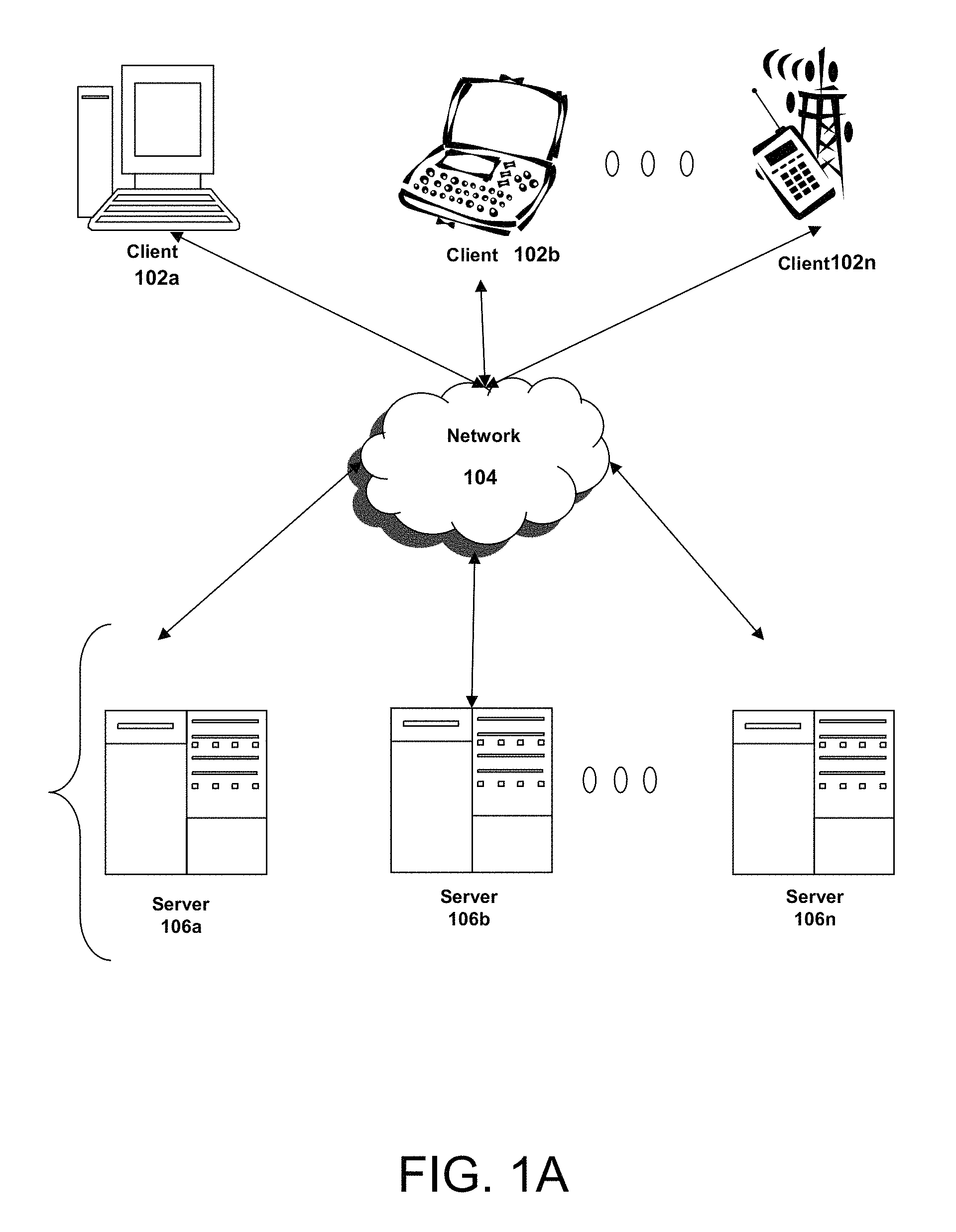
This disclosure generally relates to providing systems and methods for optimizing water utility operation. In particular, this disclosure relates to providing an Internet of Things solution of intelligence, insights, alerts, and recommendations regarding the operation of potable and wastewater pumping stations. Three to Five percent of energy used in the United States is devoted to pumping or otherwise moving water. Pumping systems represent up to seventy percent of this energy. Energy costs represent thirty-five percent of the water production expenses of a water utility. Most pumps waste energy 95% of the time because they are being run inefficiently. This is due in part to a lack of insight into actual operating efficiency of pumping stations. What is needed is a way to manage peak energy consumption without affecting the utility's ability to serve its customers, optimize pumping operations under actual and changing demand requirements, monitor degradation to allow for pro-active and predictive maintenance, avoid emergency repairs, and gain insight on equipment upgrades using real-life data that can be used to justify capital expenditure. The present disclosure relates generally to providing Internet of Things systems and methods for optimizing water utility operation. The systems and methods include providing intelligence, insights, alerts and recommendations for potable and waste water pumping stations. Such insights can provide 5%-30% in energy savings, improve labor efficiencies, reduce operations and management costs via predictive maintenance, avoid catastrophic and emergency repairs, and justify capital upgrades. The systems and methods can leverage existing legacy infrastructure, sensors, and variable frequency drive installations at pumping stations; can be compatible with a variety of SCADA systems; can run without additional hardware installation; can be equipment agnostic with respect to computing platforms, and can provide a single solution for both potable and waste water pumping stations; and can provide an intuitive dashboard providing intelligence and alerts, including droll down into analytical insights. The systems and methods described herein are applicable to, without limitation, both public and private water operators including municipal or public works water departments operated by city, county, state, or federal government. The accompanying drawings are not intended to be drawn to scale. Like reference numbers and designations in the various drawings indicate like elements. For purposes of clarity, not every component may be labeled in every drawing. In the drawings: The features and advantages of the present invention will become more apparent from the detailed description set forth below when taken in conjunction with the drawings, in which like reference characters identify corresponding elements throughout. In the drawings, like reference numbers generally indicate identical, functionally similar, and/or structurally similar elements. Following below are more detailed descriptions of various concepts related to, and implementations of, methods, apparatuses, and systems for optimizing water utility operation using and Internet of Things based Real-Time Intelligence and Big data analytics. The various concepts introduced above and discussed in greater detail below may be implemented in any of numerous ways, as the described concepts are not limited to any particular manner of implementation. Prior to discussing the specifics of embodiments of the systems and methods disclosed herein it may be helpful to discuss the network and computing environments in which such embodiments may be deployed. Referring to Although The network 104 may be any type and/or form of network and may include any of the following: a point-to-point network, a broadcast network, a wide area network, a local area network, a telecommunications network, a data communication network, a computer network, an ATM (Asynchronous Transfer Mode) network, a SONET (Synchronous Optical Network) network, a SDH (Synchronous Digital Hierarchy) network, a wireless network and a wireline network. In some implementations, the network 104 may comprise a wireless link, such as an infrared channel or satellite band. The topology of the network 104 may be a bus, star, or ring network topology. The network 104 may be of any such network topology as known to those ordinarily skilled in the art capable of supporting the operations described herein. The network may comprise mobile telephone networks utilizing any protocol(s) or standard(s) used to communicate among mobile devices, including AMPS, TDMA, CDMA, GSM, GPRS, UMTS, WiMAX, 3G or 4G. In some implementations, different types of data may be transmitted via different protocols. In other implementations, the same types of data may be transmitted via different protocols. In some implementations, the system may include multiple, logically-grouped servers 106. In one of these implementations, the logical group of servers 106 may be referred to as a server farm or a machine farm. In another of these implementations, the servers 106 may be geographically dispersed. In other implementations, a machine farm may be administered as a single entity. In still other implementations, the machine farm includes a plurality of machine farms. The servers 106 within each machine farm can be heterogeneous—one or more of the servers 106 or machines 106 can operate according to one type of operating system platform (e.g., WINDOWS, manufactured by Microsoft Corp. of Redmond, Washington), while one or more of the other servers 106 can operate on according to another type of operating system platform (e.g., Unix or Linux). In one embodiment, servers 106 in the machine farm may be stored in high-density rack systems, along with associated storage systems, and located in an enterprise data center. In this embodiment, consolidating the servers 106 in this way may improve system manageability, data security, the physical security of the system, and system performance by locating servers 106 and high performance storage systems on localized high performance networks. Centralizing the servers 106 and storage systems and coupling them with advanced system management tools allows more efficient use of server resources. The servers 106 of each machine farm do not need to be physically proximate to another server 106 in the same machine farm. Thus, the group of servers 106 logically grouped as a machine farm may be interconnected using a wide-area network (WAN) connection or a metropolitan-area network (MAN) connection. For example, a machine farm may include servers 106 physically located in different continents or different regions of a continent, country, state, city, campus, or room. Data transmission speeds between servers 106 in the machine farm can be increased if the servers 106 are connected using a local-area network (LAN) connection or some form of direct connection. Additionally, a heterogeneous machine farm may include one or more servers 106 operating according to a type of operating system, while one or more other servers 106 execute one or more types of hypervisors rather than operating systems. In these implementations, hypervisors may be used to emulate virtual hardware, partition physical hardware, virtualize physical hardware, and execute virtual machines that provide access to computing environments. Hypervisors may include those manufactured by VMWare, Inc., of Palo Alto, Calif.; the Xen hypervisor, an open source product whose development is overseen by Citrix Systems, Inc.; the Virtual Server or virtual PC hypervisors provided by Microsoft or others. In order to manage a machine farm, at least one aspect of the performance of servers 106 in the machine farm should be monitored. Typically, the load placed on each server 106 or the status of sessions running on each server 106 is monitored. In some implementations, a centralized service may provide management for machine farm. The centralized service may gather and store information about a plurality of servers 106, respond to requests for access to resources hosted by servers 106, and enable the establishment of connections between client machines 102 and servers 106. Management of the machine farm may be de-centralized. For example, one or more servers 106 may comprise components, subsystems and modules to support one or more management services for the machine farm. In one of these implementations, one or more servers 106 provide functionality for management of dynamic and real-time data, including techniques for handling failover, data replication and reliability, and increasing the robustness of the machine farm. Each server 106 may communicate with a persistent store and, in some implementations, with a dynamic store. Server 106 may be a file server, application server, web server, proxy server, appliance, network appliance, gateway, gateway, gateway server, virtualization server, deployment server, SSL VPN server, or firewall. In one embodiment, the server 106 may be referred to as a remote machine or a node. In another embodiment, a plurality of nodes 290 may be in the path between any two communicating servers. In one embodiment, the server 106 provides the functionality of a web server. In another embodiment, the server 106 The client 102 and server 106 may be deployed as and/or executed on any type and form of computing device, such as a computer, network device or appliance capable of communicating on any type and form of network and performing the operations described herein. The central processing unit 121 is any logic circuitry that responds to and processes instructions fetched from the main memory unit 122. In many implementations, the central processing unit 121 is provided by a microprocessor unit, such as: those manufactured by Intel Corporation of Mountain View, Calif.; those manufactured by Motorola Corporation of Schaumburg, Ill.; those manufactured by International Business Machines of White Plains, N.Y.; or those manufactured by Advanced Micro Devices of Sunnyvale, Calif. The computing device 100 may be based on any of these processors, or any other processor capable of operating as described herein. Main memory unit 122 may be one or more memory chips capable of storing data and allowing any storage location to be directly accessed by the microprocessor 121, such as Static random access memory (SRAM), Burst SRAM or SynchBurst SRAM (BSRAM), Dynamic random access memory (DRAM), Fast Page Mode DRAM (FPM DRAM), Enhanced DRAM (EDRAM), Extended Data Output RAM (EDO RAM), Extended Data Output DRAM (EDO DRAM), Burst Extended Data Output DRAM (BEDO DRAM), Enhanced DRAM (EDRAM), synchronous DRAM (SDRAM), JEDEC SRAM, PC100 SDRAM, Double Data Rate SDRAM (DDR SDRAM), Enhanced SDRAM (ESDRAM), SyncLink DRAM (SLDRAM), Direct Rambus DRAM (DRDRAM), Ferroelectric RAM (FRAM), NAND Flash, NOR Flash and Solid State Drives (SSD). The main memory 122 may be based on any of the above described memory chips, or any other available memory chips capable of operating as described herein. In the embodiment shown in A wide variety of I/O devices 130 Referring again to Furthermore, the computing device 100 may include a network interface 118 to interface to the network 104 through a variety of connections including, but not limited to, standard telephone lines, LAN or WAN links (e.g., 802.11, T1, T3, 56 kb, X.25, SNA, DECNET), broadband connections (e.g., ISDN, Frame Relay, ATM, Gigabit Ethernet, Ethernet-over-SONET), wireless connections, or some combination of any or all of the above. Connections can be established using a variety of communication protocols (e.g., TCP/IP, IPX, SPX, NetBIOS, Ethernet, ARCNET, SONET, SDH, Fiber Distributed Data Interface (FDDI), RS232, IEEE 802.11, IEEE 802.11a, IEEE 802.11b, IEEE 802.11g, IEEE 802.11n, CDMA, GSM, WiMax and direct asynchronous connections). In one embodiment, the computing device 100 communicates with other computing devices 100′ via any type and/or form of gateway or tunneling protocol such as Secure Socket Layer (SSL) or Transport Layer Security (TLS), or the Citrix Gateway Protocol manufactured by Citrix Systems, Inc. of Ft. Lauderdale, Fla. The network interface 118 may comprise a built-in network adapter, network interface card, PCMCIA network card, card bus network adapter, wireless network adapter, USB network adapter, modem or any other device suitable for interfacing the computing device 100 to any type of network capable of communication and performing the operations described herein. In some implementations, the computing device 100 may comprise or be connected to multiple display devices 124 In further implementations, an I/O device 130 may be a bridge between the system bus 150 and an external communication bus, such as a USB bus, an Apple Desktop Bus, an RS-232 serial connection, a SCSI bus, a FireWire bus, a FireWire 800 bus, an Ethernet bus, an AppleTalk bus, a Gigabit Ethernet bus, an Asynchronous Transfer Mode bus, a FibreChannel bus, a Serial Attached small computer system interface bus, or a HDMI bus. A computing device 100 of the sort depicted in The computer system 100 can be any workstation, telephone, desktop computer, laptop or notebook computer, server, handheld computer, mobile telephone or other portable telecommunications device, media playing device, a gaming system, mobile computing device, or any other type and/or form of computing, telecommunications or media device that is capable of communication. The computer system 100 has sufficient processor power and memory capacity to perform the operations described herein. For example, the computer system 100 may comprise a device of the IPAD or IPOD family of devices manufactured by Apple Computer of Cupertino, Calif., a device of the PLAYSTATION family of devices manufactured by the Sony Corporation of Tokyo, Japan, a device of the NINTENDO/Wii family of devices manufactured by Nintendo Co., Ltd., of Kyoto, Japan, or an XBOX device manufactured by the Microsoft Corporation of Redmond, Wash. In some implementations, the computing device 100 may have different processors, operating systems, and input devices consistent with the device. For example, in one embodiment, the computing device 100 is a smart phone, mobile device, tablet or personal digital assistant. In still other implementations, the computing device 100 is an Android-based mobile device, an iPhone smart phone manufactured by Apple Computer of Cupertino, Calif., or a Blackberry handheld or smart phone, such as the devices manufactured by Research In Motion Limited. Moreover, the computing device 100 can be any workstation, desktop computer, laptop or notebook computer, server, handheld computer, mobile telephone, any other computer, or other form of computing or telecommunications device that is capable of communication and that has sufficient processor power and memory capacity to perform the operations described herein. In some implementations, the computing device 100 is a digital audio player. In one of these implementations, the computing device 100 is a tablet such as the Apple IPAD, or a digital audio player such as the Apple IPOD lines of devices, manufactured by Apple Computer of Cupertino, Calif. In another of these implementations, the digital audio player may function as both a portable media player and as a mass storage device. In other implementations, the computing device 100 is a digital audio player such as an MP3 players. In yet other implementations, the computing device 100 is a portable media player or digital audio player supporting file formats including, but not limited to, MP3, WAV, M4A/AAC, WMA Protected AAC, AIFF, Audible audiobook, Apple Lossless audio file formats and .mov, .m4v, and .mp4 MPEG-4 (H.264/MPEG-4 AVC) video file formats. In some implementations, the computing device 100 includes a combination of devices, such as a mobile phone combined with a digital audio player or portable media player. In one of these implementations, the computing device 100 is a smartphone, for example, an iPhone manufactured by Apple Computer, or a Blackberry device, manufactured by Research In Motion Limited. In yet another embodiment, the computing device 100 is a laptop or desktop computer equipped with a web browser and a microphone and speaker system, such as a telephony headset. In these implementations, the computing devices 100 are web-enabled and can receive and initiate phone calls. In some implementations, the status of one or more machines 102, 106 in the network 104 is monitored, generally as part of network management. In one of these implementations, the status of a machine may include an identification of load information (e.g., the number of processes on the machine, CPU and memory utilization), of port information (e.g., the number of available communication ports and the port addresses), or of session status (e.g., the duration and type of processes, and whether a process is active or idle). In another of these implementations, this information may be identified by a plurality of metrics, and the plurality of metrics can be applied at least in part towards decisions in load distribution, network traffic management, and network failure recovery as well as any aspects of operations of the present solution described herein. Aspects of the operating environments and components described above will become apparent in the context of the systems and methods disclosed herein. The water utility plant 210 can consist of any type or combination of water utility such as waste water treatment, potable water treatment, well pump, desalination, or the like. The water utility plant 210 can contain a client device 102 The sensors 220 can include sensors for monitoring various parameters and conditions of the water utility plant 210. The sensors 220 can include sensors for measuring or monitoring Voltage “V,” Current “I,” power factor “PF,” Power “KW”, Motor speed “N,” Discharge flow “F,” Discharge Pressure “P” and water levels on suction side and discharge side (e.g.: overhead storage tanks). The sensors 220 can also include sensors for measuring temperature, torque, and vibration of the pump, or the temperature, viscosity, and density of the water. The controls 230 can include any electrical or mechanical feature of the water utility plant 210 that can be controlled. The controls 230 can include various switches, actuators, solenoids, and motors for operating various types of valves, pumps, drains, gates, doors, covers, sprinklers, etc. The server 106 The server 106 The server 106 The examples of the pump and power module 250 and the well and pump module 260 are not meant to be limiting. The server 106 The water utility headquarters 240 can be a central location where control or monitoring of the water utility plant 210 can be performed. The water utility headquarters 240 need not be remote from the water utility plant 210, and in fact can be co-located. The water utility headquarters 240 can include a client device 102 Avg. GPM for each pump and comparison between pumps Average GPM for the entire station Average flow per hour for the station Avg Station GPM vs Rated Capacity (% utilization) Pump operating states (hours, % of time) Pump operation status Pump turn on/off count (frequency of pump cycling) Average Pump Run Time $MG vs % Operating Time or Total Hours % Time spend at Each of Speeds Speeds vs $MG Average Pump Head by Pump Design pump curve vs real-time operation mashup Efficiency vs % of time and $MG Well level vs $MG Pump head vs $MG Speed vs flow, kw, pressure Weighted Average$ per MG for each Pump KW vs Pressure & Flow & Amps On-Peak Demand Energy consumed on/off peak % Total & Daily KWH/1000 gallons pumped Power factor frequency Total pump run time vs gallons pumped Pump operating frequency (flow, pressure, speeds) Motor load analysis Motor efficiency analysis Pump actual efficiency frequency Pump actual vs designed efficiency frequency Wire to Water efficiency frequency Discharge pressure prediction Well level prediction Well specific capacity analysis and well degradation metric Drawdown analysis Hourly sewer flow vs rain gauge readings System analysis when two or more pumps running simultaneously Station Run Time % Pump efficiency decay analysis Pump sweet sport operation analysis The generic processing can include the step of receiving the data stream at the server 106 The plant specific processing steps can include preparing the data for use for a particular water utility plant 210. The server 106 A unique feature of the system is when pumps are not individually sensored and instead there are system level sensors. Even in aforementioned scenario real-time intelligence can be obtained using formulas and methods described below. The server 106 The dashboard 600 can display the time of use as a measure of on-peak percentage. An analog or digital readout can indicate the percentage of time that the water utility plant 210 operated at peak demand. The dashboard 600 can display the peak demand in kilowatts over a specified viewing period. The dashboard 600 can display the real-time amount of energy, in kilowatt hours, used by the water utility plant 210 to pump 1,000 gallons of water and it can perform analytics for a sliding scale of user specified time horizon. The dashboard 600 can display the KWH per 1,000 Gallons or $/MG for each pump of the water utility plant 210. In the example in The dashboard 600 can display the real-time or user specific time horizon load on each motor of the water utility plant 210. The dashboard 600 can display the motor load as a percentage of the maximum motor load. A motor load that is too high or too low can indicate pumping system performance and demand put on the motor The dashboard 600 can display the real-time or user specified time horizon weighted actual average pump efficiency of each pump of the water utility plant 210. The dashboard 600 can display the pump efficiency as a percentage of a theoretical lossless system, or with reference to a designed peak efficiency. A pump efficiency that is too low can indicate operational adjustments or maintenance that might be required within the water utility plant 210 of one or more pumps. The dashboard 600 can display the wire-to-water efficiency of each pump of the water utility plant 210. The dashboard 600 can display the wire-to-water efficiency as a percentage of a theoretical lossless system, or with reference to a practical peak efficiency. A wire-to-water efficiency that is too low can indicate the need for adjustments within the water utility plant 210 or maintenance of one or more pumps. The dashboard 600 can display the power factor of each motor of the water utility plant 210. A power factor that is too low can indicate poor power efficiency and power delivered by the electric utility is much higher than what is actually being consumed. This could drive electric utilities to work with water utility to help improve their electrical infrastructure The dashboard 600 can display the need for maintenance of each pump of the water utility plant 210. A significant gap between actual efficiency vs designed efficiency at that condition flow, speed and head condition is often a good indicator of wear in the system. The dashboard 600 can display the need for maintenance of each well of the water utility plant 210. Well specific capacity degradation is the metric used to explain the drop in well production and is a good indicator when a well is due for service if its specific capacity falls below a threshold. The dashboard 600 can display the aquifer static level depletion of each well of the water utility plant 210. Static level is measured real-time relative to a certain baseline number (usually the time of well construction or well rehabilitation) to provide real-time intelligence if the well static level has dropped. It is a good indicator of well recharging. The dashboard 600 can display an indicator if each well is within a safe pumping level. This is a measurement of water level with in a well once the pump is turned on and after a certain period of time, and is often a good indicator of whether the pump is operating with sufficient water levels in the well. The dashboard 900 can display the pump run time. The dashboard 900 can display the total run time of each pump of the water utility plant 210 in total hours. In this example, the dashboard reveals that pump 1 has had a much longer service life than pumps 2 through 4. The dashboard 900 can display the cost to pump in dollars per million gallons (“$MG”). For example, the expected range for the water utility plant 210 to pump a million gallons of water may be between $25 and $35 per million gallons. In this example, the dashboard reveals that pump 4 is pumping relatively inexpensively while pump 3 is pumping relatively expensively. The dashboard 900 can display the average flow, in gallons per minute, for each pump of the water utility plant 210. In this example, the dashboard reveals that pump 1, relative to its rated capacity, is well utilized. Pumps 2 to 4, are pumping well below their rated capacity, an indication that the pumps are oversized. The dashboard 900 can display total capacity utilization in terms of percent of firm capacity. The firm capacity can represent the capacity of a single water utility plant 210 or a group of water utility plants 210. The dashboard 900 can display the average daily volume, in millions of gallons per day, of the water utility plant 210 or a group of water utility plants 210. The dashboard 900 can display the pump efficiency of each pump. In this example, the dashboard reveals that pump 1 is operating at 57% efficiency, pump 2 at 61%, etc. The dashboard 900 can display pump performance to design. The pump performance to design metric indicates degree to which a pump is operating off its designed efficiency. It is an indication of pump wear. In this example, the dashboard reveals that pump 4 is deviating from its designed efficiency less than Pump 3. The dashboard 900 can display the pump efficiency decay of each pump. The efficiency decay is an indicator of pump ragging or drawing excess energy for similar demand conditions. In this example, Pump 2-4 are experiencing efficiency which is warning and alert to an operator that maintenance of these pumps may be required. The dashboard 900 can display the power factor of each motor of the water utility plant 210. A power factor that is too low is an indication of low power efficiency of these mechanical systems and draws alerts and attention to the operators. The dashboard 900 can display the daily pumping energy of the water utility plant 210. The daily pumping energy can be displayed as an average for the day in kilowatt hours or across user specified date range. The daily pumping energy can also be displayed as a cost of energy for the day. In this example, the water utility plant 210 used 3,934 KWH at a total cost of $423. The AQUASIGHT Data Streamer application can retrieve data by connecting to SCADA controller servers via drivers built into the Data Streamer application. The Data Streamer passively collects from SCADA systems. The Data Streamer communicates independently with the open platform communications (“OPC”) server. The data can be retrieved at a user defined interval and stored on the local client PC into a CSV file or send in a JSON or other data format through an API. The AQUASIGHT Data Streamer can remain running on the client PC and can be password protected against accidental termination. At an interval separate to the collection interval, the local CSV file can be sent to the AQUASIGHT server via FTPS. FTPS is a file transfer protocol that enables SSL encryption of communication. The private key can be stored on the AQUASIGHT server and public key transmitted to FTP clients during an FTP session for the encryption of data. The AQUASIGHT firewall can permit only FTPS traffic and directs that traffic to the FTP service, which handles authentication. The FTP server can be configured with user isolation to control which logged-in FTP users have access to which physical storage. This isolation can segregate client data and prevent unauthorized access into folders not belonging to the client. Client-side firewalls can be configured to have inbound traffic restricted to TCP port 990 (control channel) and only coming from the AQUASIGHT server to prevent unauthorized use of that port. If outbound traffic is restricted, then TCP ports 990 (control channel) and 5000-6000 (data channel range) must be permitted out to the AQUASIGHT server. A completely locked down client-side firewall can be configured as shown in the table 1401. The client-side firewall can be configured to deny all access, inside or outside, via any source or destination ports. The client-side firewall can be configured with a small number of exceptions to permit transmission of data to and from the AQUASIGHT server and the PC running the Data Streamer application via the appropriate ports. To create the digital model, sensor data from the pumping station can be retrieved and processed to generate a mathematical model that behaves in a manner similar to (and in some cases identical to) the mechanical, electrical, and hydraulic components of the physical pumping station. For example, sensor data relating to the number and type of pumps present in the physical pumping station, the speed and position of valves in the pumping station, and water levels for the pumping station can be used to generate the model. In some implementations, the model can be adjusted over time as new sensor data becomes available. For example, machine learning techniques can be applied to new sensor data to generate an improved digital model that more accurately mimics the physical pumping station over time. In some implementations, the characteristics of the model can be used along with one or more non-linear programming constrained optimization algorithms, such as a generalized reduced gradient algorithm or evolutionary programming, to provide settings for an operator of the pumping station to improve the performance of the pumping station. Constraints taken into account by such techniques can include pump runtime, groundwater withdrawal limits, a desired motor load, a desired maximum speed or frequency at which pump combinations may change, a number of pump starts and stops per day, a lower speed limit or valve level, and a minimum tank level. Based on these constraints, the model can serve as a real-time advisor to the pumping station operator by providing the equipment settings that most efficiently accomplish the requirements of the pumping station subject to the constraints. Thus, the model can provide a “best recipe” of settings based on the existing pump design and system operation for various discharge flow and discharge pressure combinations. In the example shown in In some other implementations, the model may server as a historical advisor to provide insight into lost opportunity at the pumping station. For example, the model may be used to determine the optimal input settings over a previous time period (e.g., a day or a week), and may compare the actual pumping station performance to the performance that could have been achieved using the optimal settings. As shown, the interface 2300 may be displayed in a web browser application. However, it should be noted that in other implementations, the interface 2300 may instead be displayed in a different type of application on any form of computing device, such as a smartphone, a tablet computing device, a laptop computing device, or a desktop computing device. In some implementations, the application that generates or displays the information presented in Having now described some illustrative implementations, it is apparent that the foregoing is illustrative and not limiting, having been presented by way of example. In particular, although many of the examples presented herein involve specific combinations of method acts or system elements, those acts and those elements may be combined in other ways to accomplish the same objectives. Acts, elements and features discussed in connection with one implementation are not intended to be excluded from a similar role in other implementations or implementations. For example, although the systems and methods described herein may be described generally with an agent and native contact application, these systems and methods may be implemented by an application, such as a non-native application or the native application itself. In one implementation, the native contact app may include any of the implementations of the agent described herein. In another implementation, the agent may provide the functionality of a contacts application (native or non-native) and update the agent's contact database instead of another application, such as the native contact application. The phraseology and terminology used herein is for the purpose of description and should not be presses a button “involving” “characterized by” “characterized in that” and variations thereof herein, is meant to encompass the items listed thereafter, equivalents thereof, and additional items, as well as alternate implementations consisting of the items listed thereafter exclusively. In one implementation, the systems and methods described herein consist of one, each combination of more than one, or all of the described elements, acts, or components. Any references to implementations or elements or acts of the systems and methods herein referred to in the singular may also embrace implementations including a plurality of these elements, and any references in plural to any implementation or element or act herein may also embrace implementations including only a single element. References in the singular or plural form are not intended to limit the presently disclosed systems or methods, their components, acts, or elements to single or plural configurations. References to any act or element being based on any information, act or element may include implementations where the act or element is based at least in part on any information, act, or element. Any implementation disclosed herein may be combined with any other implementation or embodiment, and references to “an implementation,” “some implementations,” “an alternate implementation,” “various implementations,” “one implementation” or the like are not necessarily mutually exclusive and are intended to indicate that a particular feature, structure, or characteristic described in connection with the implementation may be included in at least one implementation or embodiment. Such terms as used herein are not necessarily all referring to the same implementation. Any implementation may be combined with any other implementation, inclusively or exclusively, in any manner consistent with the aspects and implementations disclosed herein. References to “or” may be construed as inclusive so that any terms described using “or” may indicate any of a single, more than one, and all of the described terms. Where technical features in the drawings, detailed description or any claim are followed by reference signs, the reference signs have been included to increase the intelligibility of the drawings, detailed description, and claims. Accordingly, neither the reference signs nor their absence have any limiting effect on the scope of any claim elements. The systems and methods described herein may be embodied in other specific forms without departing from the characteristics thereof. The foregoing implementations are illustrative rather than limiting of the described systems and methods. Scope of the systems and methods described herein is thus indicated by the appended claims, rather than the foregoing description, and changes that come within the meaning and range of equivalency of the claims are embraced therein. This disclosure provides systems and methods for improving the performance of a water pumping station. A server can be configured to receive data from a plurality of sensors included within the water utility plant. The server can cleanse the data received from the water utility plant to generate cleansed data. The server can prepare the cleansed data for use by the water utility plant to generate plant-specific data. The server also can generate real-time analytic data based on the plant-specific data. 1. A method for improving the performance of a water pumping station, comprising:
receiving, by a server from a water utility plant, data from a plurality of sensors included within the water utility plant; cleansing, by the server, the data received from the water utility plant to generate cleansed data; preparing, by the server, the cleansed data for use by the water utility plant to generate plant-specific data; and generating, by the server, real-time analytic data based on the plant-specific data. 2. The method of 3. The method of 4. The method of 5. The method of 6. The method of 7. The method of 8. The method of generating, by the server, a graph based on the real-time analytic data; and displaying, by the server, the graph on the display screen. 9. The method of 10. A system for improving the performance of a water pumping station, comprising:
a server comprising one or more hardware processors coupled with a memory, the server communicatively coupled to a water utility plant, wherein the one or more hardware processors of the server are programmed with instructions to:
receive, from the water utility plant, data from a plurality of sensors included within the water utility plant; cleanse the data received from the water utility plant to generate cleansed data; prepare the cleansed data for use by the water utility plant to generate plant-specific data; and generate real-time analytic data based on the plant-specific data. 11. The system of 12. The system of 13. The system of 14. The system of 15. The system of 16. The system of 17. The system of generating a graph based on the real-time analytic data; and displaying the graph on the display screen. 18. The system of FIELD OF THE DISCLOSURE
BACKGROUND
SUMMARY
BRIEF DESCRIPTION OF THE DRAWINGS
DETAILED DESCRIPTION


CPC - классификация
CC0C02C02FC02F1C02F1/C02F1/0C02F1/00C02F1/008C02F2C02F22C02F220C02F2201C02F2201/C02F2201/0C02F2201/00C02F2201/4C02F2201/46C02F2201/461C02F2201/4612C02F2203C02F2203/C02F2203/0C02F2203/00C02F2209C02F2209/C02F2209/0C02F2209/00C02F2209/008C02F23C02F230C02F2301C02F2301/C02F2301/0C02F2301/00C02F2303C02F2303/C02F2303/1C02F2303/14GG0G05G05BG05B1G05B13G05B13/G05B13/0G05B13/02G05B15G05B15/G05B15/0G05B15/02G05B19G05B19/G05B19/0G05B19/04G05B2G05B22G05B221G05B2219G05B2219/G05B2219/2G05B2219/26G05B2219/260G05B2219/2605G05B23G05B23/G05B23/0G05B23/02G05B23/028G05B23/0283IPC - классификация
CC0C02C02FC02F1C02F1/C02F1/0C02F1/00GG0G05G05BG05B1G05B13G05B13/G05B13/0G05B13/02G05B15G05B15/G05B15/0G05B15/02G05B19G05B19/G05B19/0G05B19/04G05B2G05B23G05B23/G05B23/0G05B23/02Цитирование НПИ
204/403.03702/188
Reynolds, Laurie, “Technically Speaking: Water and Internet of Things” Jun. 2, 2015 (Year: 2015).
Zhang, Lifang, “Design of Agricultural Environmental Parameters Monitoring System based on Internet of Things” Oct. 1, 2014, Applied Mechanics and Materials, vols. 608-609, pp. 1115-1119. (Year: 2014).