Mounting bracket for an electro-hydraulic control unit
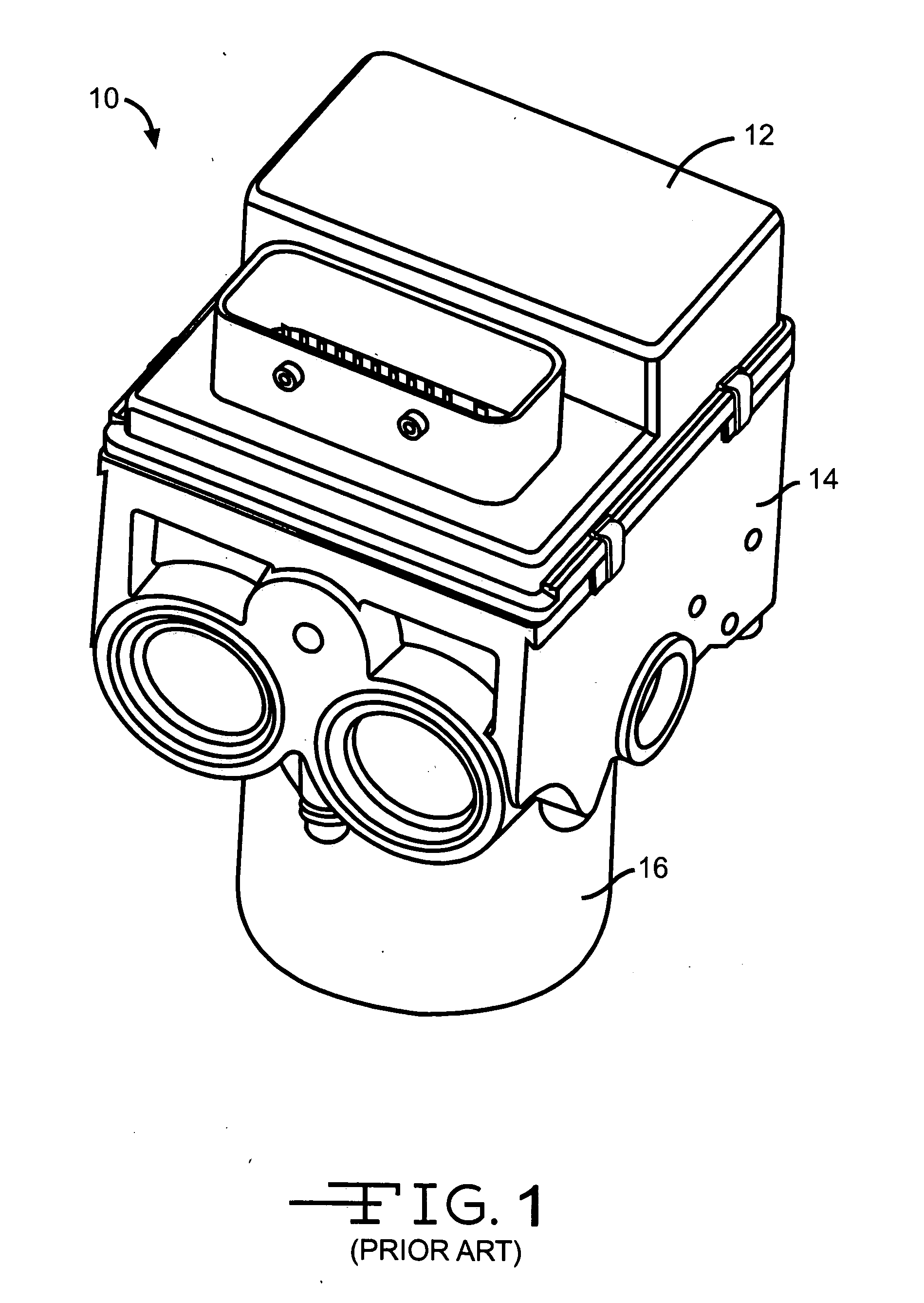
[0001] This application is a continuation of co-pending International Patent Application No. PCT/US02/23 135 filed Jul. 19, 2002 claiming priority to U.S. Provisional Patent Application No. 60/306,641 filed Jul. 19, 2001. International Patent Application No. PCT/US02/23135 was published as WO 03/008245 on Jan. 30 2003 in English under PCT Article 21(2). [0002] This invention relates in general to electro-hydraulic control units and in particular to a mounting bracket for attaching an electro-hydraulic control unit to a vehicle. [0003] Many vehicles being currently produced by automotive manufacturers include automatic brake control systems that are integrated with their hydraulic brake systems. Such systems include Anti-lock Brake Systems (ABS) that prevent wheel lock-up during braking cycles, Vehicle Stability Control (VSC) systems that assist in preventing loss of directional control of a vehicle during vehicle maneuvers and Traction Control (TC) systems to prevent slippage of driven wheels on low mu surfaces, as encountered with icy road surfaces. Additionally, such systems also assist in preventing loss of directional control when the vehicle is operated upon normal or even high mu surfaces, as can occur during accident avoidance maneuvers. [0004] An automatic brake control system typically includes an electro-hydraulic control unit that is integrated with the brake lines of the hydraulic brake system. Referring now to the drawings, there is shown in [0005] The ECU 12 includes a microprocessor and control algorithm for operating the brake system. A plurality of solenoid valves are disposed within the hydraulic valve body 14. The solenoid valves can include normally open isolation valves and normally closed dump valves. The ECU 12 is connected to the solenoid valves and one or more wheel speed sensors (not shown). A pump 16 also is mounted upon the hydraulic valve body 14 to supply pressurized brake fluid to the brake control system. The pump is controlled by the ECU microprocessor. [0006] During vehicle operation, the ECU microprocessor continuously receives speed signals from the wheel speed sensors. When the microprocessor senses an impending vehicle control problem, the brake control system is activated. The ECU microprocessor starts the pump to supply pressurized brake fluid and causes the solenoid valves to cyclically apply and relieve hydraulic pressure to the wheel brakes to correct the vehicle control problem. [0007] The electro-hydraulic control unit 10 is typically mounted within the vehicle engine compartment or upon the vehicle chassis to allow connection of the vehicle's hydraulic brake lines to the hydraulic valve body 14. However, the available engine compartment or chassis surfaces may not be compatible with the needed orientation of the control unit 10 for connection to the brake lines. Accordingly, the electro-hydraulic control unit is 10 usually secured to a mounting bracket that is shaped to align the ports in the hydraulic valve body 14 with the ends of the vehicle's hydraulic brake lines. The mounting bracket is then attached to the engine compartment or chassis surface. [0008] This invention relates to a mounting bracket for attaching an electro-hydraulic control unit to a vehicle. [0009] Typical prior art mounting brackets are fabricated from a sheet of steel. During fabrication, apertures are punched through the steel sheet. Stamping machines cut the sheet into bracket blanks and hydraulic presses bend the blanks into the desired bracket shape. However, being the resulting brackets may transmit vibrations between the vehicle and the electro-hydraulic control unit. For example, engine and other vehicle vibrations are transmitted through the bracket to the ECU where they may effect some of the components mounted therein. Additionally, noise and vibration generated by movement of the solenoid valve armatures, and by rotation of the motor armature and operation of the pump can be transferred from the electro-hydraulic control unit through the vehicle body to the passenger compartment, where they can be disturbing to the occupants. Accordingly, it would be desirable to provide a mounting bracket that reduces the transmission of vibrations and noise in both directions. [0010] The present invention is directed toward a mounting device for a electro-hydraulic control unit that includes an outer supporting structure formed from a non-resilient material that is adapted to be attached to a vehicle. The device also includes a layer of resilient material disposed within and attached to the outer structure and adapted to be placed adjacent to the control unit whereby the resilient material absorbs vibrations. Additionally, the device may further an inner supporting structure formed from a non-resilient material that is attached to the surface of resilient layer that is opposite from the outer structure. The inner supporting structure adapted to be attached to the electro-hydraulic control unit. [0011] In the preferred embodiment the mounting device is a bracket that is formed from a laminated material that has an inner layer of resilient material, such as rubber, is disposed between two outer layers of steel. Alternately, the bracket may include a single outer layer of steel that is lined by a resilient material, such as rubber. [0012] The invention also contemplates a process for fabricating a mounting device for attaching a control unit to a vehicle that includes providing a sheet of laminated material having at least layer of resilient material bonded to at least one layer of non-resilient material. At least one aperture is punched through the sheet of laminated material. Flat blanks are stamped from the sheet of laminated material, with each of the blanks including at least one of the apertures formed previously. The blanks are then formed into brackets. [0013] Various objects and advantages of this invention will become apparent to those skilled in the art from the following detailed description of the preferred embodiment, when read in light of the accompanying drawings. [0014] [0015] [0016] [0017] [0018] [0019] [0020] [0021] [0022] Referring again to the drawings, there is illustrated in [0023] As illustrated in [0024] It is contemplated that the bracket 20 is formed from a sheet of laminated material conventional processes. For example, apertures can be punched through the sheet and stamping machines utilized to cut the sheet into bracket blanks. The blanks can then be bent over forms into the desired bracket shape with hydraulic presses. Alternately, sheet steel is formed by conventional processes into the outer shell and inner support components. A layer of resilient material is attached to the one of the outer shell and inner support and the other of the outer shell and inner support is then attached to form the bracket. [0025] The inner support 26 has a plurality of apertures 28 formed therethrough. The apertures receive threaded fasteners 30, three of which are shown in [0026] The outer shell 24 has a plurality of mounting tabs 32 that extend therefrom. Apertures (not shown) are formed through the mounting tabs 32 and receive threaded fasteners for attaching the assembled mounting bracket 20 and electro-hydraulic control unit 10 to the vehicle. Alternately, mounting extensions (not shown) may be formed upon the outer shell 24 that extend beyond the control unit 10. Apertures formed through the mounting extensions receive threaded fasteners that attach the assembly to the vehicle. Where necessary, openings 34 (one shown) are provided through the outer shell 24 and the resilient layer 22 to provide access to the threaded fasteners 30 that secure the control unit 10 to the bracket 20. [0027] The inventors have found that the improved bracket 20 provides sufficient damping to attenuate both the transmission of vehicle vibrational noise to the ECU 12 and the transmission of acoustic and vibrational noise from the electro-hydraulic control unit 10 to the vehicle passenger compartment. [0028] While the preferred embodiment of the invention has been illustrated and described as a generally U-shaped bracket 20 that cradles the control unit 10, it will be appreciated that the invention also can be practiced with brackets having different shapes. An alternate embodiment of the invention is illustrated generally at 40 in [0029] A sectional view of the preferred embodiment of the bracket 40 is shown in [0030] Alternately, the bracket 40 may be stamped from a sheet of laminated material with the mounting tabs also formed from laminated material (not shown). While being easier, and thereby less expensive, to fabricate, such a bracket would not provide the same amount of isolation since the fasteners would contact both non-resilient layers. Accordingly, the insulative effect for noise and vibration would be reduced. [0031] Another embodiment of the mounting bracket is shown at 50 in [0032] In the preferred embodiment, the bracket 50 is permanently attached to the control unit 10 by a conventional process, such as with an adhesive bond. Thus, the resilient layer 54 provides complete isolation between the bracket 50 and the control unit 10. Alternately, two or more apertures (not shown) can be formed through the bracket 50 to permit a removable attachment of the bracket 50 to the control unit 10 with threaded fasteners. However, use of threaded fasteners in such a manner may reduce the noise and vibration damping efficiency of the resilient polymer material. [0033] Another alternate embodiment of the invention is illustrated in [0034] In the preferred embodiment, the extended portions 66 and 67 of the inner and outer mounts 64 and 65 are threaded. The inner mount extended portion 66 is screwed into the corresponding bore formed in the control valve body 14, which also is threaded. Each of the extended portions 67 of the outer mounts 65 is then received by an aperture formed in a surface of the vehicle engine compartment and secured with a nut. Alternately, a threaded bore can be formed in one or both of the inner and outer mounts (not shown). The bore in the inner mount would receive a threaded fastener that first passed through an aperture formed through a tab that extends from the control unit 10. Similarly the bore in the outer mount would receive a threaded fastener that passed through an aperture formed through a tab that extends from a surface within the vehicle's engine compartment to secure the assembly upon the vehicle. [0035] While the preferred embodiment of the mounting device 60 has been illustrated with three such devices securing the control unit 10 in [0036] An alternate embodiment of the mounting device illustrated in [0037] While the preferred embodiment has been described and illustrated for a mounting bracket to attach an electro-hydraulic control valve to a vehicle, it will be appreciated that the invention also may be used for other purposes. For example, the bracket also can be utilized to attach an electronic control unit only (not shown) to a vehicle. Such an application would arise with an electric brake system where there is no hydraulic valve body or when the electronic control unit is located separate from the hydraulic valve body. [0038] The present invention also contemplates a process for fabricating a bracket. The process is illustrated by the flow chart in [0039] The principle and mode of operation of this invention have been explained and illustrated in its preferred embodiment. However, it must be understood that this invention may be practiced otherwise than as specifically explained and illustrated without departing from its spirit or scope. A bracket for mounting an electro-hydraulic control unit upon a vehicle comprising a layer of resilient material disposed between a non-resilient inner support and a non-resilient outer shell. 1. A mounting device for a securing a control unit to a vehicle comprising:
an outer supporting structure formed from a non-resilient material that is adapted to be attached to a vehicle; and a layer of resilient material disposed within and attached to said outer structure, said resilient material being adapted to be placed adjacent to the control unit whereby said resilient material absorbs noise and vibrations. 2. The mounting device according to 3. The mounting device according to 4. The mounting device according to 5. The mounting device according to 6. The mounting device according to 7. The mounting device according to 8. The mounting device according to 9. The mounting device according to 10. The mounting device according to 11. The mounting device according to 12. The mounting device according to 13. The mounting device according to 14. The mounting device according to 15. The mounting device according to 16. A control unit for a vehicle comprising:
an outer supporting structure formed from a non-resilient material that is adapted to be attached to a vehicle; a layer of resilient material disposed within and attached to said outer structure; and an electronic control unit for controlling a vehicle system disposed within said layer of resilient material whereby said resilient material absorbs noise and vibrations. 17. The control unit according to 18. The control unit according to 19. A process for fabricating a mounting device for attaching a control unit to a vehicle comprising the steps of:
(a) providing a sheet of laminated material having at least one layer of resilient material bonded to at least one layer of non-resilient material; (b) punching at least one aperture through the sheet of laminated material; (c) stamping at least one flat blank from the sheet of laminated material with the stamped blank including at least one of the apertures formed in step (b); (d) forming the blank into a bracket. 20. The process according to 21. The process according to 22. The process according to CROSS REFERENCE TO RELATED APPLICATION
BACKGROUND OF INVENTION
SUMMARY OF INVENTION
BRIEF DESCRIPTION OF DRAWINGS
DETAILED DESCRIPTION