DEVICE AND METHOD FOR PHOTODYNAMIC THERAPY
The invention relates to an apparatus for photodynamic therapy and/or for destroying or reducing microorganisms. The invention further relates to a method of using such an apparatus for photodynamic therapy and/or for destroying or reducing microorganisms. WO 2005/035058 A1 discloses such an apparatus and a method, comprising an irradiation unit that can be moved by means of a positioning element. The irradiation unit contains several light sources by means of which a photosensitizer applied to the wound area to be treated is activated. The irradiation unit contains a camera by means of which images are taken of the wound area before carrying out, and while carrying out, the therapy. The light sources are designed in the form of a cluster lamp comprising several light-emitting diodes (LEDs) and are fixed in the irradiation unit by means of a cooler. Moreover, distance sensors are provided for monitoring the distance of the irradiation unit from the wound area. Moreover, WO 2004/105 874 A2 discloses an apparatus which contains an irradiation unit having a light source that is notably designed as a laser. Using a light-activatable substance, in particular a dye, the microorganisms are sensitized and/or dyed and destroyed after being irradiated with light having a suitable wavelength and power density. The principle of action of photodynamic therapy (PDT) or antimicrobial photodynamic therapy (aPDT) is based on the physical action of energy transmission to the light-activatable substance, which is also referred to as a photosensitizer, following selective action and/or dyeing of the microorganisms, wherein the energy for the reactions is made available at the cell membrane. The energy generated by means of the light source of the irradiation device is focused on the microorganisms and the equilibrium positions of reactions that occur in the non-irradiated state in the “normal environment” are shifted and, as a consequence, the microorganisms are destroyed. The known apparatus contains an applicator, which can be coupled to the irradiation unit and comprises a light guide, wherein the free end of the applicator is guided as closely as possible to the area to be treated for the purpose of irradiating the same. This apparatus has been successfully applied in particular in dental medicine or in the mouth, jaw or facial areas. The known apparatus cannot be employed unconditionally for treating large-surface-area wounds, for example, or for the field of wound healing, by which is meant, merely by way of example, typical chronic wounds or skin ulcerations, such as wound ulcers which occur in patients that are no longer mobile in the tailbone region (decubitus), lower leg ulcerations caused by varicose veins or vascular obliterations (such as ulcus cruris), skin ulcers that can develop as a result of diabetes, such as diabetic foot syndrome (foot ulcer), or acutely infected wounds such as surgery wounds. Based on this, it is the object of the invention to provide an apparatus and a method for applying photodynamic therapy (PDT), or antimicrobial photodynamic therapy (aPDT), in wound healing, wherein in particular a reliable application and/or a proven microbe killing effect are achieved for a maximum possible wound area in a short time. An effective wound therapy that can be controlled in accordance with the respective circumstances is to be achieved with the lowest apparatus-related cost possible and/or with easy handling and/or with high functional reliability. The apparatus as well as the method should be easy to adapt to the medical and/or therapeutic requirements. The apparatus should be easy to adapt to the various positions on wounds, without major complexity, and it should be easy to adjust. Moreover, the weight of the irradiation unit should be specifiable at the lowest level possible, so that the positioning element can reliably maintain this unit in a position that is adjusted by the person performing the treatment. The mobility of the apparatus should be optimized, and notably a low weight and/or small dimensions should be achieved. Moreover, improved damping with respect to impacts or blows is to be achieved, so as to prevent damage to the light source and/or laser diodes. The apparatus according to the invention and/or the method according to the present invention, or the use of the apparatus, allow a functionally reliable and practical application in the field of wound healing, while offering a simple design and/or easy handling. The therapy system according to the invention for applying PDT or aPDT in wound healing allows a reliable application and/or a proven optimal microbe killing effect in a short time, including, and particularly, for maximum possible wound areas. A dye, in particular a blue dye, and/or HELBO Blue Kutan contained in the photosensitizer is applied to the treatment area and/or the wound to be treated, or parts thereof. A defined time period is specified for the action of the photosensitizer, in particular at least 2 minutes, so that the dye molecules can bind to the microorganisms. Thereafter, excess dye is expediently rinsed off and/or dabbed off, wherein the following procedure is employed: aspirating the excess dye using a swab stick, passing over the therapy area with a swab saturated with physiological salt solution and NaCl, and finally aspirating the residual liquid using another swab stick. Thereupon, exposure to light having a suitable wavelength and energy is carried out. For this purpose, light having a wavelength of approximately 661 nm, a power density of at least 100 mW/cm2and an energy of at least approximately 3-5 J/cm2is preferably provided, and/or this is such that the photosensitizer is activated thus inducing the destruction of the microorganisms. The at least one light source is movably disposed in the irradiation unit by means of a guide element, which is designed in particular as a linear guide, so as to be oriented to at least two different irradiation positions of the wound area. The wound area recorded by means of the camera is shown on a display, and the display further shows a grid, or the grid is superimposed on the camera image of the wound area that is displayed, wherein each field of the grid preferably corresponds to an irradiation field, notably in accordance with the respective positioning of the at least one light source that is disposed in the irradiation unit, by means of the guide element so as to be movable sequentially and/or consecutively from one irradiation field to the next irradiation field. A person performing the treatment can select and/or mark the fields to be irradiated by means of at least one light source. The display is advantageously part of an operating unit, which additionally contains buttons for scanning or generating the image of the wound area and for starting or stopping the irradiation, or other input keys. The operating unit moreover preferably contains display elements for the distance of the irradiation unit from the wound to be treated, or the body part to be treated, this distance being captured by means of distance sensors. The display, together with the buttons and the distance indicator, is preferably integrated in an operating unit, which expediently is disposed on the outside of the irradiation unit and/or designed as a separate unit that is easily accessible to the user. The apparatus and/or the method and/or the therapy system according to the invention notably achieve the following advantages:
The apparatus according to the invention and the method directed to the use thereof allow the PDT to be carried out to reduce pathogenic microbes (aPDT), while being easy to handle and offering high functional reliability, in particular for the treatment of the following skin wounds:
For this purpose, the following components or modules are employed:
The elimination of—amongst others—the pathogenic microbes listed below is indicated and was verified by a clinical pilot study. A typical microbial spectrum in the wounds treated according to the invention comprises the following pathogens: The photosensitizer employed is, in particular, the dye HELBO Blue Kutan, which has already received approval. This dye is a consumable and is packaged in individual doses, which are sufficient for treating wounds having the defined maximum wound area. The name “Helbo” herein refers to the company for which the present invention was made, namely, Helbo Photodynamic Systems GmbH & Co., K.G. The invention will be described in more detail hereafter based on the exemplary embodiments shown in the drawings, without thereby limiting the invention in this respect. The use of the HELBO Wounds system and/or execution of the method is provided for after wound cleaning and before applying a wound dressing. As an alternative, the use and/or execution of the method can be done depending on application studies and application observations. A central part of the apparatus and the method is the configuration of the irradiation head and/or of the irradiation unit 2, notably using laser technology. The following is provided in order to achieve the required power data:
The apparatus is preferably divided into the following five primary modules, the prefixed alphanumerical designations of which are used hereinafter.
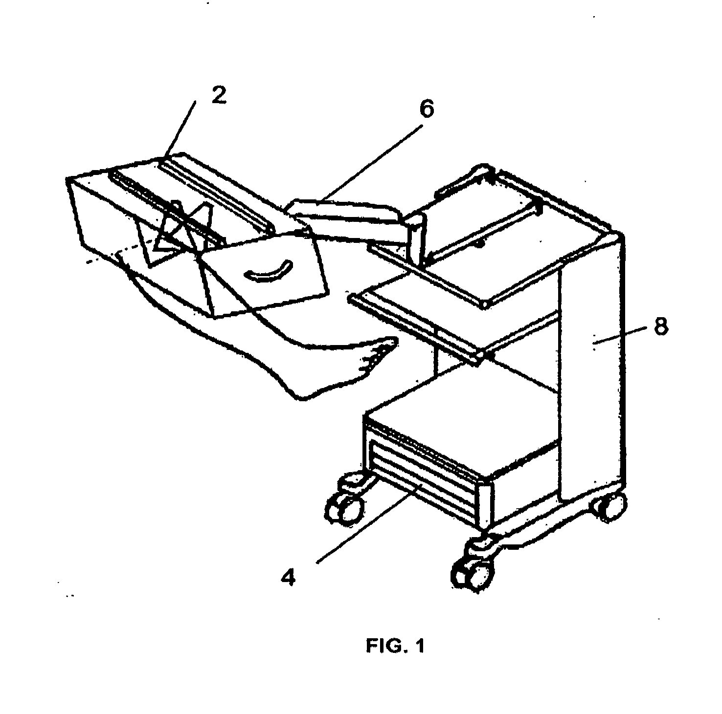
The M1 module—irradiation unit 2—is expediently divided into three sub-modules:
The characteristics and/or functions and/or properties of the modules and components, some of which are formulated hereafter as requirements, and the cooperation of the same are implemented individually or in obvious combinations in the apparatus according to the invention and/or are realized with the method according to the invention. M1A Laser Unit The laser unit 10 notably meets the following requirements:
Interfaces Between M1A and Other Modules:
M1B Control Module: The control module comprises:
Distance Sensors:
Display, Especially Comprising a Touch Screen:
Input Keys:
Start-stop (start/stop irradiation). Preferably a membrane keyboard comprising all the necessary input keys is provided. Moreover, the input keys are optionally integrated in the display. Additionally, the input keys are designed and/or disposed so that a keystroke does not alter the adjusted position of the irradiation unit. Emergency-Off Push Buttons:
Control Software: The control software, for example in the form of an embedded systems, fulfills and/or controls the following functions:
A frame, which bears all the components, in particular linear guide, drives, camera, display, operating elements, sensors, or access protection for diodes.
green: laser is ready (key-operated switch is actuated, device is switched on, and temperature of the laser diode is in the correct range). yellow/orange: for laser emission—start was pressed—device emits light radiation red: error (not absolutely necessary) The indicators either integrated in the display according to relevant standards (EN60825, EN60601-1-22) or designed as dedicated lights (such as LED, LED strips etc.).
Irradiation must not continue automatically after power failure or the like.
The total operating time of the device and the laser operating time of the individual diodes are permanently stored. Interfaces Between M1B and Other Modules:
Space is provided within the irradiation unit for installing the (three) laser diode driver modules, including heat sink/fan (approximate dimensions 120×70×60 mm; installation stationary or on the “laser carriage”).
M1C Irradiation Unit Housing:
Optional: dedicated touch screen (independent of the irradiation unit) comprising dedicated attachment (articulated arm) to the equipment cart.
AKM1C4: housing leakage current is within the boundary values (for example by supplying the irradiation unit with low voltage and applying all relevant sections of EN60601).
M2 Positioning Element Module:
M3 Power Supply Unit Module Including Processor and Safety Elements:
M5 Therapy Set Module: The component referred to as the therapy set comprises the materials required for each individual aPDT application:
The display 20 further comprises a distance indicator 52, which indicates the positioning of the irradiation unit with respect to the wound area 44. If the bars or triangular symbols 54, 55 are all red, for example, the irradiation unit is located too far away at both ends. If, in contrast, the bars or symbols 54, 55 are green, for example, at least in the region of the tips 56, both on the left and right, the irradiation unit is positioned at the correct distance on both sides. The operating unit 14 further contains a scan key 58 and a start/stop key 59. The operating principle of the apparatus and the various steps of the method will be described in more detail hereafter. Step 1: Positioning the Irradiation Unit Over the Wound A Irradiating “long wounds”, wherein the length of the wound in the direction of the longitudinal axis of the irradiation unit and/or the direction of movement is larger than two irradiation areas: The person performing the treatment positions the irradiation unit 20 parallel over the wound area using the aforementioned handles. The two distance sensors are positioned at the ends of the irradiation unit 2, respectively. One distance sensor is preferably disposed on the laser system at the central diode, which is initially positioned at one end of the irradiation unit 2. The second distance sensor is rigidly disposed at the other end of the irradiation unit 2. The two distance sensors measure the respective distance of the plane of movement of the central laser diode from the underlying wound surface or wound area. B Irradiating short wounds, the length of which in the direction of the longitudinal axis is no greater than two selectable irradiation areas. Contrary to variant A, during the adjustment, the distance is measured only at one end of the irradiation unit 2, preferably by means of the distance sensor of the central laser diode. When this distance is correct at one end, the wound can be scanned. Thereafter, it is only possible to select an irradiation area if the distance is correct. It should be noted that during scanning both the camera image and the distance are determined. Irradiation, more specifically by activation of the start/stop key, may only be approved if the correct distance, in particular the ideal distance depicted in green, has been set and the operating temperature of the laser diodes is also in the defined range. Step 2: Orienting the Outer Pivotable Laser Diodes This method step is carried out for the embodiment of the apparatus described in particular based on Step 3: Imaging the Wound Area After the irradiation unit is positioned, the camera integrated in the irradiation unit records an image of the wound, the size of which corresponds at least approximately and/or precisely to the area that may be irradiated. As an alternative, the camera image may be composed of several individual images, wherein preferably several cameras are provided, or a movable camera is provided. As described already in accordance with Step 4: Selecting the Irradiation Area Based on step 3, the grid fields which are to be irradiated are defined, as depicted in Step 5: Starting the Irradiation The irradiation is started by pressing the start/stop key 59 shown in For example, if the irradiation duration per field is 40 seconds, a selected field corresponds to five irradiation positions of, for example, 6 mm. According to the invention, only the fields that have been selected are irradiated. The diode is deactivated for a respective position if the position is not selected. If no field has been selected at a position in the displacement direction, or if none of the three fields that are present next to each other with respect to the travel direction have been selected, the laser unit is immediately moved to the next positions. Step 6: Continuous Distance Control So as to prevent distance changes resulting from movements by the patient or the like during the therapy, according to the invention the distance between the central laser diode and the wound surface is continuously controlled. The distance of the central laser diode is preferably continuously monitored during irradiation of the target area and/or during the linear further movement of the laser unit. If the distance is outside the defined range, the treatment or irradiation is interrupted. As soon as the required distance has been re-established, the therapy can continue following an interruption, in particular by pressing the start/stop key, more specifically starting from the current position. Step 7: End of Therapy Irradiation is terminated when a) all fields have been irradiated; b) the therapy was automatically interrupted due to an incorrect distance and was not continued; c) a maximum total therapy time is reached. This way, the light sources are automatically shut off in the event of an error; d) the start/stop key is pressed after therapy start and before the end of the therapy; and e) the emergency-off push button is pressed. The linear movement of the laser unit is automatically deactivated after all selected fields have been irradiated, wherein preferably audio and/or optical feedback is provided. So as to prevent renewed start-up of irradiation of the wound after the end of therapy by simple and/or inadvertent pressing of the start/stop key, all areas to be treated are deselected after the therapy has ended. Moreover, the start/stop key advantageously has a type of pause function. As long as the predefined distances are maintained, the therapy can be resumed after a stop, or even after an automatic stop resulting from an incorrect distance, by pressing the start/stop key again; the renewed start occurs at the position irradiated last, wherein the irradiation time for this position is restarted. The irradiation time can optionally also be defined or calculated for the renewed start of the aforementioned position, in particular from the remaining time plus a buffer period, which is preferably predefined at least approximately at 5 seconds. The characteristics, properties or operating principles provided hereafter as requirements and criteria for the various components or elements of the apparatus are implemented within the scope of the invention in addition, or as an alternative, to the description provided above, and more specifically individually, or in advantageous combination, in the apparatus according to the invention, or carried out by the method according to the invention. Drive It should be possible to irradiate an area measuring approximately 15×13 cm using three laser diodes. For this purpose, it is required that the diodes be moved by a linear drive. The linear drive is actuated by the real-time system. The two outer diodes are disposed at a fixed angle of 20° (with respect to the irradiation plane or central diode). Color Camera The camera picture depicted should represent an image of the entire area to be irradiated. If it is not possible to depict the area using one image, it is possible to use several cameras or one camera having a linear guide (dedicated or with laser guidance). The camera image that is recorded must be processed by the software of the PC system prior to depiction on the display so as to yield the most authentic depiction of the wound possible (optical control of the recorded image). Additional Light Source If the lighting conditions are insufficient because of the small distance from the wound, a light source is to be provided. The light source is to be activated for the duration of the images (scan). When the start screen is active, the light source is only activated when one of the distance sensors measures a distance of <200 mm (so that the light is only on when the device is used, and not immediately when it is switched on). The light is switched off during irradiation. Distance Sensors The measurement of the distance between the skin and the laser diode should amount to 100 mm (AKM1A4). The measuring accuracy must be at least ±5 mm. It should be possible to change the distance value in the Helbo service menu. Suitable sensors (infrared) must be used for measurement. One distance sensor is to be used for each laser diode, the sensor measuring the distance to the center of the irradiated area (relative to the longitudinal axis of the device). In addition, a sensor is required on the housing. The device is adjusted by means of the sensor on the housing and the sensor on the central laser diode (monitoring and comparison of the measurement result to the actual distance). Display A touch screen measuring at least 8″ must be used to visualize the camera images, to select the areas to be irradiated and for operation. Operation must be possible using disposable gloves. The display and the housing must be protected from moisture penetrating from above (optical control of the camera image, functional check of the touch screen). Input Keys The key-operated switch interrupts the entire power supply of the real-time system and PC system. After being activated by the key-operated switch, the real-time and PC systems start up and the start screen is displayed. This also ensures that irradiation does not automatically start following a power failure. When the device is switched on, the display is switched off when a stand-by key is pressed, and depending on the technical feasibility and usefulness, the PC and real-time systems (=stand-by mode) are also shut off. This mode is indicated by an illuminated red LED (perhaps directly on the push button). Activation from stand-by: by again pressing the stand-by key (if technically possible, also by tapping the touch screen)—all system components are powered up again—the start screen is displayed. A green LED indicates operational readiness (the green LED can be used for this)—the red key LED is then deactivated (or is green). The stand-by key is not effective during irradiation or in the pause mode. After 20 minutes of inactivity (the time configurable), the stand-by mode is automatically activated. The following operating elements are provided on the display and/or touch screen:
starts the recording of the camera image
starts or interrupts the irradiation of the selected fields
interrupts the therapy
Only those operating elements that are allowed to be activated at that time, depending on the therapy flow, can be selected. Operating elements that can be activated are to be highlighted graphically or in color as compared to the non-active elements (such as by a border). All operating elements are to be protected from penetration by liquids. (Confirm the keys and perform functional test). Emergency Off The emergency-off push button stops the real-time system (including all drive motors and laser diodes). The emergency-off push button must be designed in accordance with guidelines (EN 60601-1-22). The remote controllable safety element is treated like an emergency-off push button. If emergency off is actuated, power supply is interrupted to the following components:
Because of the high power consumption of the laser diodes, the power supply is interrupted by a relay. A message is output on the screen indicating that an emergency off was triggered: “Emergency off or external safety circuit was activated. Please check the cause of the interruption and then restart the therapy.” After the emergency-off push button has been deactivated, the system is re-initialized, the message disappears (without actuation by the user) and the start screen is displayed. (Actuate emergency off and door contact switch). Access Guard An access guard is to be provided on the lower face of the device. The laser radiation must be interrupted (pause mode) if anyone reaches into the device during irradiation. The access guard is implemented by the distance sensors. If a distance from an object of less than 80 mm is measured during the continuous measurement (distance from laser diode outlet opening to skin, configurable), all drive motors and laser diodes are stopped. It should be possible to change this distance value in the Helbo service menu. A corresponding warning is shown on the display and the program is switched to pause mode. Laser Operation Indicator The laser operation indicator must comply with the standards EN 60825 and EN 60601-1-22 and can be provided either on the display or by use of LEDs. Three colors should be used for the operation indicator:
laser is operational—key-operated switch is activated, PC and real-time systems are powered up, and laser diodes have the operating temperatures
laser emission
An error has occurred:
Protective laser goggle notice: avoid red symbols and instructional text as much as possible! (Visual inspection of the operation indicator). Storage of Operating Times The operating times of the laser diodes must be documented. It should be possible to reset the stored operating times. (Read operating times after treatment has expired). Control Module The “M1B” control module comprises the control and positioning of the laser diodes. The “M1B” control module is divided into two components:
All safety-critical processes, such as the actuation of the laser diodes, distance measurement, access guard and the like, are managed by this component. The control must be real-time capable.
The PC system manages the processing of the image, the selection of the areas to be irradiated, storing the operating times and user interaction. Interface for Embedded Components The PC system and the real-time system communicate via a serial interface. Communication is assured by a transmission protocol. A “heart beat” is to be defined in the protocol and must be periodically transmitted. If one of the components does not respond, emergency deactivation must be initiated. An error message is shown on the display. (Interrupt communication of the PC system and real-time system, error must be displayed, and the treatment is aborted). Laser Diode Current Monitoring The power consumption of the laser diodes must be monitored during irradiation. If the variance in power consumption exceeds 20%, the treatment must be aborted because the diode may be defective. The power is monitored by an output of the laser controller. EMC, Explosion Protection The EMC standards (EN 60601-1-2) must be taken into consideration when developing the hardware; the explosion protection provisions according to EN 60601-1 are also to be observed. Remote Controllable Safety Element Door contact switches according to standards EN 60825 and EN 60601-1-22. If the switch is actuated (contact is opened), the laser diodes must be deactivated (function similar to emergency off). The electronic circuit for this function is to pass testing in accordance with EN 60601-1 (surge energy capacity). Real-Time System Tasks The real-time system is in charge of
Approval of Irradiation After the irradiation unit is adjusted, the entire length of the irradiation element is traced once so as to measure the distance at each position (the minimum and maximum distances are determined for each selectable area, resulting in information as to whether the area is entirely within the valid range). The valid ranges (8-12 cm distance, it should be possible to change these distance values in the Helbo service menu) are transmitted to the PC system. If the distance is too small, the fields cannot be selected. Distance Measurement The distance must be measured continuously by the real-time system. The sensors for the distance measurement are connected to the real-time system. The distance of each sensor is read several times a second and processed. Deactivation if Distance is too Small If the distance is outside the permitted range <<80 mm or >120 mm, it should be possible to change the distance values in the Helbo service menu—a dedicated set of limits should be provided (not those from the scan)—emergency deactivation of the laser diodes must be performed. The program is interrupted and a message is sent to the PC system. (Reduce distance—deactivation must be performed). Start of Irradiation The irradiation process may not be started until the distance from the wound is in the green range of the area to be irradiated. (Irradiation must not be started if the distance is too small—distance is changed after selection of the areas). Irradiation When starting the irradiation for an area, the laser unit must first be positioned. Then, the laser diode is activated for a certain duration (40 s). The duration is dependent on the power output by the laser diode and it should be possible to change it in the Helbo service menu. When the time for the area to be irradiated has expired, the laser unit is positioned over the next area. The laser diodes should not be deactivated and reactivated during each step (if 2 areas are irradiated consecutively). Areas for which irradiation is not selected are omitted; if no further area exists, the irradiation is properly ended. An area corresponds to 5 irradiation positions in the longitudinal direction (it should be possible to change this value and the travel (6 mm) in the Helbo service menu). The real-time system may only irradiate areas that were selected on the PC system. (Selection of the areas and control of the irradiated areas). End of Therapy When all areas have been irradiated, the laser diodes are deactivated, and the end of the therapy is reported to the PC system. (Wait for end of therapy). Time-Exceeding An area may be irradiated only for a certain period. The time is to be controlled by two systems that are independent of each other (EN 60601-1-22). The time for the laser diode is measured by the real-time system. If the maximum time is exceeded, the diode is deactivated and an error is transmitted to the PC system. In addition, the duration of activation of the laser diode is monitored by a suitable hardware circuit. If the diode is activated for an excessive period of time, the laser diode is deactivated by the hardware. The maximum activation duration for each position is 120 seconds. Pause During Irradiation The PC system may initiate a pause of the irradiation process. When the real-time system receives a pause command, the irradiation is interrupted and the laser diodes are deactivated. When the therapy is continued, the remaining time is increased by 5 seconds (it should be possible to change the value in the Helbo service menu), and the irradiation of the area continues. (Trigger pause, irradiation is correctly continued). Safety Functions A “watchdog” is implemented to prevent program crashes and infinite loops. The program must reset the watchdog at cyclical intervals, otherwise a reset is carried out. To ensure than an area is not irradiated for too long, the hardware performs automatic shut-off after the laser diode has been activated for longer than 120 seconds. The laser diode temperature and the diode current are monitored continuously. If a value is outside the valid range, deactivation takes place so as to prevent damage to the laser diodes. When the door contact switch or emergency-off switch is actuated, the laser diodes must be switched off. If the communication between the PC system and the real-time system is interrupted, the therapy must be aborted. Cooling Each laser diode is cooled by a fan. The speed measurement signal for the fan must be monitored. If a fan fails, the treatment is aborted and an error is reported to the PC system. Operational Readiness Operational readiness is not reported to the PC system until all laser diodes are at the operating temperature and the fans are operational. PC System
Screens/Messages/Audio Notices Screen Displays: 1. welcome screen (optional): off, continue 2. start screen: appears after system start and is used to position the irradiation unit—the live camera image is displayed, overlaid with the distance indicators. Operating elements: back (to the welcome screen), continue (to the therapy screen) 3. therapy screen: the irradiation grid is displayed with the camera image underneath, miniature display of the current distance measurement, progress of irradiation. Operating elements: back (to start screen), scan, start/pause, abort 4. service menu: settings, must not be accessible to the user An audio pause operating element is to be provided on all screens. Languages: German, English—multilingual options should be provided, additional languages should be easy to implement. Service menu only in English. Symbols: All messages should be supported by symbols. Error messages: 2 error categories for messages: a) user or therapy error—for error message see respective REQ b) system or device error, illuminated red error LED, error message: “Device error xxx. Please restart the device. If the error occurs again, please call technical support.” Audio notices: An audio alarm signal should be emitted for each message. Distance Measurement—Graphical Representation The distance measurement data from the real-time system is processed in the PC system, the distance is represented in color and graphically on the display. The colors of the bars are defined as follows (distances configurable in the service menu):
(The color rendering is to be verified using standard-compliant protective laser goggles!) The distance indicator is depicted on 2 different input screens: 1. start screen: adjusting the irradiation unit—the live camera image (unprocessed) is shown (carriage with camera and distance sensor at the end position, on which the fixed distance sensor is not mounted), overlaid with the distance indicators. The distance bars are shown in a transparent fashion because only those bars that represent the currently measured distance are shown in solid colors. 2. therapy screen: miniature display of the current distance measurement (fixed sensor and central distance sensor on the carriage) (optional) Adjusting the irradiation unit: If the irradiation unit is placed over a large wound, the distance at both ends must be in the green range (=distance 9-11 cm, it should be possible to change this distance value in the Helbo service menu). In the case of smaller wounds, it is possible for only one end of the irradiation element to be in the green range. The distance during the adjustment is measured at the central laser diode. During the scan process, the valid ranges are determined (the process can be started when one end of the irradiation element is in the valid range). (comparison of data from the real-time system and the depiction on the display). Camera Image, Grid, Irradiation Area The PC system processes the camera image, which is then shown on the display. A grid is placed over the image. The size of a grid field (in the irradiation region) is: length (in longitudinal device axis): 30 mm (corresponds to 5 irradiation positions @ 6 mm) width: 45 mm The grid consists of a total of 5×3 fields, whereby the entire image covers an area of 150 mm×105-135 mm. The size of a field on the screen is approximately half the original size (15×23 mm W×H)—and in any case, as large as possible. (Compare depiction on the display to wound; fields can only be selected if the distance is OK). Scan When the scan key is actuated, the image information is read and the distance from the wound is measured at each irradiation position. Message: “Scan is complete. Please select the fields to be irradiated.” The areas which, according to the scan, are not within the valid distance range are automatically highlighted with a red X. Irradiation areas should only be selected if the distance to the laser diode from the wound is in the valid range (50-120 mm, in each case measured at the center of the irradiation field for each laser diode; it should be possible to change all distance values of this REQ in the Helbo service menu). This also allows smaller wounds to be irradiated if the distance cannot be maintained over the entire length of the device. However, the user may also select the sub-areas (X) for which irradiation is not valid. Start The PC system can start the irradiation process only if at least one area is selected and the distance from the wound is in the valid range. Prior to starting the irradiation process, a message “Therapy starts—wear protective goggles!” appears (with the goggles symbol) and an audio signal is emitted. Irradiation is started after a delay of 3 seconds, and the message disappears automatically after 10 seconds (configurable). The text of the “Start” button is changed to “Pause”: (Start is only possible if at least one area is selected). Irradiation The areas that have been selected are transmitted to the real-time system. Each selected area is irradiated for 40 seconds. It should be possible to change this duration in the Helbo service menu. Changes to the areas are no longer possible once the program has been started. The ongoing therapy and the irradiated areas are visualized on the display, for example by way of a migrating bar, which represents the laser position. Areas that have already been irradiated should be highlighted in color (different red hue). The remaining irradiation time should be displayed. (Control the laser position and compare to a selected area). Continuous Distance Control If the real-time system reports that distance of a laser diode (applies to all 3) is too small or too great, a notice is shown on the display and the program is switched to the pause mode. The therapy can only be continued when the distance is in the valid range again (80 mm to 120 mm; it should be possible to change the distance value in the Helbo service menu). The monitoring function for the minimum distance is always activated, while for the maximum distance it is only activated when an area was selected for irradiation. End of Therapy The real-time system reports the end of therapy as soon as all areas have been irradiated. The PC system emits an audio message and a visual message. All areas are deselected to prevent renewed irradiation. Text is required on the display for setting forth the message (translations may be required). If the minimum distance was not adhered to (REQ 305) during irradiation, a notice regarding hygiene measures is to also be shown on the display after acknowledging the message “Therapy has ended,” because the patient may have come in contact with the device. This message is to be acknowledged and appears once more before starting the next treatment (after activation, or activation from stand-by). Text: Patient may have come in contact with the device—please clean particularly thoroughly! Time-Exceeding If the real-time system reports a time-exceeding (maximum activation duration of a laser diode), an error is shown on the display, and the current therapy cannot be continued. Text is required on the display for setting forth the error message (translations may be required). “Device error xxx. Please restart the device. If the error occurs again, please call technical support.” Protective laser goggle notice: avoid red symbols and instructional text as much as possible! Pause During Irradiation The current therapy can be paused using a key on the touch screen. The text of the “Pause” button is changed to “Start”: The progress bar is flashing. An information message sweeps over the grid: “Please ensure that the irradiated body part is still positioned correctly; if not, abort the therapy.” The PC system likewise switches to the pause mode if the distance from the wound during irradiation is no longer in the valid range. When the device is pause mode, there are 2 options for continuing: continue the treatment using the start/pause key (distances must be correct again); abort key: (if distances are no longer correct or for other reasons, for example the patient has moved excessively); (interrupt and continue therapy). Abort The current therapy can be aborted using a key on the touch screen. The following scenarios are possible: 1. During irradiation, or 2. In pause mode: query “Therapy is in progress. Are you sure you want to abort?, if aborted: “Therapy has been aborted. Selected area was not fully irradiated!” 3. During display of the therapy screen (same function as “back”) After the process has been aborted, the device is reset to the original state (start screen). (interrupt and continue therapy). Operating Times The following data is stored:
The data can be shown on the display in a service menu. The language used for this menu is English. The service menu is accessed through a special combination on the touch screen. Safety Functions Communication with the real-time system is assured by a transmission protocol. If the connection fails or the real-time system no longer responds, an error is shown on the display. General Requirements The standards EN 60601-1, EN 60625-1 are to be observed when developing the housing. Moreover, the fitness for use in electrical medical equipment according to EN 60601-6 is to be verified and validated. The total weight of the irradiation unit should not exceed 13 kg. Lightweight materials (such as aluminum) should therefore be used. Only components that are absolutely essential should thus be installed in the irradiation unit. Because Of the weight, the PC system should be installed in the equipment cart, with the exception of the touch screen. The housing should be easy to clean; recesses and grooves should be avoided. Housing The following components must be integrated in the housing of the irradiation unit:
The housing must be protected against liquid penetrating from above. Air vents must not be directed at the wound of the patient or at the patient. A cover (transparent polycarbonate (PC) panel, curved (r=240 mm) along the longitudinal device axis, 2 mm thick) is provided on the lower face to prevent damage. Handles for positioning the irradiation unit are required laterally on the housing. The irradiation unit is mounted to the articulated arm. It is accommodated by way of the VESA 75 mount and is to be designed so that a rotational movement of the irradiation unit is possible. The size of the housing is defined by the components that are installed and by the sizes of the linear drive and the lateral guide. The maximum housing leakage current of 0.5 mA as per EN 60601-1 must be adhered to. The materials that are employed should likewise contribute to the EMC shielding of the system. The housing must be protected against penetration by liquid, so as to protect the electronics. Linear Guide It must be possible to move the laser diodes over a length of 15 cm. For this purpose, a suitable drive, such as a stepper motor, comprising an incremental encoder for position determination should be used. The laser diodes must be mounted so that impact is cushioned. Guidance of the Lateral Diodes The lateral laser diodes are rigidly connected to the central diode—at a defined distance. They are pivoted inward by an angle of 20°. The invention relates to an apparatus for photodynamic therapy and/or for destroying or reducing microorganisms, comprising an irradiation unit having at least one light source, by means of which a photosensitizer applied to a wound area to be treated is activated by way of irradiation, further comprising a camera for recording images of the wound, which is disposed in the irradiation unit, and a positioning unit, by means of which the irradiation unit can be oriented with respect to the wound area. The invention further relates to a method for operating such an apparatus. On a display for the images is a grid with visual indicia distinguishing fields to be irradiated by means of the light sources. 1.-10. (canceled) 11. An apparatus for photodynamic therapy or substantially destroying microorganisms at a wound site to which a photosensitizer has been applied, comprising an irradiation unit comprising at least one light for irradiating the wound site, a camera for recording images of the wound site, a display providing a grid on which the images of the wound site are displayed so that the wound site is divided on the display by the grid into a plurality of wound areas, the display also providing visual indicia for differentiating grid areas corresponding to wound areas where irradiation has been completed from wound areas where irradiation has not yet been effected, a drive unit, and a support and guide structure mounting the irradiation unit for moving of the irradiation unit by the drive unit to a plurality of positions so that the light source irradiates the wound site sequentially at each of the grid areas displayed in the display for which the visual indicia indicates that irradiation is to be effected. 12. The apparatus of 13. The apparatus of 14. The apparatus of 15. The apparatus of 16. The apparatus of 17. The apparatus of 18. The apparatus of 19. The apparatus of 20. The apparatus of 21. The apparatus of 22. A method for photodynamic therapy or substantially destroying microorganisms at a wound site to which a photosensitizer has been applied by operating the apparatus of 23. The method of BACKGROUND OF THE INVENTION
SUMMARY OF THE INVENTION
group F Coagulase neg. BRIEF DESCRIPTION OF THE DRAWINGS
DETAILED DESCRIPTION OF THE INVENTION