VERTICAL ARTICULATED ROBOT
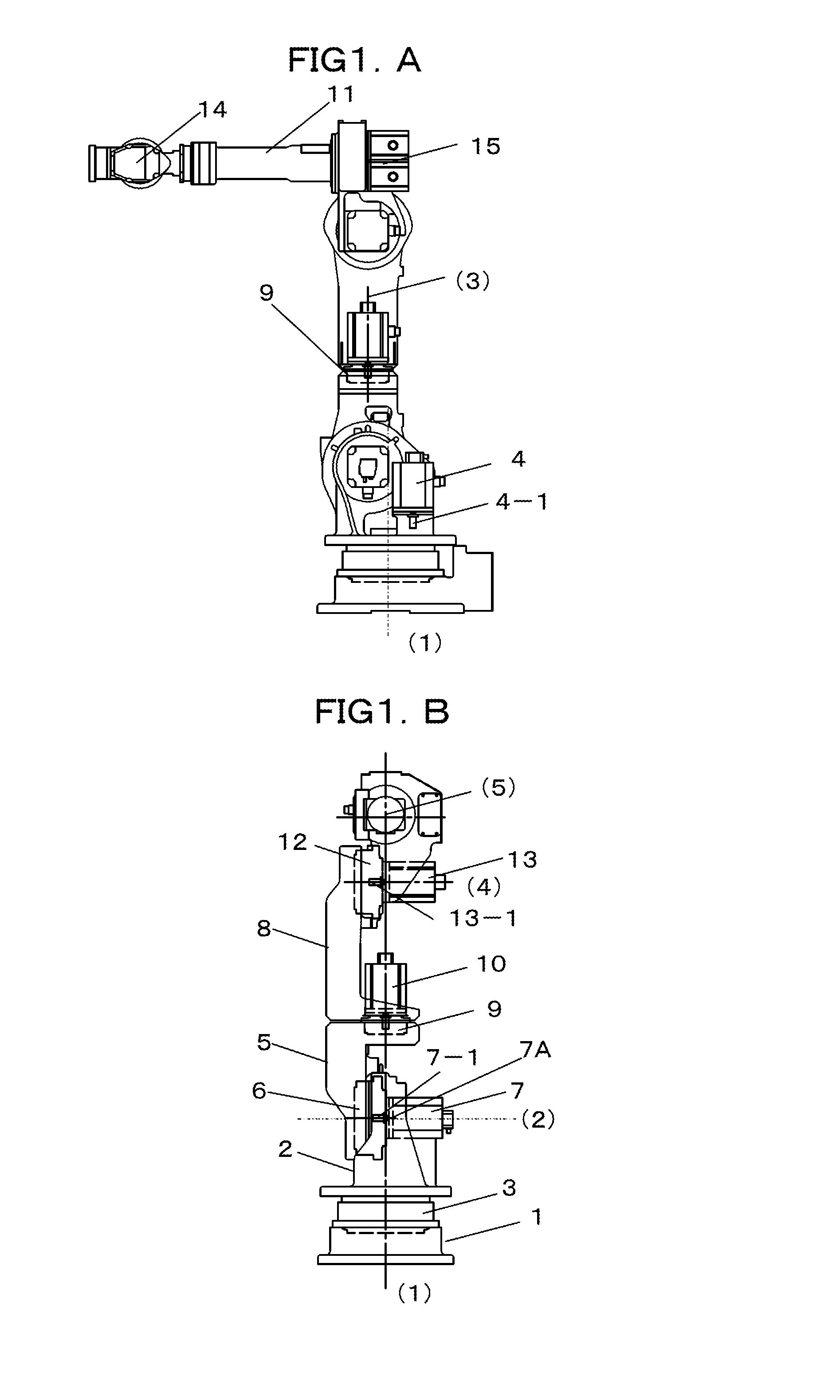
The present application is a divisional application of the U.S. patent application Ser. No. 12/720,677 filed Mar. 10, 2010, which in turn is a continuation application of PCT/JP2008/068627, filed Oct. 15, 2008, which claims priority to Japanese Patent Application No. 2007-305001, filed Nov. 26, 2007, and Japanese Patent Application No. 2008-062522, filed Mar. 12, 2008. The contents of these applications are incorporated herein by reference in their entirety. 1. Field of the Invention The present invention relates to a vertical articulated robot. 2. Discussion of the Background As an example of a vertical articulated robot according to the related art, Japanese Unexamined Patent Application Publication No. 2-298482 discloses a seven-degree-of-freedom robot with which the problem of flexibility can be solved. The seven-degree-of-freedom vertical articulated robot according to the related art is capable of avoiding interference with a workpiece or peripheral devices and interference between arms of the robot, and the operating area around the robot can be effectively utilized. According to one aspect of the present invention, a vertical articulated robot includes a base, a turning base, a first upper arm, a second upper arm, a front arm, a wrist assembly, a first motor, a second motor, a third motor, a fourth motor, and a wire body. The turning base is provided on the base to be rotatable with respect to the base about a first rotation axis. The first upper arm is provided on the turning base to be rotatable with respect to the turning base about a second rotation axis provided along a plane perpendicular to the first rotation axis. The second upper arm is connected to the first upper arm to be rotatable with respect to the first upper arm about a third rotation axis provided along a plane perpendicular to the second rotation axis. The front arm is connected to the second upper arm to be rotatable with respect to the second upper arm about a fourth rotation axis provided along a plane perpendicular to the third rotation axis. The wrist assembly is connected to the front arm. The first motor is to rotate the turning base with respect to the first upper arm about the first rotation axis. The second motor is to rotate the first upper arm with respect to the turning base about the second rotation axis. The third motor is to rotate the second upper arm with respect to the first upper arm about the third rotation axis. The fourth motor is to rotate the front arm with respect to the second upper arm about the fourth rotation axis. The wire body includes a first wire portion, a second wire portion, a third wire portion, a fourth wire portion, a fifth wire portion, and a sixth wire portion. The first wire portion extends from the turning base along the third rotation axis and is connected to an outer surface of the first upper arm. The second wire portion extends from the first wire portion along a plane perpendicular to the third rotation axis and is connected to an outer surface of the first upper arm. The third wire portion extends in a U-shape from the second wire portion. The fourth wire portion extends from the third wire portion along a plane perpendicular to the third rotation axis and is connected to an outer surface of the second upper arm. The fifth wire portion extends from the fourth wire portion along the third rotation axis and is connected to an outer surface of the second upper arm. The sixth wire portion extends from the fifth wire portion and is connected to the front arm. A more complete appreciation of the invention and many of the attendant advantages thereof will be readily obtained as the same becomes better understood by reference to the following detailed description when considered in connection with the accompanying drawings, wherein: Embodiments will now be described with reference to the accompanying drawings, wherein like reference numerals designate corresponding or identical elements throughout the various drawings. A drive motor 7 for a first upper arm 5 is arranged on a second rotation axis (2) in an opening provided in the above-described turning base 2. The second rotation axis (2) is in a plane perpendicular to the first rotation axis (1). An output shaft 7-1 of the drive motor 7 for the first upper arm 5 is connected to an input shaft of a reduction gear 6 for the first upper arm 5. The reduction gear 6 for the first upper arm 5 is secured to both the opening in the turning base 2 and a side surface of the first upper arm 5, and is supported so as to be turnable about the second rotation axis (2). The first upper arm 5 has an inverted L shape such that an L-shaped member is vertically inverted. An upper end portion of the first upper arm 5 supports a second upper arm 8 with a reduction gear 9 interposed therebetween. The reduction gear 9 is arranged on a third rotation axis (3) that is perpendicular to the second rotation axis (2) and that is on the same plate as the first rotation axis (1). The second upper arm 8 is supported so as to be turnable about the third rotation axis (3). With this structure, the drive motor 7 for the first upper arm 5 can be arranged such that the drive motor 7 does not protrude from the robot in the width direction thereof when viewed from the front. In the case where the robot is to perform an operation in an operating area that is distant from the robot, the length of the first upper arm 5 is determined on the basis of the distance to the operating area. In the case where the robot is to perform an operation in an operating area that is near the robot, the length of the first upper arm 5 is determined such that a motor unit 7A can be replaced without causing an interference between the motor unit 7A and the upper end portion of the first upper arm 5. The second upper arm 8 has an L-shape that is symmetric to the shape of the first upper arm 5, so that a drive motor 10 for the second upper 8 arm can be attached to the second upper arm 8 on the third rotation axis (3). Thus, the drive motor 10 for turning the second upper arm 8 is attached to the second upper arm 8. Since the second upper arm 8 has an L-shape as described above, the drive motor 10 for the second upper arm 8 can be arranged such that the drive motor 10 does not protrude from robot in the width direction thereof when viewed from the front. An output shaft 10-1 of the drive motor 10 for turning the second upper arm 8 is connected to an input shaft of the reduction gear 9 for the first upper arm 8. The reduction gear 9 for the second upper arm 8 is secured to both the upper end portion of the first upper arm 5 and the bottom surface of the second upper arm 8, and is supported so as to be pivotable. A fourth rotation axis (4) is perpendicular to and is on the same plane as the third rotation axis (3). A drive motor 13 and a reduction gear 12 for a front arm 11 are arranged on the fourth rotation axis (4). A lower end portion of the front arm 11, which is positioned above the second upper arm 8, is rotatably supported in an upper opening in the second upper arm 8 with the reduction gear 12 provided between the front arm 11 and the second upper arm 8. An output shaft 13-1 of the drive motor 13 for the front arm 11 is connected to an input shaft of the reduction gear 12 for the front arm 11. The reduction gear 12 for the front arm 11 is secured to both an opening in the front arm 11 and a side surface of the second upper arm 8, and is rotatably supported. A fifth rotation axis (5) is in a plane that is perpendicular to the fourth rotation axis (4) and on which the third rotation axis (3) is arranged. An attachment surface on which a drive motor 15 for rotating a wrist assembly 14 about the fifth rotation axis (5) is located at an end of the front arm 11 that is opposite to the wrist assembly 14. The drive motor 15 is connected to an input shaft of a reduction gear provided at an end face of the front arm 11 with a shaft and a gear or a pulley (not shown) provided therebetween. The reduction gear is secured to both the end face of the front arm 11 and an end portion of the wrist assembly 14, and is rotatably supported. The wrist assembly 14 will be described in detail with reference to Thus, in the case where the robot is to perform an operation in an operating area that is near the robot, the lengths of the first upper arm and the second upper arm can be reduced so that the tool provided at a wrist axis can be brought closer to the robot. As a result, the robot can perform an operation in the area near the robot itself. The displacements caused by the process of replacing the motor unit 10A can be corrected simply by making an adjustment so that the reduction gear 9 meshes with the input gear 10-2. Therefore, the correction can be performed in a short time. As described above, the drive motor 10 can be replaced simply by detaching the motor unit 10A, and no displacements of the joint axes of the robot occur. Therefore, the process of teaching the robot can be omitted and the manufacturing line can be restored in a short time. Next, the process of arranging a cable will be described with reference to Then, the wire body 31 is vertically bent in a U-shape such that the wire body 31 extends along a side surface of the second upper arm 8, and is fixed with a fixing clamp K3 to the second upper arm 8 at a lower end section thereof. At this time, the wire body 31 is formed such that the width thereof is twice the bending radius of the wire body 31 when the bending radius is at a minimum. Then, the wire body 31 is horizontally bent onto a side surface of the second upper arm 8 such that the bending radius of the wire body 31 is at a minimum, and is vertically bent along the side surface of the second upper arm 8 at a central section thereof. The wire body 31 is fixed with a fixing clamp K4 to the second upper arm 8 at a central position thereof, and is fixed with a fixing clamp K5 provided on a support 32 to the front arm 11 at a lower end section thereof. Then, the wire body 31 is inserted into the front arm 11. In the case where the wire body 31 is arranged as described above, when the second upper arm 8 is turned about the third rotation axis (3), the wire body 31 moves between the fixing clamp K2 at the upper end section of the first upper arm 5 and the fixing clamp K3 at the lower end section of the second upper arm 8. Assuming that the movable range of the second upper arm 8 is from +90 degrees to −90 degrees, the wire body 31 that is fixed in the above-described manner does not protrude outward or become slack by an excessive amount in the operation of the robot. This will be described with reference to Although the arrangement of a single wire body is described in the above-described embodiment, two or more wire bodies may also be provided. A case in which two wire bodies are arranged will now be described with reference to The wire bodies 31 are fixed to the turning base 2 at an exit section thereof. The wire bodies 31 are arranged so as to extend to a rear section of the turning base 2 and are then bent in a U-shape so that a large bending radius can be obtained during the rotation about the second rotation axis (2). Then, the wire bodies 31 are fixed to a side surface of the turning base 2 at positions separated from the rotation center at the second rotation axis (2). The wire bodies 31 fixed to the side surface of the turning base 2 are arranged so as to extend through an area around the rotation center at the second rotation axis (2) and are fixed with fixing clamps K1 to a side surface of the first upper arm 5 such that the wire bodies 31 extend along the longitudinal direction of the first upper arm 5. Then, the wire bodies 31 are fixed with fixing clamps K2 to a rear section of the first upper arm 5 at the upper end section thereof. The wire bodies 31 fixed to the rear section of the first upper arm 5 are bent in a U-shape and are fixed with fixing clamps K3 to a rear section of the second upper arm 8 at the lower end section thereof. Then, the wire bodies 31 are fixed with fixing clamps K4 to a side surface of the second upper arm 8 such that the wire bodies 31 extend along the longitudinal direction of the second upper arm 8. The wire bodies 31 fixed to the side surface of the second upper arm 8 are arranged so as to extend through an area around the fourth rotation axis (4) and are fixed with fixing clamps K5 to a support 16 which protrudes rearward from a base portion of the front arm 11. In consideration of the ease of maintenance, at least two wire bodies 31 are provided. The two wire bodies 31 include a robot wire body 311 necessary for driving the robot and a tool wire body 312 necessary for a gun or the like that is attached to an end portion of the robot. According to the embodiment, to reduce the width of robots so that the robots can be densely arranged, the tool wire body 312 is disposed on either the outer side or the inner side of the robot wire body 311 at movable sections of the robot. The method for arranging the wire bodies will now be described. Movements of the wire bodies 31 during the rotation about the fourth rotation axis (4) will be described with reference to The fixing clamp K5 for the robot wire body 311 is positioned such that the robot wire body 311 extends linearly in the state shown in The position and the length of the wire body 31 between the fixing clamp K4 and the fixing clamp K5 for the tool wire body 312 is set such that the tool wire body 312 does not come into contact with the robot wire body 311 and receive a force, such as a compressive force or a tensile force, when the front arm 11 rotates about the fourth rotation axis (4). The tool wire body 312 is fixed by the fixing clamp K5 at a position separated from the robot wire body 311 to prevent a contact therewith. More specifically, the tool wire body 312 is fixed by the fixing clamp K5 at a position separated from the robot wire body 311 by an amount corresponding to the curvature R obtained when the robot wire body 311 is bent as shown in Movements of the cables during the rotation about the third rotation axis (3) will be described with reference to It is assumed that the movable ranges of the second upper arm 8 around the third rotation axis (3) is ±90 degrees. The position at which the tool wire body 312 is fixed to the second upper arm 8 by the fixing clamp K3 is directly above the fixing clamp K2 on the first upper arm 5 in the state shown in In the states shown in Since the movable range is about ±90 degrees and the lengths of the U-shaped portions of the cables are not long, the cables can be prevented from protruding or becoming slack by a large amount. According to the present embodiment, the movable range of the second upper arm around the third rotation axis (3) is assumed to be ±90 degrees. However, the movable range may, of course, also be wider or narrower than the above-described range. In such a case, the lengths of the wire bodies at the movable sections are adjusted in accordance with the movable range. A difference between a second embodiment shown in The drive motor 10 for driving the second upper arm 8 is inclined by 90° with respect to the third rotation axis (3) and is attached to a rear surface of the robot. A driving force of a drive motor 10 is transmitted to a reduction gear 9 through a gear 10-2 attached to an end portion of an output shaft 10-1 and a gear 9-1 attached to an input shaft of the reduction gear 9. The rotation of the drive motor 10 is transmitted to the reduction gear 9 through the gear 10-2, which is a bevel gear, of the drive motor 10 and the input gear 9-1, which is also a bevel gear, of the reduction gear 9 that is integrated with the second upper arm 8. Accordingly, the second upper arm 8 is rotated to a predetermined angle. In the case where the robot is to perform an operation in an operating area that is distant from the robot, the length of the second upper arm 8 is determined on the basis of the distance to the operating area. In the case where the robot is to perform an operation in an operating area that is near the robot, the length of the second upper arm 8 is determined such that the drive motor 10 can be replaced without causing an interference between the drive motor 10 and the front-arm drive motor 13. Accordingly, in the case where the robot is to perform an operation in a narrow operating area, the length of the second upper arm 8 can be reduced. As a result, the height of the robot from the ground surface can be reduced compared to that of the robot according to the first embodiment. In other words, the lengths of the first upper arm and the second upper arm can be reduced to bring the tool provided at the wrist axis closer to the robot. As a result, the robot can perform the operation in an area closer to the robot itself. In addition, similar to the first embodiment, the displacements caused by the process of replacing the drive motor 10 can be corrected simply by making an adjustment so that the input gear 9-1 of the reduction gear 9 meshes with the gear 10-2 of the drive motor 10. Thus, the correction can be performed in a short time. As described above, the motor replacing process can be performed simply by detaching the drive motor 10, and no displacements of the joint axes of the robot occur. Therefore, the process of teaching the robot can be omitted and the manufacturing line can be restored in a short time. A difference between a third embodiment shown in An attachment surface on which a drive motor 15 for rotating a wrist assembly 14 about a fifth rotation axis (5) is located at an end of a front arm 11 that is opposite to the wrist assembly 14. The drive motor 15 is connected to an input shaft of a reduction gear 18 that is provided at an end face of the front arm 11 with a shaft and a gear or a pulley (not shown) provided therebetween. The reduction gear 18 is provided with a hole through which a cable can be inserted. The reduction gear 18 is secured to both the end face of the front arm 11 and an end portion of the wrist assembly 14, and is rotatably supported. The wrist assembly 14 will be described in detail with reference to Obviously, numerous modifications and variations of the present invention are possible in light of the above teachings. It is therefore to be understood that within the scope of the appended claims, the invention may be practiced otherwise than as specifically described herein. A vertical articulated robot includes a base, a turning base, a first upper arm, a second upper arm, a front arm, a wrist assembly, a first motor, a second motor, a third motor, a fourth motor, and a wire body. The wire body includes a first wire portion, a second wire portion, a third wire portion, a fourth wire portion, a fifth wire portion, and a sixth wire portion. The first wire portion extends from the turning base along a third rotation axis and is connected to an outer surface of the first upper arm. The second wire portion extends from the first wire portion along a plane perpendicular to the third rotation axis and is connected to an outer surface of the first upper arm. The third wire portion extends in a U-shape from the second wire portion. 1. A vertical articulated robot comprising:
a base; a turning base provided on the base to be rotatable with respect to the base about a first rotation axis; a first upper arm provided on the turning base to be rotatable with respect to the turning base about a second rotation axis provided along a plane perpendicular to the first rotation axis; a second upper arm connected to the first upper arm to be rotatable with respect to the first upper arm about a third rotation axis provided along a plane perpendicular to the second rotation axis; a front arm connected to the second upper arm to be rotatable with respect to the second upper arm about a fourth rotation axis provided along a plane perpendicular to the third rotation axis; a wrist assembly connected to the front arm; a first motor to rotate the turning base with respect to the first upper arm about the first rotation axis; a second motor to rotate the first upper arm with respect to the turning base about the second rotation axis; a third motor to rotate the second upper arm with respect to the first upper arm about the third rotation axis; a fourth motor to rotate the front arm with respect to the second upper arm about the fourth rotation axis; and a wire body comprising:
a first wire portion extending from the turning base along the third rotation axis and connected to an outer surface of the first upper arm; a second wire portion extending from the first wire portion along a plane perpendicular to the third rotation axis and connected to an outer surface of the first upper arm; a third wire portion extending in a U-shape from the second wire portion; a fourth wire portion extending from the third wire portion along a plane perpendicular to the third rotation axis and connected to an outer surface of the second upper arm; a fifth wire portion extending from the fourth wire portion along the third rotation axis and connected to an outer surface of the second upper arm; and a sixth wire portion extending from the fifth wire portion and connected to the front arm. 2. The vertical articulated robot according to wherein the third wire portion extending in a U-shape from the second wire portion along a plane parallel to the third rotation axis. 3. The vertical articulated robot according to wherein at least part of the first wire portion overlaps the third rotation axis when viewed from a direction along the second rotation axis. 4. The vertical articulated robot according to wherein at least part of the fifth wire portion overlaps the third rotation axis when viewed from a direction along the fourth rotation axis. 5. The vertical articulated robot according to wherein the first upper arm includes a first end portion and a second end portion, wherein the first end portion of the first upper arm is connected to the turning base to be rotatable with respect to the turning base about the second rotation axis, wherein the second end portion of the first upper arm supports the second upper arm to be rotatable with respect to the second end portion of the first upper arm about the third rotation axis, and wherein the second wire portion is connected to the second end portion of the first upper arm. 6. The vertical articulated robot according to wherein the second upper arm includes a first end portion and a second end portion, wherein the first end portion of the second upper arm is connected to the first upper arm to be rotatable with respect to the first upper arm about the third rotation axis, wherein the second end portion of the second upper arm supports the front arm to be rotatable with respect to the second end portion of the second upper arm about the fourth rotation axis, and wherein the fourth wire portion is connected to the first end portion of the second upper arm. 7. The vertical articulated robot according to wherein the first upper arm includes a first outer surface and a second outer surface, wherein the first outer surface faces in a direction along the second rotation axis, wherein the second outer surface is provided along the second rotation axis and the third rotation axis, wherein the first wire portion is connected to the first outer surface of the first upper arm, and wherein the second wire portion is connected to the second outer surface of the first upper arm. 8. The vertical articulated robot according to wherein the first upper arm includes a first long-side member and a first short-side member, wherein the first long-side member is provided on the turning base to be rotatable with respect to the turning base about the second rotation axis and extends along the third rotation axis, wherein the first short-side member extends from the first long-side member along a plane perpendicular to the third rotation axis, and wherein the first wire portion is connected to the first long-side member. 9. The vertical articulated robot according to wherein the second wire portion is connected to the first long-side member. 10. The vertical articulated robot according to wherein the second upper arm includes a second long-side member and a second short-side member, wherein the second long-side member supports the front arm to be rotatable with respect to the second long-side member about the fourth rotation axis and extends along the third rotation axis, wherein the second short-side member extends from the second long-side member along a plane perpendicular to the third rotation axis, the second short-side member being rotatably connected to the first short-side member about the third rotation axis, and wherein the fifth wire portion is connected to the second long-side member. 11. The vertical articulated robot according to wherein the fourth wire portion is connected to the second long-side member. CROSS-REFERENCE TO RELATED APPLICATIONS
BACKGROUND OF THE INVENTION
SUMMARY OF THE INVENTION
BRIEF DESCRIPTION OF THE DRAWINGS
DESCRIPTION OF THE EMBODIMENTS
First Embodiment
Second Embodiment
Third Embodiment