Systems And Methods For Seam Resolution
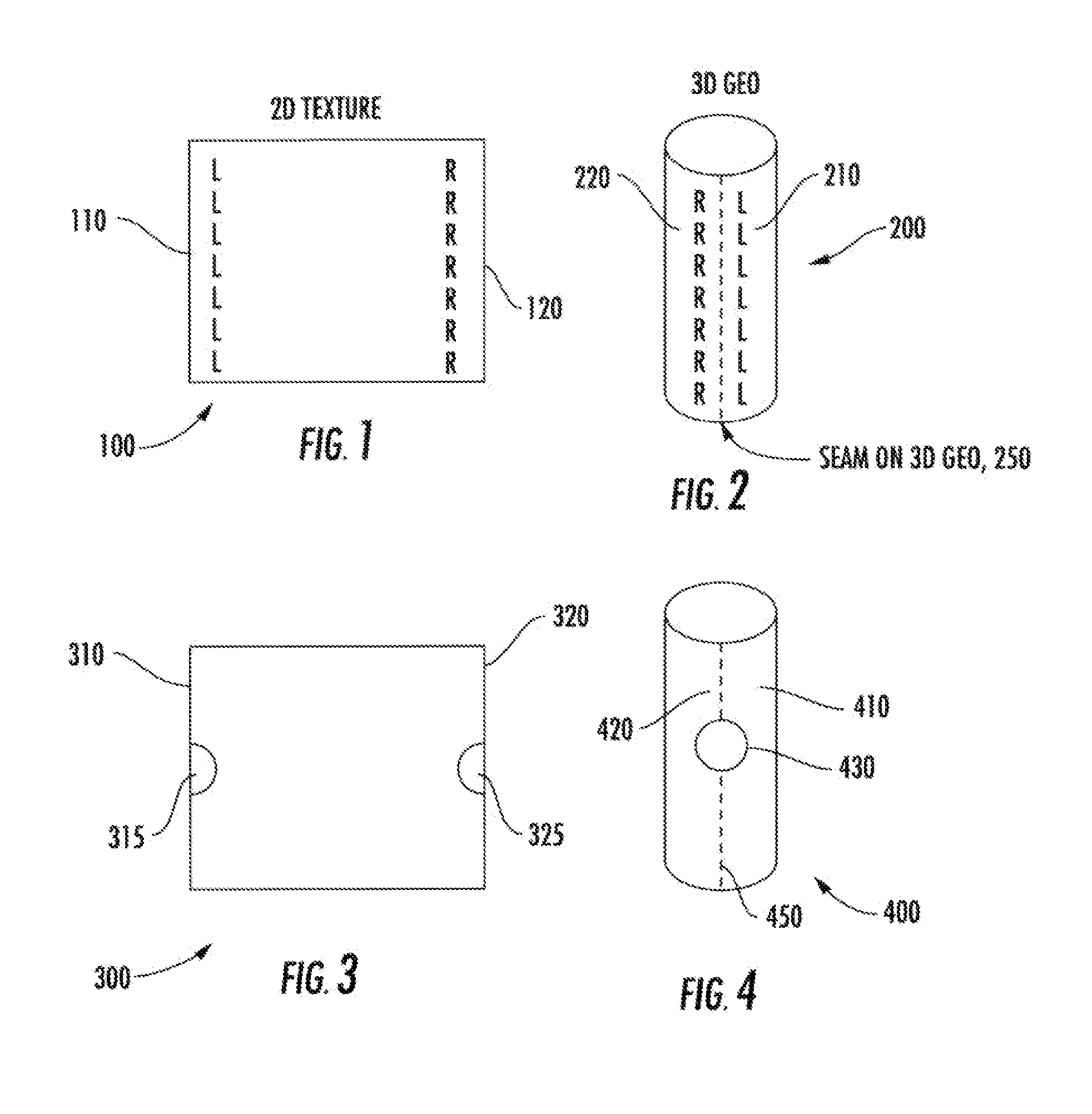
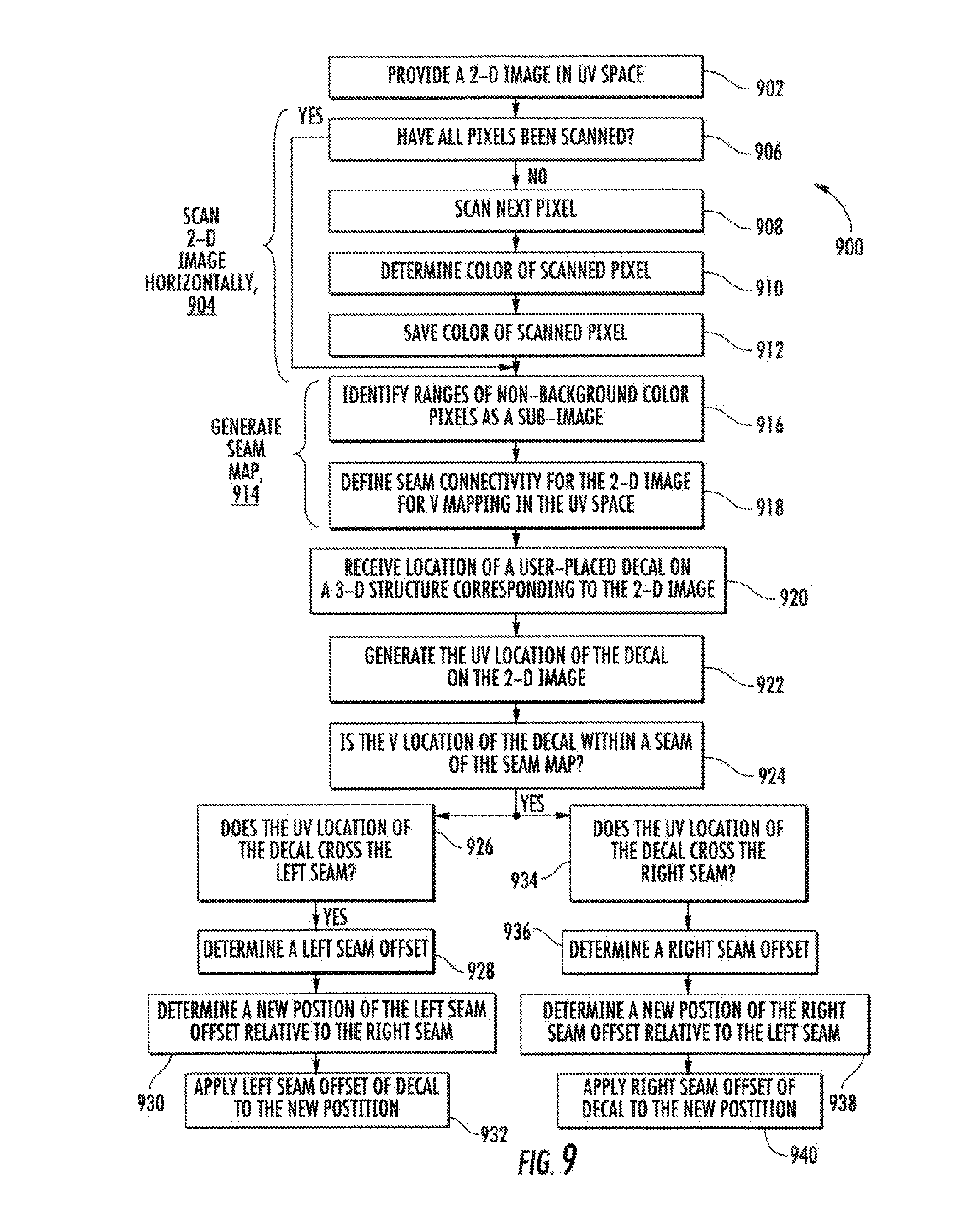
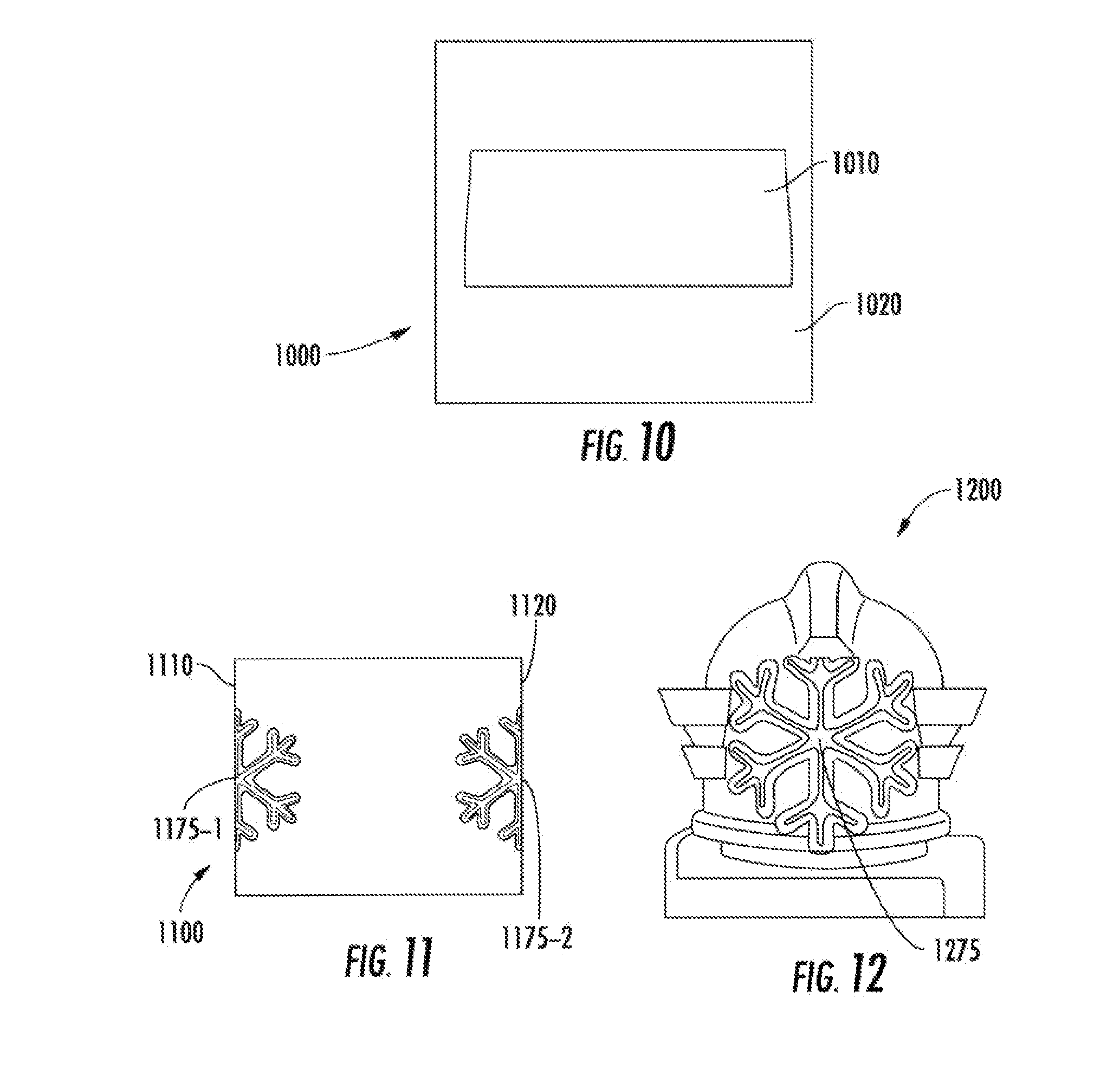
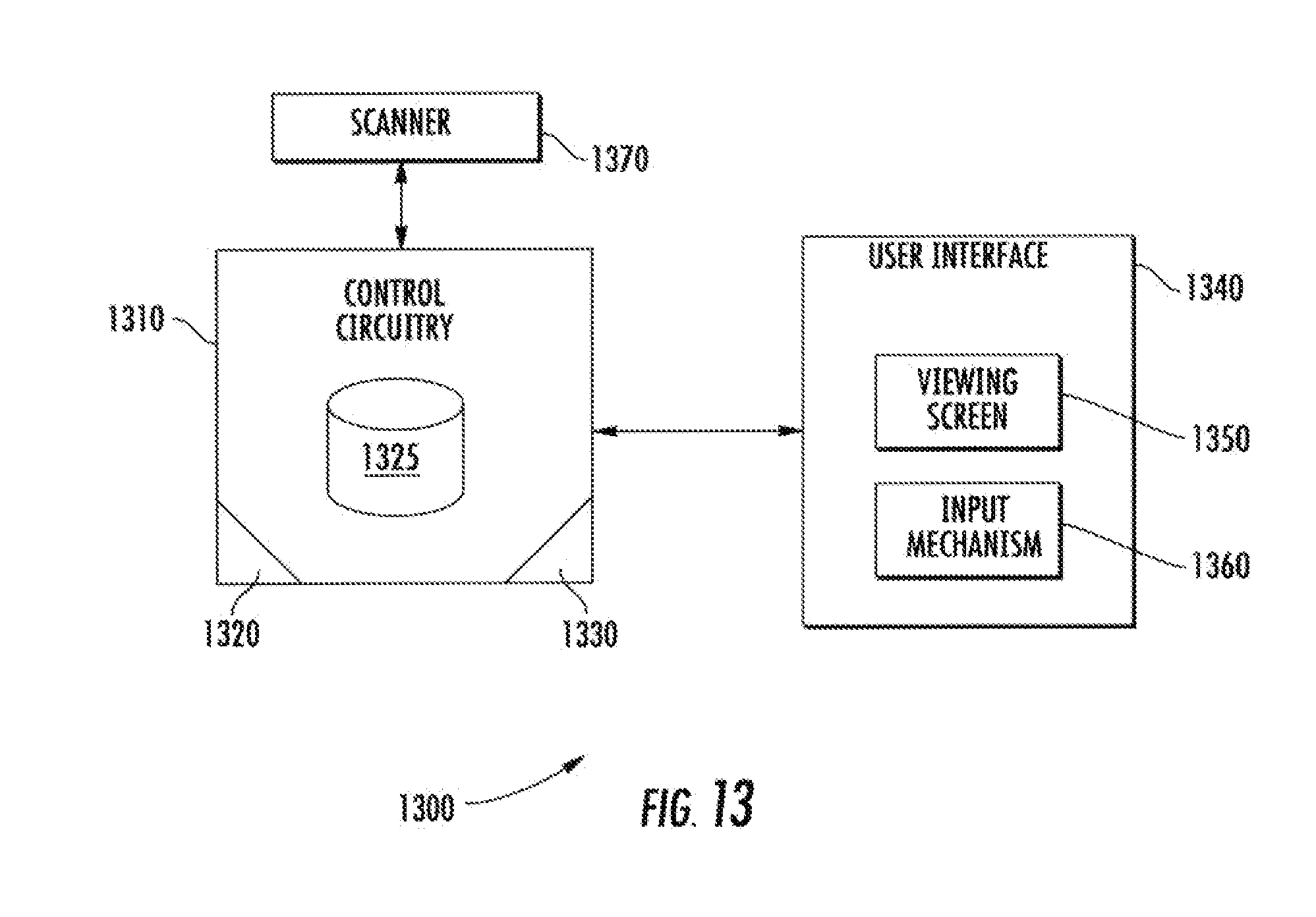
This application claims the benefit of priority under 35 U.S.C. §119(e) of U.S. Provisional Application Ser. No. 61/548,500, filed on Oct. 18, 2011, which application is incorporated by reference herein. The present invention relates generally to computer graphics. More particularly, the present invention relates to systems and methods for resolving seams in computer graphics when a two-dimensional image is applied to a three-dimensional structure. As is known in computer graphics, a two-dimensional image or texture can be applied to a three-dimensional geometry. For example, a two-dimensional photograph can be wrapped around a three-dimensional object. When this is done, seams on the three-dimensional geometry can occur. To create the three-dimensional geometry 200 shown in When it is known in advance that a two-dimensional image will be mapped into a three-dimensional geometry, the two-dimensional image can be mapped or drawn in such a way to hide any resulting seams when the three-dimensional geometry is created. For example, Problems arise when the shape of a three-dimensional geometry is not known in advance because, in these situations, the corresponding two-dimensional image cannot be mapped to hide resulting seams. For example, when a three-dimensional geometry is customized with decals, a corresponding two-dimensional image cannot be mapped in advance to hide seams created by the decals. As seen in Systems and methods have been developed to address the above-identified problems. For example, decal projection has been used. In decal projection, the texture, including the shape and size, of a decal can be projected onto a three-dimensional structure. This is akin to shining a flashlight onto a three-dimensional structure and applying the decal anywhere the light hits. For example, if the flashlight projects a square light, then the resulting decal can be square and be rotated and sized. However, decal projection has presented significant disadvantages. For example, shadows, such as where the three-dimensional structure occludes itself, can occur. Furthermore, bleeding of the decal onto the other side of the structure can occur, and bad stretching, for example, when the structure is parallel to light rays, can occur. In view of the above, improved systems and methods are desired for resolving seams in computer graphics when two-dimensional image is applied to a three-dimensional structure. According to some embodiments, a method is provided. The method can include providing a two-dimensional image in a UV space, identifying, with control circuitry, at least one sub-image on the two-dimensional image, and defining, with control circuitry, a seam connectivity for the two-dimensional image in the UV space. The method can also include receiving, via an input mechanism, a user-selected location for an object on a representation of a three-dimensional structure, generating, with the control circuitry, a UV location for the object on the two-dimensional image, determining if a V location of the object is within at least one seam boundary on the two-dimensional image, and when the V location of the object is within the at least one seam boundary on the two-dimensional image, the control circuitry remapping the object onto the two-dimensional image. A system including executable control software stored on a non-transitory computer readable medium, and at least one programmable processor is also provided. The programmable processor can execute the methods described above, and others in accordance with embodiments of the present invention. While this invention is susceptible of embodiments in many different forms, there are shown in the drawings and will be described herein in detail specific embodiments thereof with the understanding that the present disclosure is to be considered as an exemplification of the principles of the invention. It is not intended to limit the invention to the specific illustrated embodiments. Various embodiments are described that include systems and methods for resolving seams in computer graphics when a two-dimensional image is applied to a three-dimensional structure. In accordance with some embodiments, a seam map of a two-dimensional image can be created that contains connectivity information for mapping the two-dimensional image onto a three-dimensional structure. Then, the seam map can be used so that objects on the two-dimensional image span the three-dimensional object correctly and without seams, even though the two dimensional image does not connect where the object spans. In some embodiments, a seam map can include a two-dimensional image of a geometry mapped in a UV space. It is to be understood that a UV space is space in which a two-dimensional image is mapped into a three-dimensional image or structure. For example, U and V axes can define a two-dimensional UV space, and X, Y, and Z axes can define a three-dimensional space. U and V can be considered akin to X and Y. However, a UV space is only a texture space rather than in a geometrical space. But texture coordinates in a UV space can be used to map a two-dimensional image into a three-dimensional (X, Y, Z) space. The converse is also true. That is, an object in a three-dimensional space can be mapped into a UV space. For example, in some embodiments, UV coordinates can represent a projection of a unit space vector with X, Y, and X coordinates onto the XY plane. That is, U can be defined as follows: Similarly, V can be defined as follows: Referring now to the figures, The executable control software 1330 can implement the exemplary method described herein, for example, as illustrated in A scanner 1370 can be in communication with the control circuitry 1310, and a user interface device 1340 can also be in communication with the control circuitry 1310. A viewing screen 1350 of the user interface device 1340, as would be known by those of skill in the art, can display interactive and viewing windows. In some embodiments, the user interface device 1340 can be a multidimensional graphical user interface, and in some embodiments, the user interface device 1340 can include one or more input mechanisms 1360, for example, a keypad or a mouse, can receive user input. For example, the input mechanism 1360 can receive information from a user related to the location of a user-placed decal on a three-dimensional structure. The viewing screen 1350 can display to a user an image of the structure with the decal. In some embodiments, the control circuitry 1310, programmable processors 1320, and executable control software 1330 can determine a seam map for a two-dimensional image corresponding to the three-dimensional structure and, if necessary, remap the user-placed decal onto the two-dimensional image to account for seams when the decal is subsequently applied, for example, printed onto a three-dimensional structure. As seen in In some embodiments, the two-dimensional image in UV space, for example, the image 1000, can be obtained from an image of a three-dimensional structure. For example, an image of a three-dimensional structure can be mapped into UV space using UV coordinates of triangles on the three-dimensional structure. When mapped into UV space, an island of interest in the UV space can be determined. For example, an island can be a non-background color geometry with connecting coordinates in UV space. That is, all geometry in an island is connected in UV space and is contained entirely within a border of a UV seam. An island of interest in the UV space can be the island with a UV seam to be resolved in accordance with the systems and methods described herein. As seen in After the two dimensional image in the UV space is provided as in 902, the method 900 can scan through the image horizontally from a first side of the image to a second side of the image as in 904. For example, the scanner 1370 in communication with the control circuitry 1310 can scan the image. In some embodiments, the method can scan the image pixel by pixel as in 908. While scanning the image, the method can determine the color of each pixel as in 910 and save, in a memory, for example, the color of each pixel as in 912. For example, the control circuitry 1310, programmable processors 1320, and executable control software 1330 can determine the color of each pixel and save the color of each pixel in the memory device 1325. For example, if the method determines that a particular pixel is a color that is different than the color of the background portion of the image, then the location of the non-background color pixel can be saved, for example, in the memory device 1325. When the method finds a series of non-background color pixels, the method can determine that it is scanning a sub-image of the image. When the method is scanning a sub-image of the image, the method can continue scanning the image. When the method determines that a particular pixel is a background color or that the right edge of the image has been reached and there are no more pixels to scan, the location of the background color pixel or the last non-background color pixel can be saved, for example, in the memory device 1325 After horizontal scanning of the image is complete as in 904, the range of pixels that are non-background color can be identified as a sub-image of the image as in 916. The range of pixels constituting a sub-image of the image can define the seam connectivity for image in the V mapping of the UV space as in 918. That is, for any given V value identified as a seam, the corresponding U value can be mapped to account for a seam of the sub-image in a three-dimensional structure. The image, with the identified sub-image and seam connectivity, can constitute a seam map in accordance with some embodiments. Accordingly, in some embodiments, the control circuitry 1310, programmable processors, and executable control software 1330 can generate the seam map. In some embodiments, defining the seam connectivity for an image can include identifying edges, that is, seams, of a sub-image. For example, defining the seam connectivity can include identifying areas of a sub-image in which seams will occur when the sub-image is applied to a three-dimensional structure. In some embodiments, when a seam map image as in 914 is created, seams, that is, edges of a sub-image, can be indicated with a different colored pixel, for example, a red or blue colored. In these embodiments, subsequent processing can be eased because the method can easily and readily identify the location of seams. According to some embodiments, a user can place or select a location for placing a decal or other object on a three-dimensional structure as in 920. For example, the user can enter input via the input mechanisms 1360 of the user interface device 1340 to place or select a location for placing the decal. Then, the method 900 can generate a UV location of the decal on the two-dimensional image as in 922. For example, the control circuitry 1310, programmable processors 1320, and executable control software 1330 can generate the UV location of the decal. In some embodiments, if a user places a decal with a computer mouse, a ray collision test can be conducted between the mouse location and the three-dimensional geometry to generate a UV location of the decal on the corresponding and underlying two-dimensional image. The V location of the UV location of the decal can be compared with the seam map generated to determine if the UV location is within a seam on the seam map as in 924. If the UV location of the decal is within the bounds of a seam, additional steps can occur. For example, if the UV location of the decal is within the bounds of the seam map, the method can determine if the UV location of the decal crosses a left seam boundary as in 926. If the UV location of the decal does cross the left seam boundary, the method can account for a scaled and rotated decal by determining the left seam offset as in 928, computing the new position of the left seam offset relative to the right seam as in 930, and applying the left seam offset of the decal at the new position as in 932. In some embodiments, the control circuitry 1310, programmable processors 1320, and executable control software 1330 can determine if the UV location of the decal is within a seam on the seam map and crosses a left seam boundary. If so, the control circuitry 1310, programmable processors 1320, and executable control software 1330 can determine the left seam offset, compute the new position of the left seam offset, and apply the left seam offset at the new position. In some embodiments, the left seam offset, delta L, can be equal to the original decal position minus the left seam location. Further, the new position of the left seam offset relative to the right seam can be equal to the right seam location plus the left seam offset, delta L. If the original UV location of the decal is within the bounds of the seam map, the method can also determine if the original UV location of the decal crosses a right seam boundary as in 934. If the UV location of the decal does cross the right seam boundary, the method can account for a scaled and rotated decal by computing the right seam offset as in 936, computing the new position of the right seam offset relative to the left seam as in 938, and applying the right seam offset of the decal at the new position as in 940. In some embodiments, the control circuitry 1310, programmable processors 1320, and executable control software 1330 can also determine if the UV location of the decal crosses a right seam boundary and, if so, compute the right seam offset, compute the new position of the right seam offset, and apply the right seam offset at the new position. In some embodiments, the right seam offset, delta R, can be equal to the original decal position minus the right seam location. Further, the new position of the right seam offset relative to the left seam can be equal to the left seam location plus the right seam offset, delta R. Applying any left and right seam offsets of a decal to new positions on the two-dimensional image as in 932 and 940 can constitute remapping the decal onto the image. In some embodiments, remapping a decal onto a two-dimensional image can account for seams when the image and decal are applied to a three-dimensional structure. The image 1100 shown in Further embodiments include masking of certain portions of a two-dimensional image in a UV space. In some embodiments in which multiple sub-images are included in the two-dimensional image in a UV space, such as the image of Although a few embodiments have been described in detail above, other modifications are possible. For example, the logic flows depicted in the figures do not require the particular order shown, or sequential order, to achieve desirable results. Other steps may be provided, or steps may be eliminated, from the described flows, and other components may be added to, or removed from, the described systems. Other embodiments may be within the scope of the following claims. From the foregoing, it will be observed that numerous variations and modifications may be effected without departing from the spirit and scope of the invention. It is to be understood that no limitation with respect to the specific system or method illustrated herein is intended or should be inferred. It is, of course, intended to cover by the appended claims all such modifications as fall within the spirit and scope of the claims. Systems and methods are provided for resolving seams in computer graphics when a two-dimensional image is applied to a three-dimensional structure. The method can include providing a two-dimensional image in a UV space, identifying at least one sub-image on the two-dimensional image, defining a seam connectivity for the two-dimensional image in the UV space, and remapping the location of an object on the two-dimensional image when the location of the object is within at least one seam boundary of the seam map. 1. A method comprising:
providing a two-dimensional image in a UV space; identifying, with control circuitry, at least one sub-image on the two-dimensional image; and defining, with the control circuitry, a seam connectivity for the two-dimensional image in the UV space. 2. The method of 3. The method of 4. The method of 5. The method of 6. The method of 7. The method of 8. The method of 9. The method of receiving, via an input mechanism, a user-selected location for an object on a representation of a three-dimensional structure; generating, with the control circuitry, a UV location for the object on the two-dimensional image; determining if a V location of the object is within at least one seam boundary on the two-dimensional image; and when the V location of the object is within the at least one seam boundary on the two-dimensional image, the control circuitry remapping the object onto the two-dimensional image. 10. The method of 11. The method of 12. The method of 13. The method of 14. The method of 15. A system comprising:
executable control software stored on a non-transitory computer readable medium; and at least one programmable processor for:
providing a two-dimensional image in a UV space; identifying at least one sub-image on the two-dimensional image; and
defining a seam connectivity for the two-dimensional image for V mapping the in the UV space. 16. The system of 17. The system of 18. The system of 19. The system of 20. The system of 21. The system of 22. The system of 23. The system of 24. The system of 25. The system of 26. The system of 27. The system of 29. The system of CLAIM OF PRIORITY
FIELD
BACKGROUND
SUMMARY
BRIEF DESCRIPTION OF THE DRAWINGS
DESCRIPTION OF THE PREFERRED EMBODIMENTS