Pipe Compression Clamp
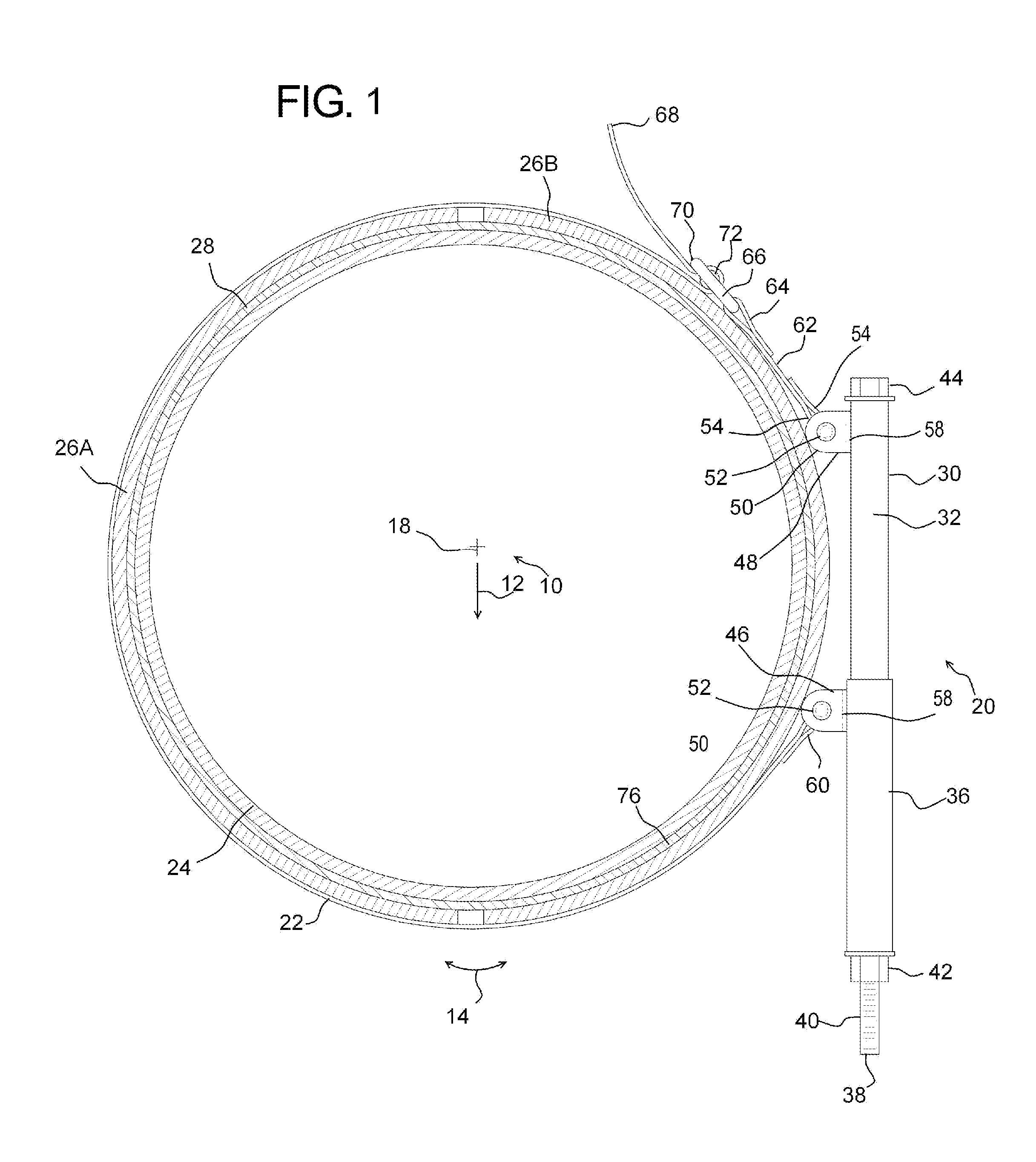
This application claims priority benefit of U.S. provisional application, Ser. No. 61/590,212, filed Jan. 24, 2012, to Carl M. Brooks and Larry Mehlenbacher. The provisional application incorporated herein by reference. This application applies to the field of temporary and re-usable compression pipe clamps to be used in pipe repair processes. Disclosed herein is a high compression pipe clamp which in one embodiment has a hollow rigid inner housing and a hollow rigid outer housing. The hollow rigid inner housing may have a first end, an outer diameter, and a first strap bracket. The hollow rigid outer housing may have a first end, an inner diameter and a second strap bracket wherein the inner diameter of the outer housing is larger than the outer diameter of the inner housing to fit thereover. A threaded rod is also disclosed, the threaded rod passing through the inner housing and outer housing and a threaded nut engaging the threads on the threaded rod. A strap is also disclosed, the strap having a first end attached to the first strap bracket and a second end attached to the second strap bracket. The strap in operation wraps about the pipe to compress the pipe radially. While strap-type pipe wrenches are well known in the art, the disclosed pipe clamp is made to achieve very high compression of the pipe and external attachments thereto. The pipe clamp is arranged such that rotation of the threaded rod in a first rotational direction relative to the threaded nut repositions the first strap bracket towards the second strap bracket to reduce the effective inner diameter of the strap and housing combination around a section of pipe. In one form, the hollow rigid inner housing and the hollow rigid outer housing are rectangular in cross section. They may also be rectangular or square in cross section. Square being a special rectangle with even or equal sides. The hollow rigid inner housing and the hollow rigid outer housing may also be curvilinear, triangular, or substantially any other shape in cross section. In one form, the pipe clamp as recited above is arranged wherein the strap is positionably coupled to one or both of the first strap bracket or second strap bracket. This allows for an initial adjustment for different diameter pipes, and improves convenience of application of the clamp in position. The pipe clamp as recited in claim 1 wherein the strap comprises a first portion and a separate second portion adjustably coupled to the first portion. The pipe clamp as recited above may be used in a method for repairing or reinforcing a portion of pipe comprising several steps. These steps may include: providing a compression pipe clamp as recited above, disposing a volume of adhesive to a portion of the outer surface of the pipe; positioning a rigid sleeve portion over the adhesive; and/or positioning the strap of the pipe clamp around the pipe and sleeve. The threaded rod may then be rotated in a first rotational direction relative to the threaded nut so as to reposition the first strap second strap bracket towards the second strap bracket to reduce the effective inner diameter of the strap and housing combination around a section of pipe. In this way, the pipe clamp compresses the sleeve onto the pipe, providing an exceptional seal during final repair of the pipe. This disclosure describes a compression pipe clamp 20 which may be used in combination with several of the repair methods claimed in U.S. patent application Ser. No. 12/368,106 which is now U.S. Pat. No. 7,938,146, incorporated herein by reference. The disclosed pipe clamp provides for a high compression between a repair sleeve and a pipe to be repaired or reinforced. Such applications include the repairs shown in The reference patent has a great deal of detail of several variants of a repair process. One repair process generally comprises the steps of cleaning and potentially upgrading the outer surface of the pipe in the location to be repaired, and removing contaminants from the surface. Methyl ethyl ketone (MEK) or other cleansing agents may be utilized to remove all surface contaminants. A fine layer of adhesive may then be applied to the outer surface of the pipe or alternatively to the inner surface of a repair sleeve or plurality of repair sleeves. It may be desired to then disperse (distribute evenly) this layer of adhesive 28 at which point the repair sleeve is placed over top of the pipe to cover the section to be repaired or reinforced. The compression clamps disclosed herein may then be placed around the entire assembly and compressed there about to further spread the adhesive layer 28 and firmly secure the repair sleeve 26 in place. At this point, the edges of the repair sleeve may be welded to the pipe, the entire apparatus may be wrapped with a rigid securing component, or potentially the compression clamps 20 may remain in place. Before beginning, a detailed description an axes systems 10 is shown in Looking to The compression clamp 20 as shown comprises an inner housing 30, with an outer surface 32 positioned within an inner surface 34 of the outer housing 36. The inner surface 34 of the inner housing 30 is more easily seen in The inner housing 30 of the example shown in As shown, a first strap bracket 48 is welded, bolted, or otherwise attached to the inner housing 30. The first strap bracket 48 in one form has a plurality of extensions 50 more easily seen in To allow for adjustability of the strap 22, a length adjustment system may be utilized. While several different forms are conceived, one particular embodiment is shown in Once the appropriate number of compression clamps 20 are in place. about the repair structure (sleeve 26), either the bolt head 44 and/or nut 42 are rotated to draw the bracket 48 toward the bracket 46 and thus compress the strap 22 about the repair structure. U.S. Pat. No. 7,938,146 discloses additional steps of a repair process which may be used in conjunction with the disclosed clamp. The process including additional steps of disposing at least one layer of fibrous material upon the layer of adhesive; wherein the layer of fibrous material comprises fibers such as carbon fiber, fiberglass and similar materials. As can be seen in A following step of the repair process may be to dispose at least one layer of a second fibrous material upon the layer of second adhesive. This layer of second fibrous material may comprise fibers substantially in alignment with the circumference of the pipe; and a portion of the second adhesive may be disposed between adjacent fibers of the second fibrous material when cured. The graphs below and What was recorded?
Assessment of Measurements
While the present invention is illustrated by description of several embodiments and while the illustrative embodiments are described in detail, it is not the intention of the applicants to restrict or in any way limit the scope of the appended claims to such detail. Additional advantages and modifications within the scope of the appended claims will readily appear to those sufficed in the art. The invention in its broader aspects is therefore not limited to the specific details, representative apparatus and methods, and illustrative examples shown and described. Accordingly, departures may be made from such details without departing from the spirit or scope of applicants' general concept. Disclosed herein is a high compression pipe clamp which in one embodiment has a hollow rigid inner housing and a hollow rigid outer housing. The hollow rigid inner housing may have a first end, an outer diameter, and a first strap bracket. The hollow rigid outer housing may have a first end, and inner diameter and a second strap bracket wherein the inner diameter of the outer housing is larger than the outer diameter of the inner housing to fit thereover. A threaded rod is also disclosed, the threaded rod passing through the inner housing and outer housing and a threaded nut engaging the threads on the threaded rod. 1. A high compression pipe clamp comprising:
a. a hollow rigid inner housing having a first end, an outer diameter, and a first strap bracket; b. a hollow rigid outer housing having a first end, and inner diameter and a second strap bracket wherein the inner diameter of the outer housing is larger than the outer diameter of the inner housing to fit thereover; c. a threaded rod passing through the inner housing and outer housing; d. a threaded nut engaging the threads on the threaded rod; e. a strap having a first end attached to the first strap bracket and a second end attached to the second strap bracket; and f. wherein rotation of the threaded rod in a first rotational direction relative to the threaded nut repositions the first strap second strap bracket towards the second strap bracket to reduce the effective inner diameter of the strap and housing combination around a section of pipe. 2. The pipe clamp as recited in 3. The pipe clamp as recited in 4. The pipe clamp as recited in 5. The pipe clamp as recited in 6. A method for repairing or reinforcing a portion of pipe comprising the steps of:
a. providing a compression pipe clamp comprising;
i. a hollow rigid inner housing having a first end, an outer diameter, and a first strap bracket; ii. a hollow rigid outer housing having a first end, and inner diameter and a second strap bracket wherein the inner diameter of the outer housing is larger than the outer diameter of the inner housing to fit thereover; iii. a threaded rod passing through the inner housing and outer housing; iv. a threaded nut engaging the threads on the threaded rod; v. wherein rotation of the threaded rod in a first rotational direction relative to the threaded nut repositions the first strap second strap bracket towards the second strap bracket to reduce the effective inner diameter of the strap and housing combination around a section of pipe; vi. a strap having a first end attached to the first strap bracket and a second end attached to the second strap bracket; b. disposing a volume of a first adhesive to a portion of the outer surface of the pipe; c. positioning a rigid sleeve over the first adhesive; d. positioning the strap of the pipe clamp around the rigid sleeve; e. rotating of the threaded rod in a first rotational direction relative to the threaded nut repositions the first strap second strap bracket towards the second strap bracket to reduce the effective inner diameter of the strap and housing combination around a section of pipe; and f. releasing and removing the compression pipe clamp. 7. The method as recited in a. disposing at least one layer of fibrous material upon the layer of adhesive; b. wherein the layer of fibrous material comprises fibers; c. disposing at least one layer of a second adhesive upon the fibrous material; d. wherein the second adhesive is comprised of a compound which cures to a substantially rigid state; e. disposing at least one layer of a second fibrous material upon the layer of second adhesive; f. wherein the layer of second fibrous material comprises fibers substantially in alignment with the circumference of the pipe; and g. wherein a portion of the second adhesive is disposed between adjacent fibers of the second fibrous material when cured.RELATED APPLICATIONS
BACKGROUND OF THE DISCLOSURE
Field of the Disclosure
SUMMARY OF THE DISCLOSURE
BRIEF DESCRIPTION OF THE DRAWINGS
DESCRIPTION OF THE PREFERRED EMBODIMENTS
S1 1 −1114 −33,420 −980 −869 2 −1462 −43,860 −1,287 (psi) 3 −385 −11,550 −339 S2 1 −749 −22,470 −659 −798 2 −1230 −36,900 −1,082 (psi) 3 −741 −22,230 −652