TEMPORARY SUPPORT
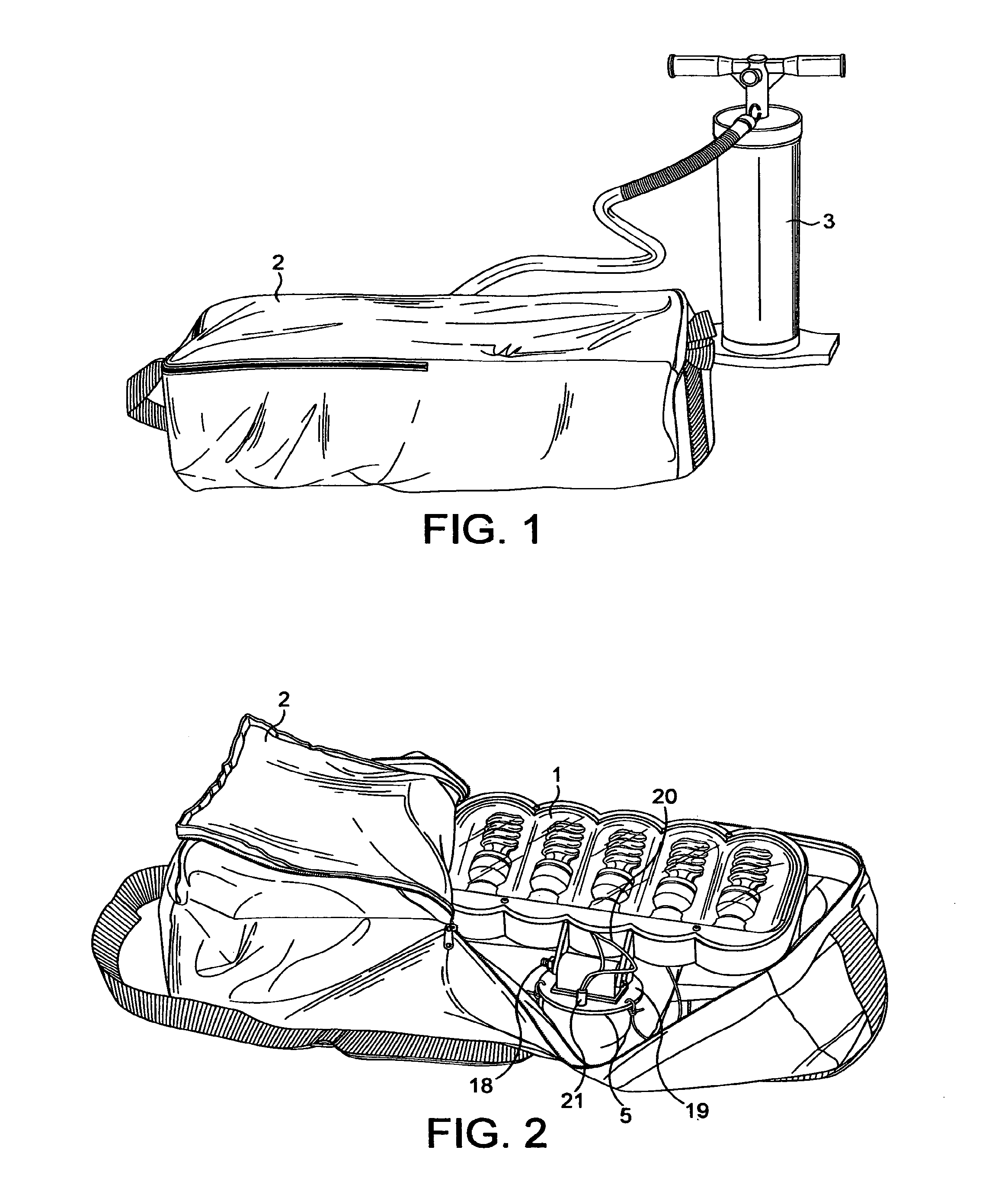
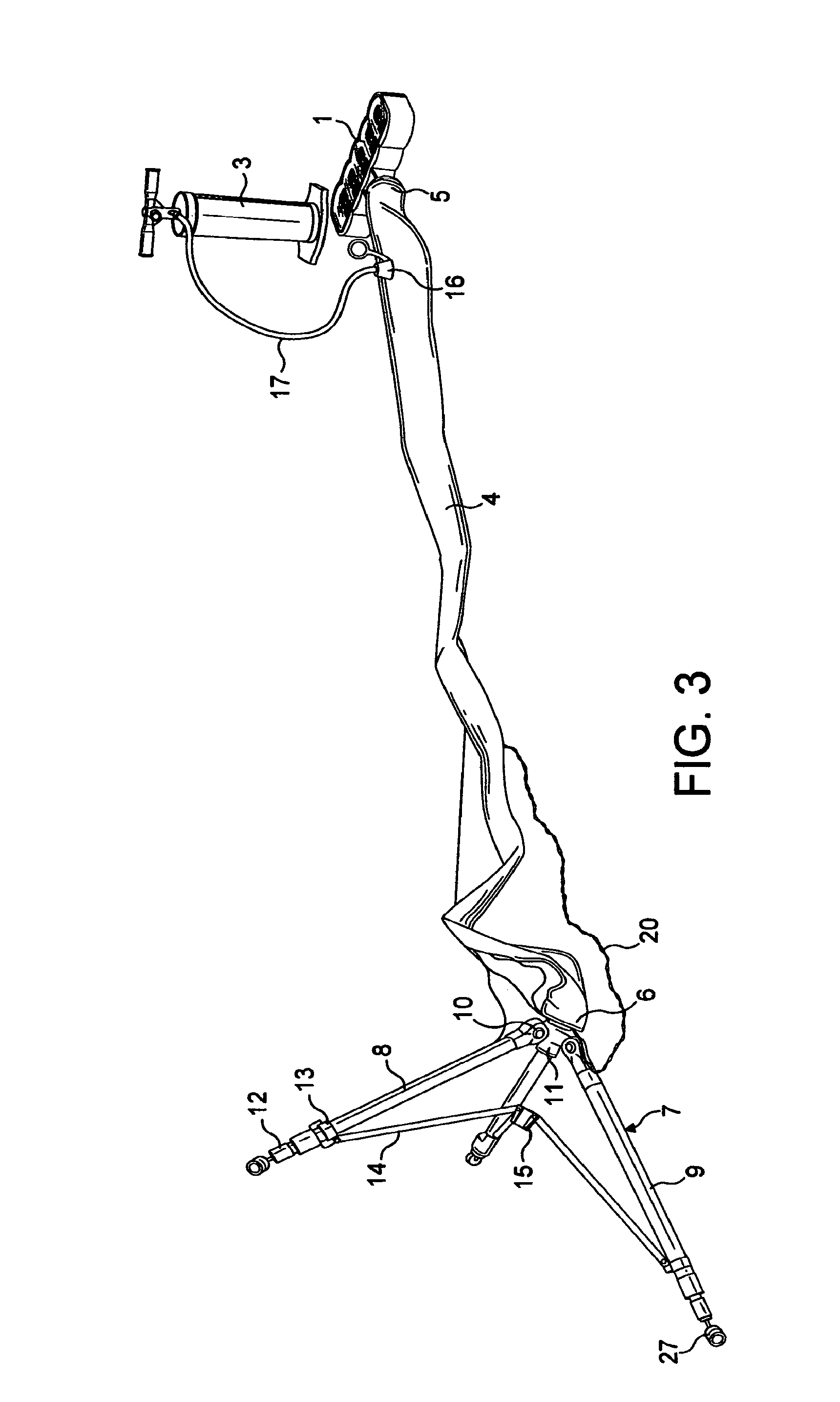
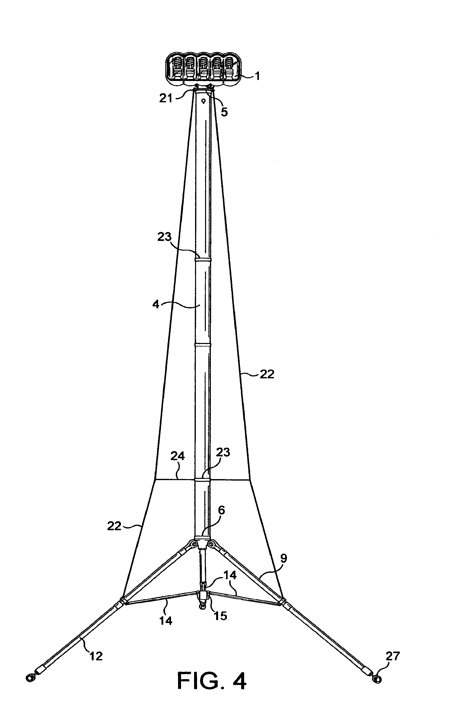
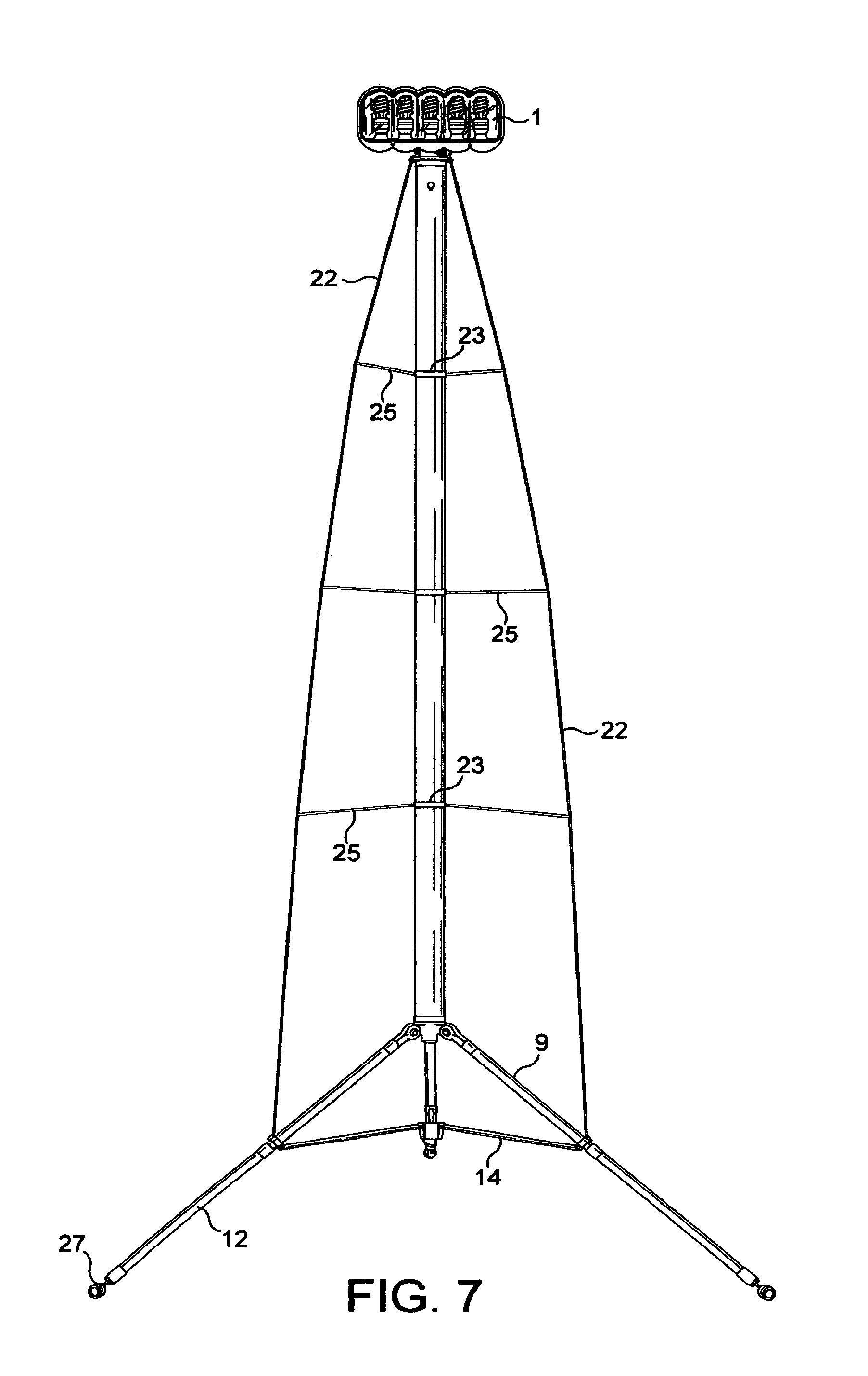
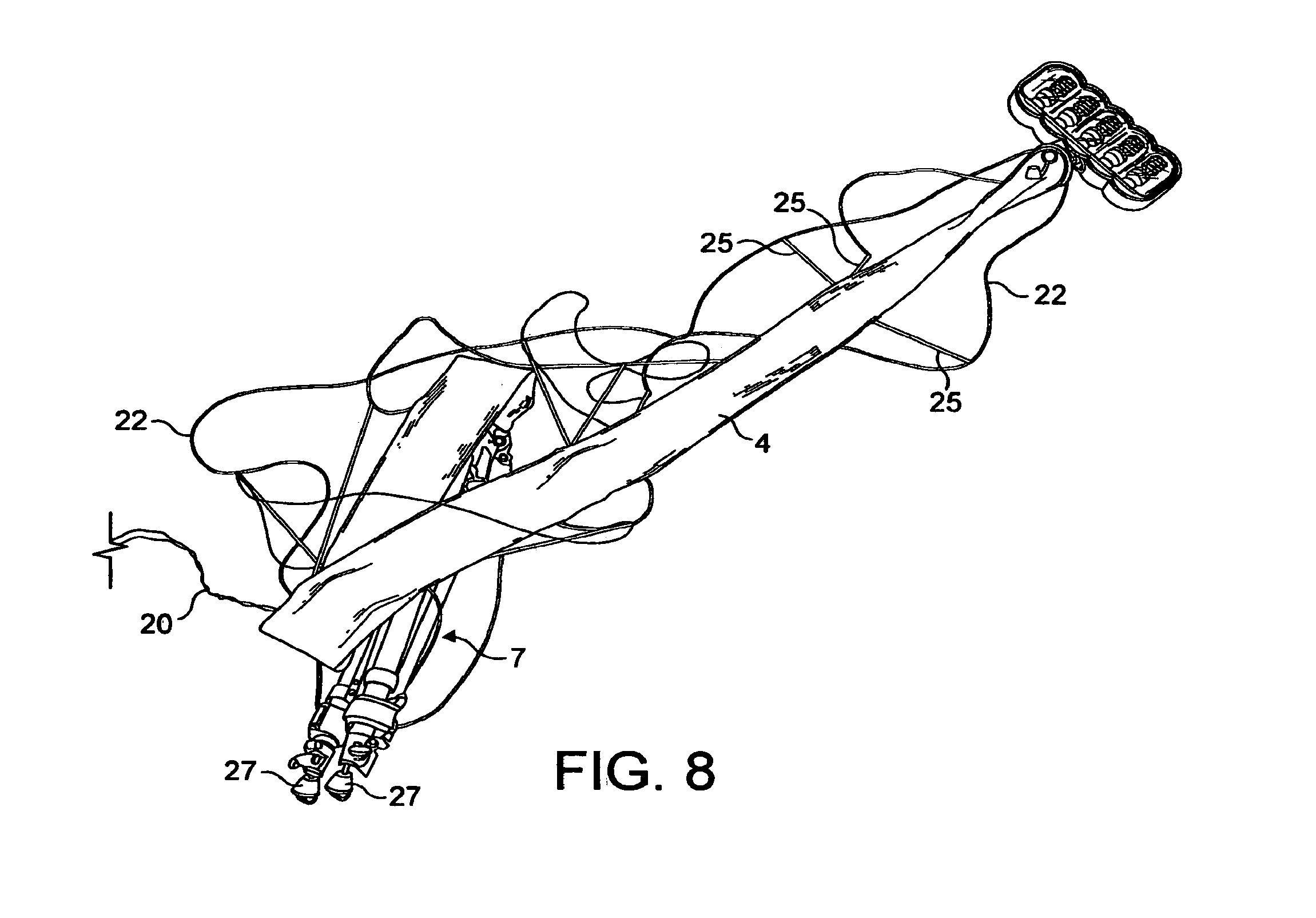
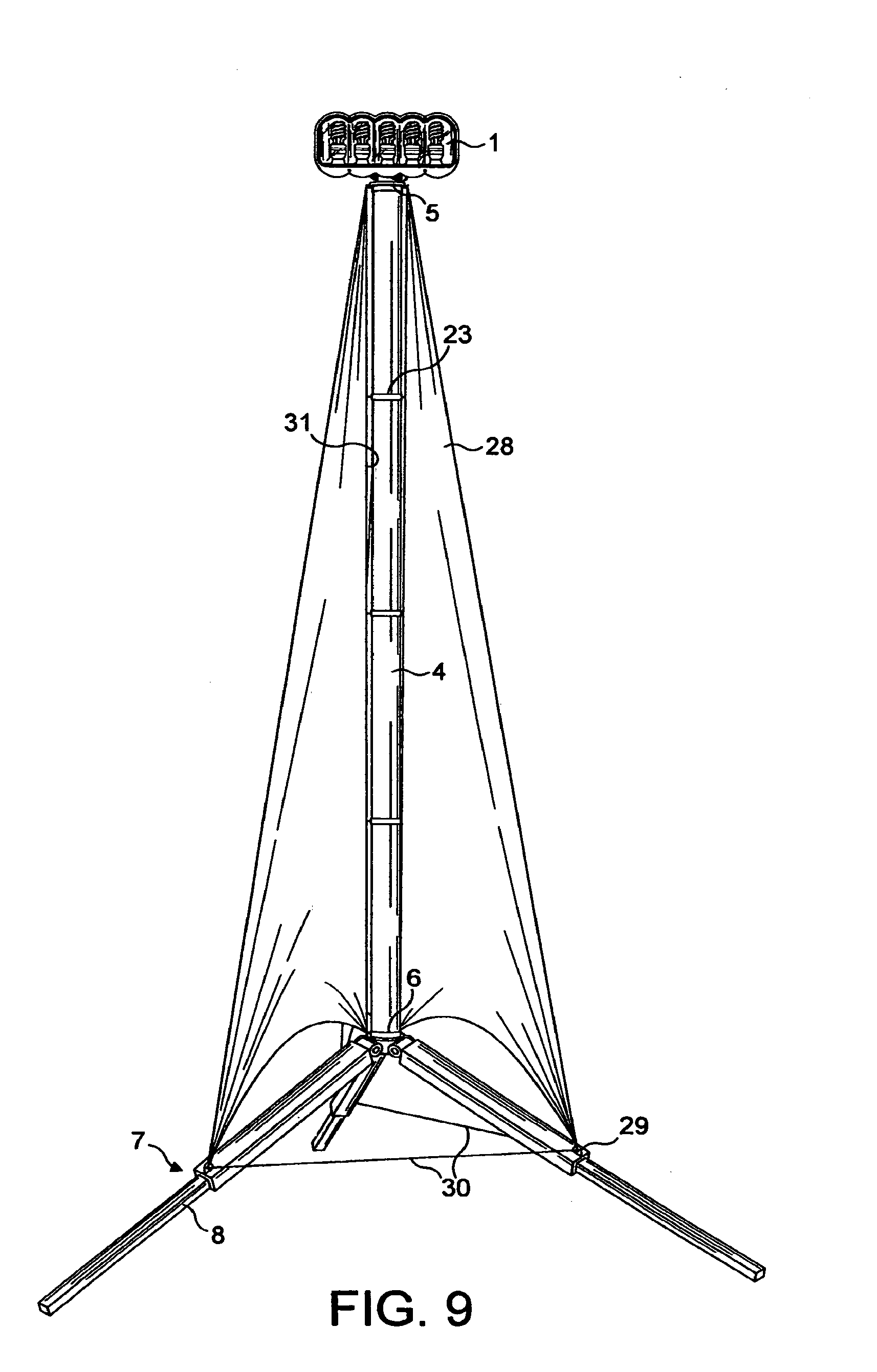
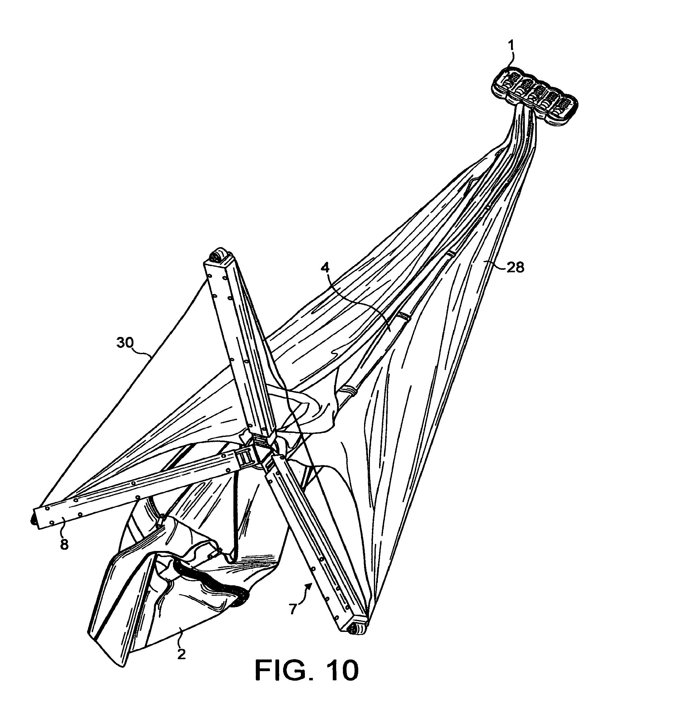
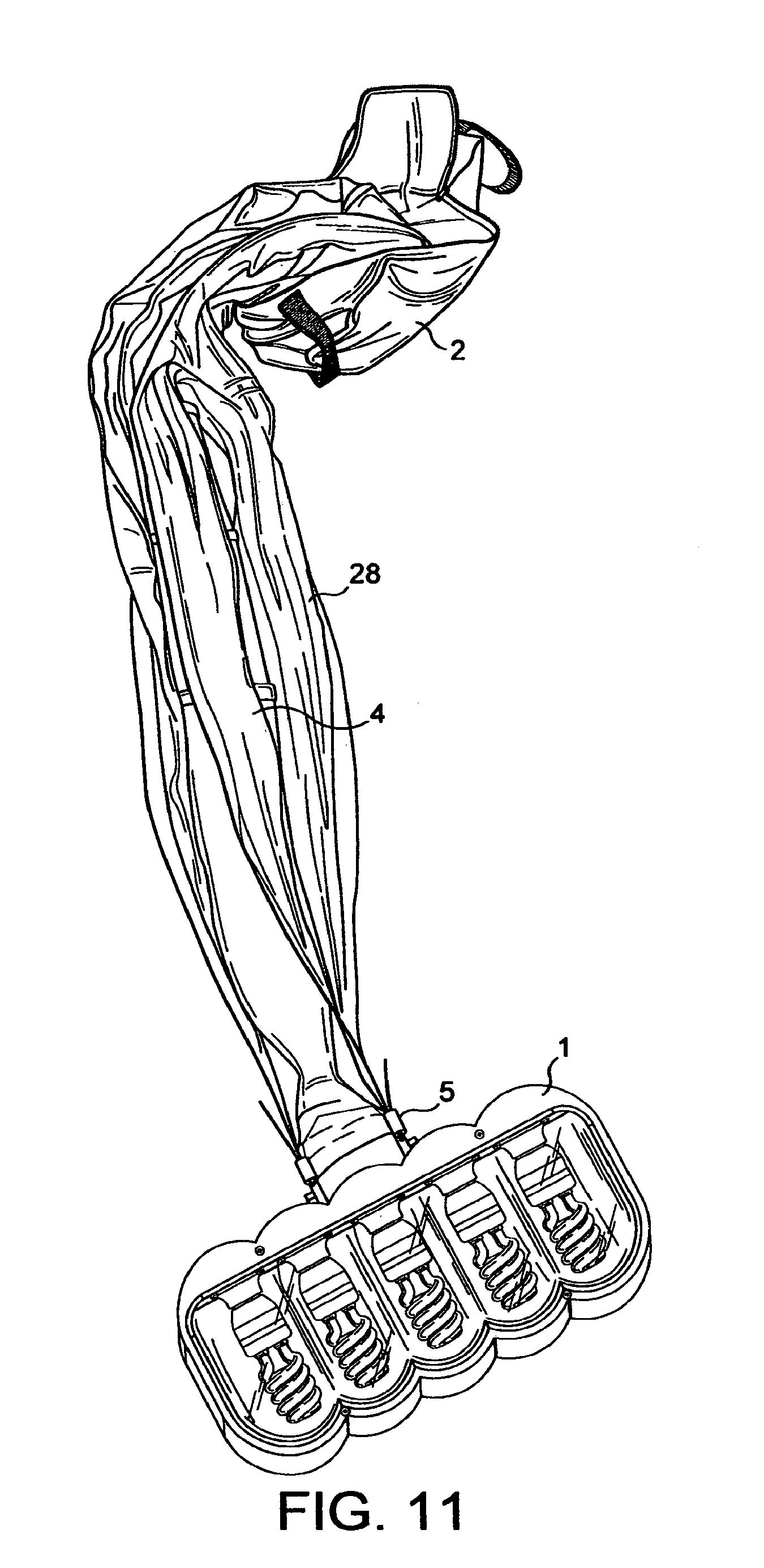
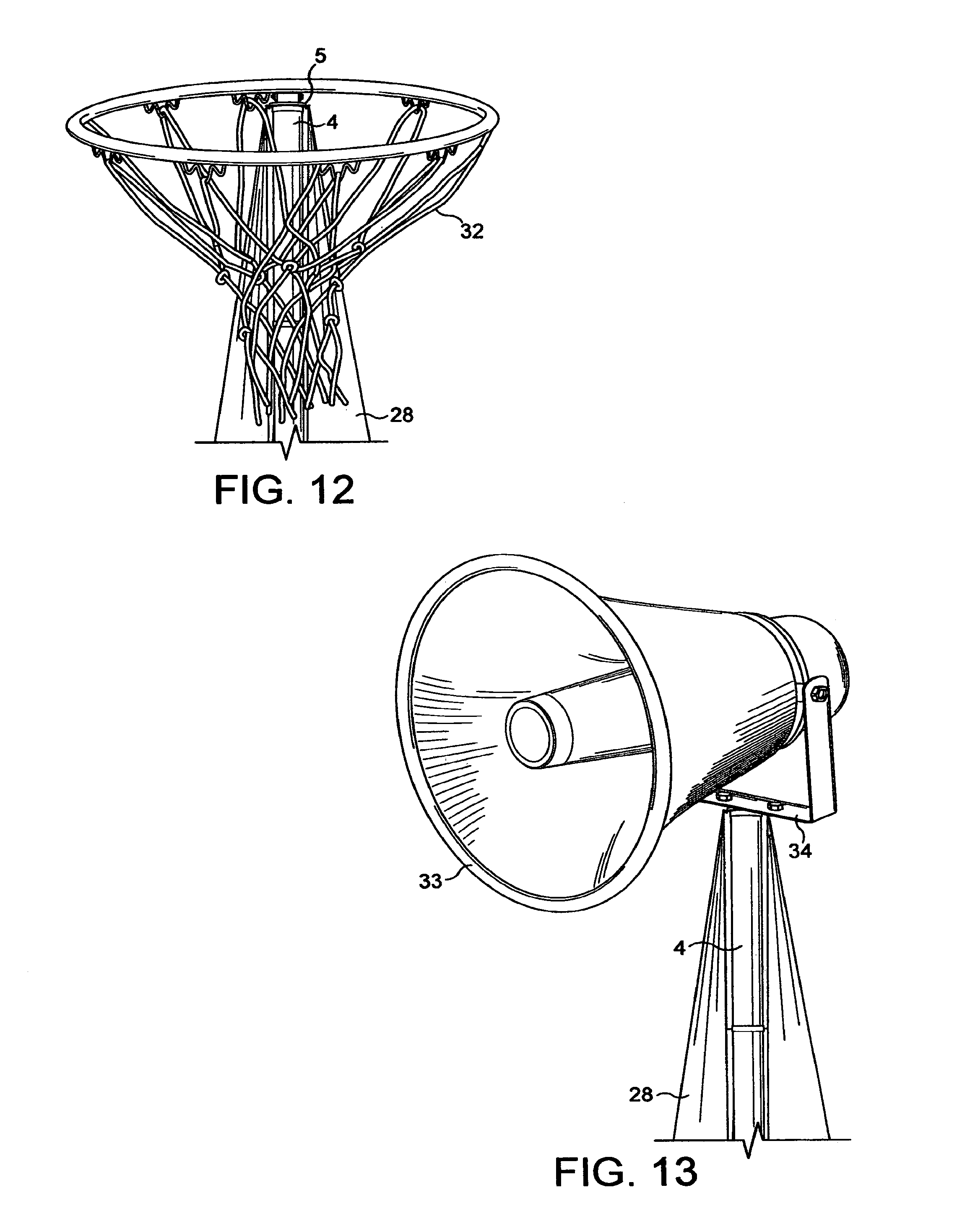
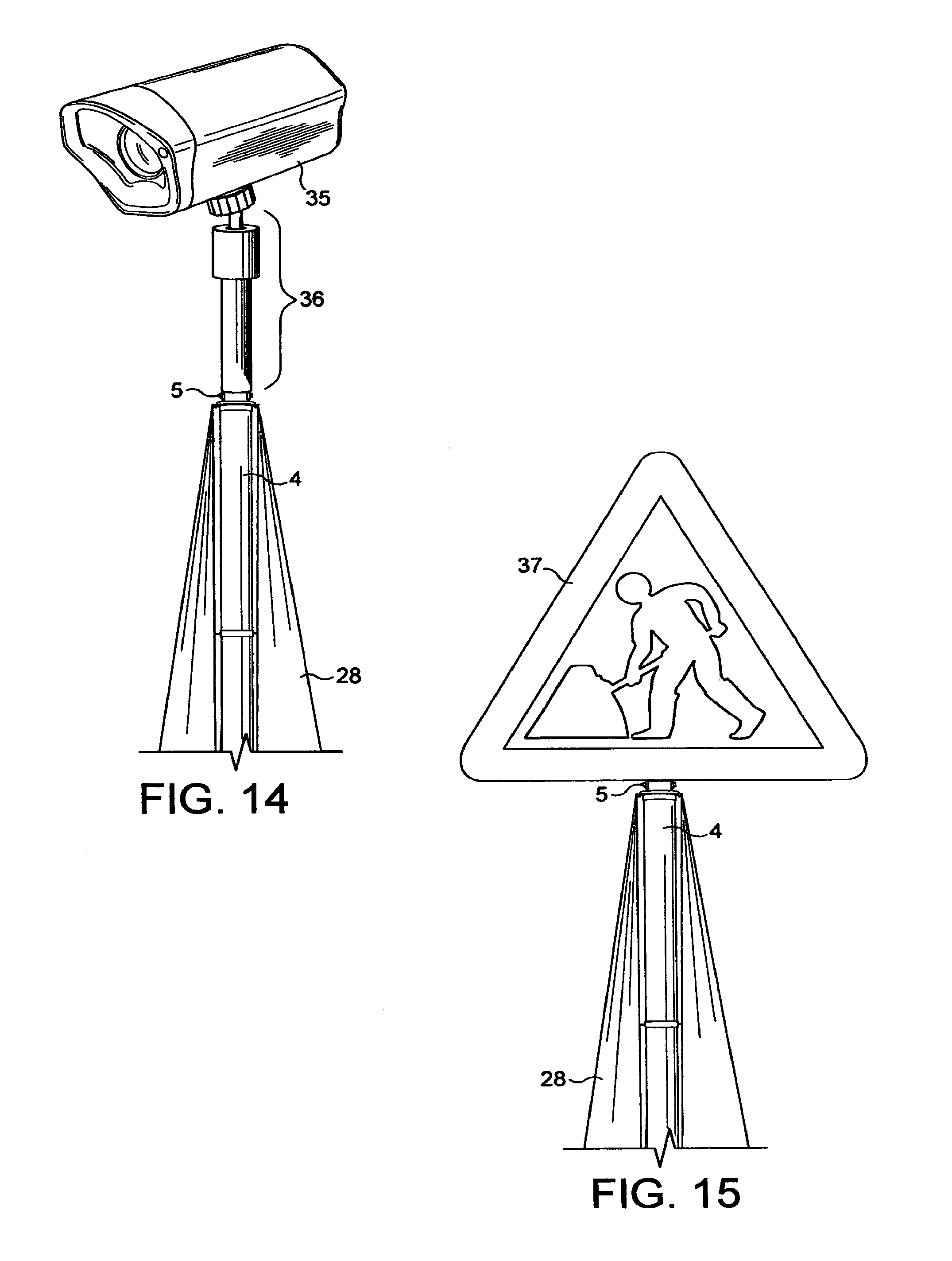
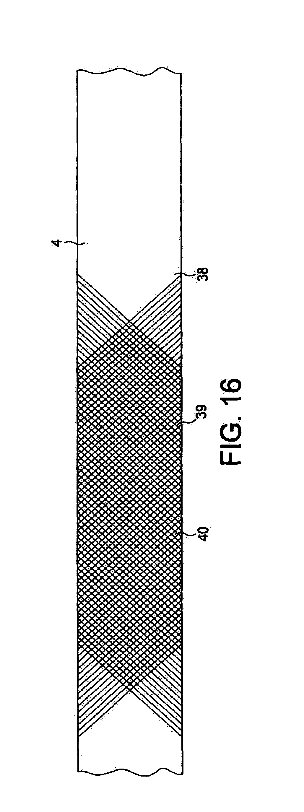
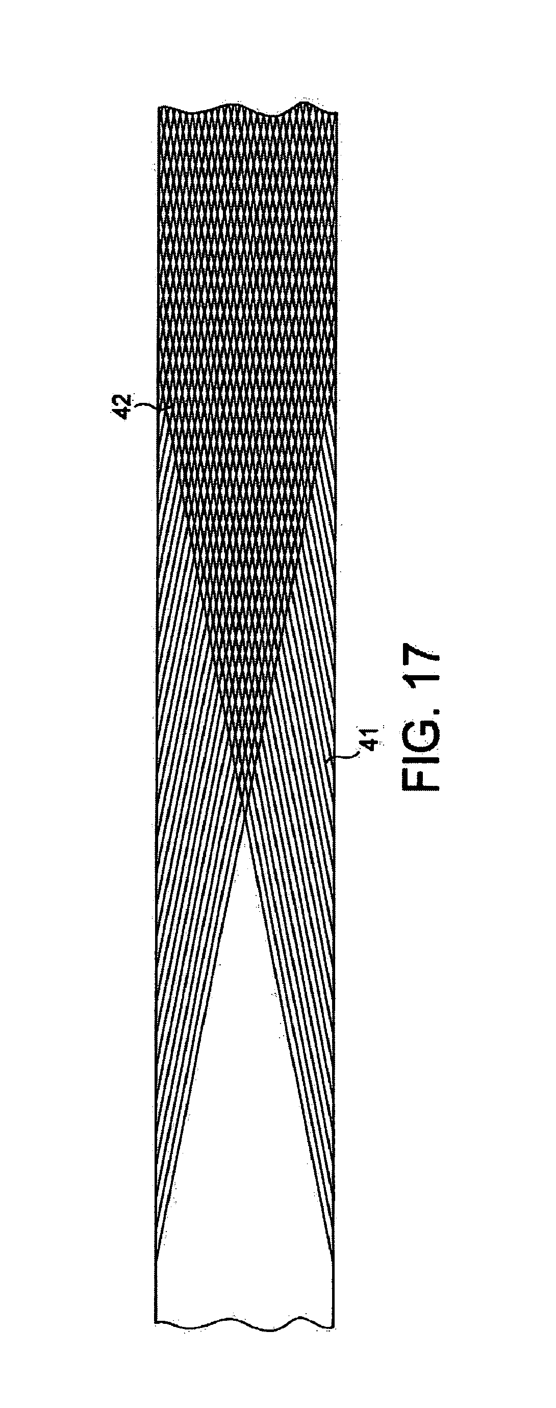
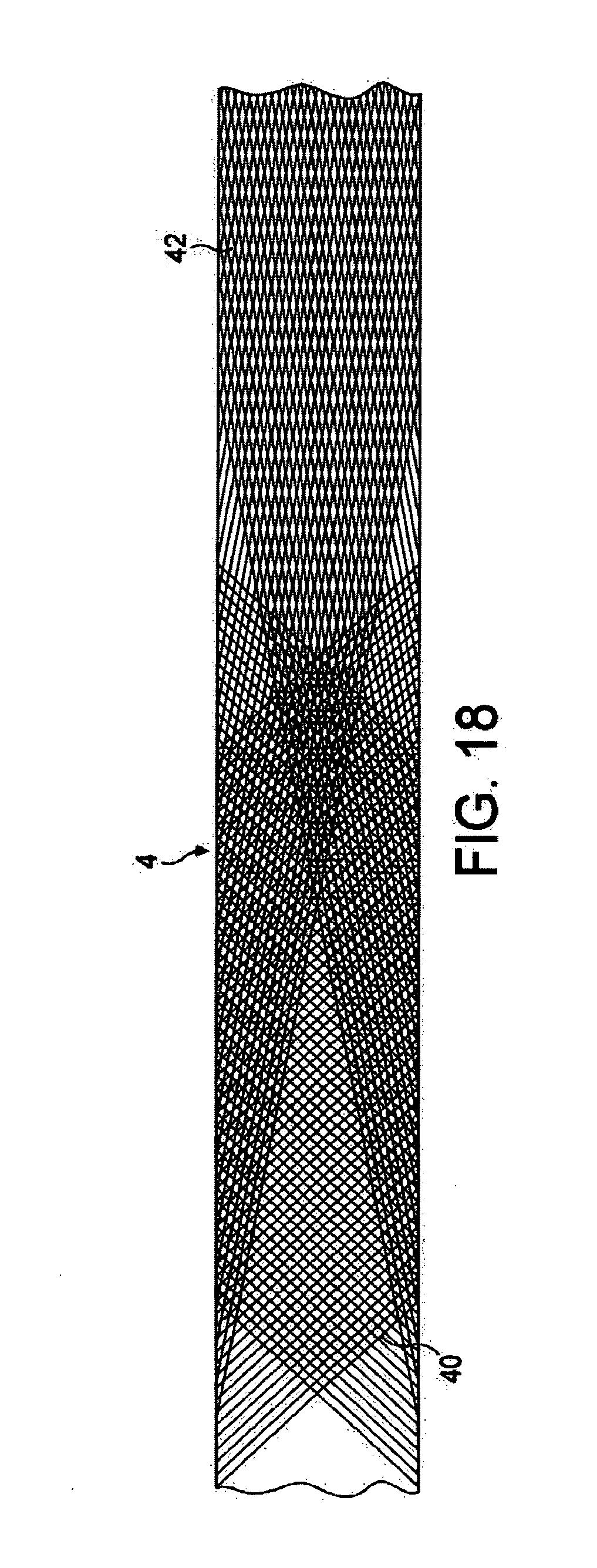
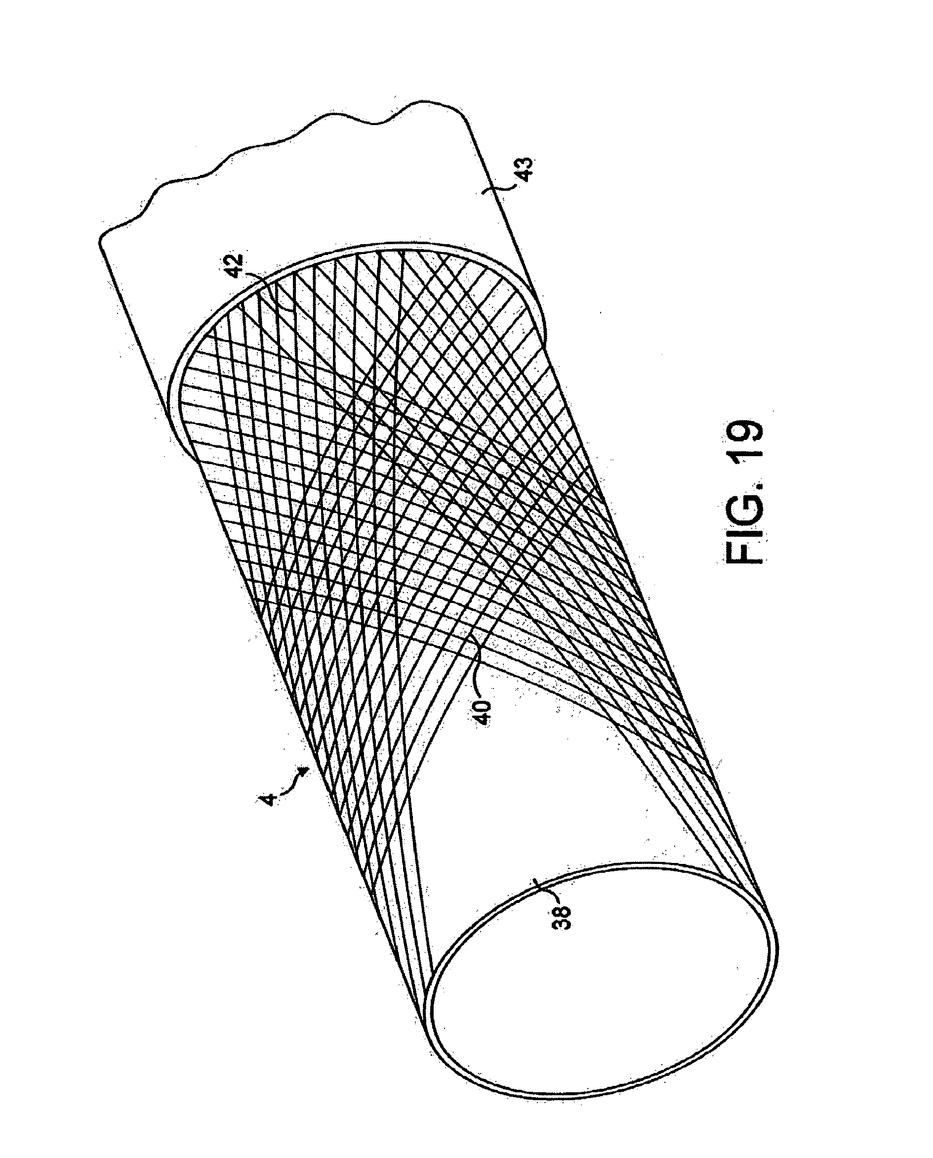
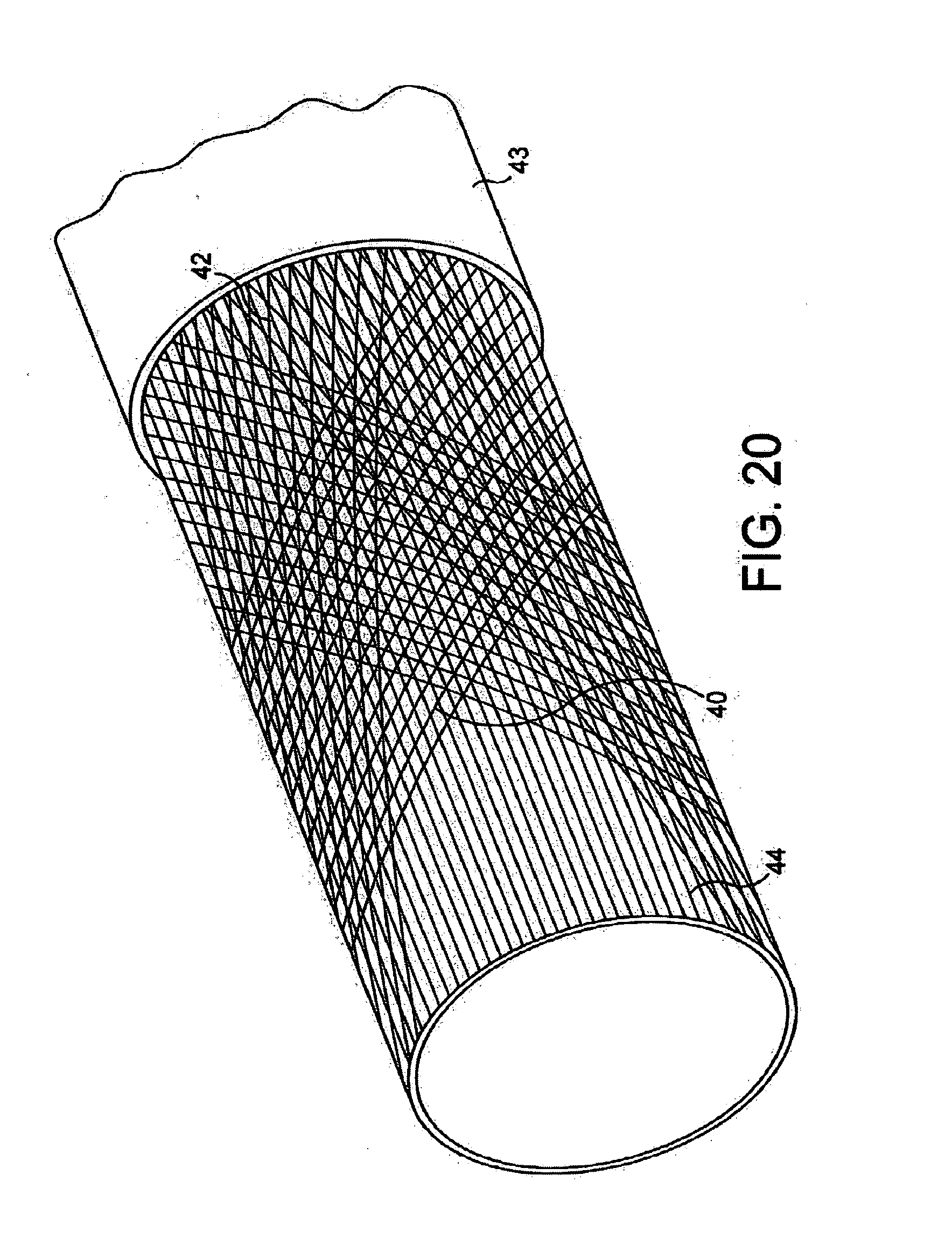
This application is a continuation of application Ser. No. 12/812,946, filed Sep. 16, 2010, which is a national stage of PCT/GB2009/000112, filed Jan. 16, 2009, which claims foreign priority to Appl. No. GB 0819761.8, filed Oct. 28, 2008, and Appl No. GB 0800703.1, filed Jan. 16, 2008, all of which are hereby incorporated by reference in their entireties. This disclosure relates to the temporary support of signs and of other equipment, such as electrical equipment, especially floodlights, above the ground. There are numerous circumstances where signs or other equipment, especially electrical equipment of different kinds, needs temporarily to be mounted on a support above the ground. Examples include temporary traffic signs or signals, public address speakers at a country show or for a travelling circus, satellite dishes for military communication, emergency lighting for roadworks, and temporary floodlights for emergency workers at the site of an accident or for sporting fixtures played after dark or in poor lighting conditions, especially on public grounds. While there have been numerous prior proposals for temporary supports for signs and for electrical and other equipment, mostly in the form of mechanically connectable structures, the structures proposed have often suffered from being too complicated to be readily erectable and demountable by a single person unfamiliar with the structure, too bulky when collapsed to be readily transportable, for example in the boot (trunk) of a small car (automobile), or insufficiently stable. As will become clear from the detailed description below, the present disclosure adopts a different approach. In accordance with a first aspect of this disclosure, equipment is adapted to be temporarily supported above the ground by a self-supporting, readily erectable and transportable mast, the mast comprising: a pneumatically inflatable elongate tube having a first end to which the equipment is coupled and a second end coupled to a ground support tripod, and being provided with bracing structure adapted to brace the tube when inflated and including respective flexible members extending from each tripod leg to the first end of the tube. Preferably the tripod legs are extendable, preferably being telescopic, and are interconnected by bracing struts that may be pushed beyond dead centre to resist unintentional collapse. It will readily be appreciated that a bracing structure formed of flexible members is non-rigid, and so allows the structure as a whole to be packed away for easy transport when not inflated. The principal rigid components of the structure will be the tripod, which, as noted above preferably has telescopic legs to reduce its packing space requirement, and the equipment to be supported. As will become clear from the detailed description below with reference to the accompanying drawings, this enables (say) a temporary floodlight to be transportable in a conventional shoulder bag for erection where required simply by opening the tripod and inflating the tube. The flexible members may each comprise a single or multiple ply cord interconnecting each leg, preferably from a mounting point intermediate its ends when extended, to the first end of the tube, preferably with additional connections to one or more collars mounted on the tube at positions intermediate its ends. The additional connections may comprise respective cords extending from the collar to each said flexible elongate member. Alternatively, each such collar may be provided with three spokes, the proximal ends of which are coupled to the collar, and the distal ends of which are coupled to the cord. For each collar, the distal ends of its spokes are preferably connected by three further cords. When the tube is inflated for use, the cords are each placed under tension, thereby bracing the structure as a whole. In an alternative arrangement, each flexible member may comprise a respective web of material interconnecting a mounting point intermediate the ends of a leg when extended with the first end and the second end of the tube. When the tube is inflated for use and the tripod positioned on the ground, each said web is placed under tension between the first end and the mounting point and between the first and second ends, thereby bracing the structure as a whole. Preferably the tube is flexible when deflated and substantially inflexible when inflated, and includes reinforcing textile strands helically laid between two layers formed from a material selected from rubber, substitutes therefor and plastics, the strands being laid at an angle to the axis of the tubular member of 45°, and more preferably, 30° or less. Preferred embodiments have one or more of the following features: The said material is PVC. The reinforcing strands are formed of a textile material, preferably nylon. The reinforcing strands are helically wound in opposing senses about the axis of the tubular member so as to cross. The reinforcing strands are laid at an angle of between 10 and 15°. The strands with opposing sense may be interwoven, thereby resulting in a woven textile reinforcing structure. There is a second layer of reinforcing strands laid at a different angle to the first. The first layer of reinforcing strands are laid at an angle of between 10 and 15° and the second layer of strands are laid at an angle of about 45°. There is a further layer of reinforcing strands extending parallel to the axis of the tubular member. The term “equipment” as used herein is intended to encompass any form of mechanical or electrical equipment desired to be supported at a height above the ground, including flags, static signs, manually movable signs such as a manual Stop/Go board for controlling traffic flow at road works, sports equipment such as a netball goal or basketball net, and electrically operable equipment of diverse kinds, including, in particular, temporary floodlights flags, electrically operable signs, traffic signals, public address loudspeakers, illuminated road signs, beacons, security, safety or speed cameras, satellite dishes, and television cameras. Embodiments of equipment adapted for temporary support above the ground are hereinafter more particularly described by way of example only with reference to the accompanying drawings, in which: As will be apparent from A pneumatically inflatable elongate tube 4, shown before inflation in A valve 16 is provided for coupling to a pneumatic line 17 connected to pump 3. An electrically operable pump, for example run from a cigar lighter socket in a car (automobile) may be used in place of a manually operable pump. Valve 16 is preferably placed near to the first end of tube 4 so that the mast may only be inflated or deflated when lying on the ground. This avoids the possible problem of electrical equipment falling on someone as the mast is deflated. As can be seen from Elongate flexible members, here in the form of guide lines 22 interconnect the distal ends of the first leg members with disc 19 at the first end 5 of the tube. When the tube 4 is adequately inflated ( An alternative intermediate bracing structure cooperating with guide lines 22 is shown in Tripod 7 may be provided with castors 27 so that the erected mast and equipment may be wheeled into position. The castors are preferably lockable. Since the electrical equipment and mast may be packed away in a shoulder bag for ready transport, and may be erected on site simply by opening the tripod and inflating the tube, transport, erection and taking down can all be performed by a single person without any tools other than a simple pneumatic pump, and without any assembly or disassembly of mechanical parts. Other arrangements are feasible. Thus, as illustrated in While the embodiments illustrated in The elongate tube 4 may be formed from a similar material to that described in our co-pending British Patent Application No: 0501474.1 (published as GB 2422322 A) for use in providing inflatable sports goals. The material suggested in GB 2422322 for forming the tubular struts was natural or synthetic rubber, or plastics substitutes, preferably reinforced with nylon thread. Commercial embodiments of sports goals have since been produced and sold under our Registered Community Trademark igoal®, and are formed with a thickness in the material of the struts of around 2 mm, and a diameter for the goalposts and cross-bar of 3 inches (7.62 cm), and work well when inflated with an applied pressure of around 1 Bar. The tubular members employ inner and outer layers of soft polyvinylchloride (PVC) with nylon threads between the two layers helically wound in opposing senses about the axis of the tube so as to cross, being laid typically with an angle to the axis of 80° or more. The two plastics layers are softened to fuse together in the interstices between the nylon threads. We have found that this structure prevents the tube from ballooning (expanding diametrically) in use. An additional layer of parallel threads preferably runs along the length of the tubular member to prevent stretching lengthwise in use. Elongate tubes formed in the same way work well with the structures described in the present Specification. However, as explained below, and as described and illustrated in our co-pending patent application No: 0819761.8 (not yet published at the date of filing of the present Application), we have found that improved results can be achieved with alternative tubular structures. In In It will be understood that in each of As best shown in For most purposes contemplated by the present invention, we find that a tube 4, as shown in The adoption of tubes 4, especially as shown in Equipment is temporarily supported above the ground by a self-supporting, readily erectable and transportable mast. The mast comprises a pneumatically inflatable elongate tube having a first end to which the equipment is coupled and a second end coupled to a ground support tripod. The mast is provided with bracing structure adapted to brace the tube when inflated and including respective flexible members extending from each tripod leg to the first end of the tube. 1. A tubular member for use as a structural member when inflated to a pressure of between 10 and 20 psi (6.89 to 13.79*104 pascals); the tubular member being flexible when deflated and substantially inflexible when inflated to said pressure, and capable of repeated inflation to said pressure followed by deflation to collapse the tubular member; the tubular member including internal reinforcement strands between an inner layer formed from a material selected from rubber, substitutes therefore and plastics and an outer layer formed from the same material, the internal reinforcement strands including reinforcing textile strands helically laid at an angle to the axis of the tubular member of 30° or less, and the material of the two layers forming a unitary structure as the result of heat softening of the material to cause the material of the two layers to fuse together through spaces between the reinforcement strands. 2. A tubular member according to 3. A tubular member according to 4. A tubular member according to 5. A tubular member according to 6. A tubular member according to 7. A tubular member according to 8. A tubular member according to 9. A method of making a tubular member for use as a structural member when inflated to a pressure of between 10 and 20 psi (6.89 to 13.79*104 pascals); the tubular member being flexible when deflated, substantially inflexible when inflated to said pressure, and capable of repeated inflation to said pressure followed by deflation to collapse the tubular member; the method including the steps of: forming a first layer from a material selected from rubber, substitutes therefor and plastics; forming a reinforcing layer over said first layer, said forming step comprising laying reinforcing strands over the first layer at an angle of 30° or less to the axis of the tubular member; forming a second layer of said material over the reinforcing layer; and heat softening of the material of at least one of the first and second layers to cause the material of the first and second layers to fuse together through spaces between strands of the reinforcing layer to unite the first and second layers into a unitary structure. 10. A method according to 11. A method according to 12. A method according to 13. A method according to 14. A method according to 15. A method according to 16. A method according to 17. A sports goal comprising a plurality of struts interconnected to form nodes with netting optionally attached thereto, the struts including at least: one or more struts defining a crossbar; two or more struts defining respective goal posts; a plurality of ground struts adapted to lie along the ground to define the bottoms of respective left and right sides and a rear of the goal; and bracing struts interconnecting ground struts with the nodes at which crossbar struts and goal post struts are connected to form a corner of the goal, each said strut comprising a tubular member according CROSS-REFERENCE TO RELATED APPLICATIONS
BACKGROUND
SUMMARY OF THE INVENTION
BRIEF DESCRIPTION OF THE DRAWINGS
DESCRIPTION OF PREFERRED EMBODIMENTS