HEAT EXCHANGER FOR VEHICLE
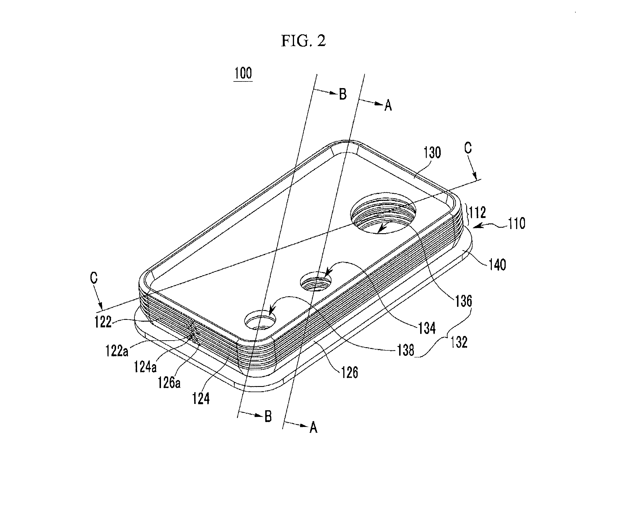
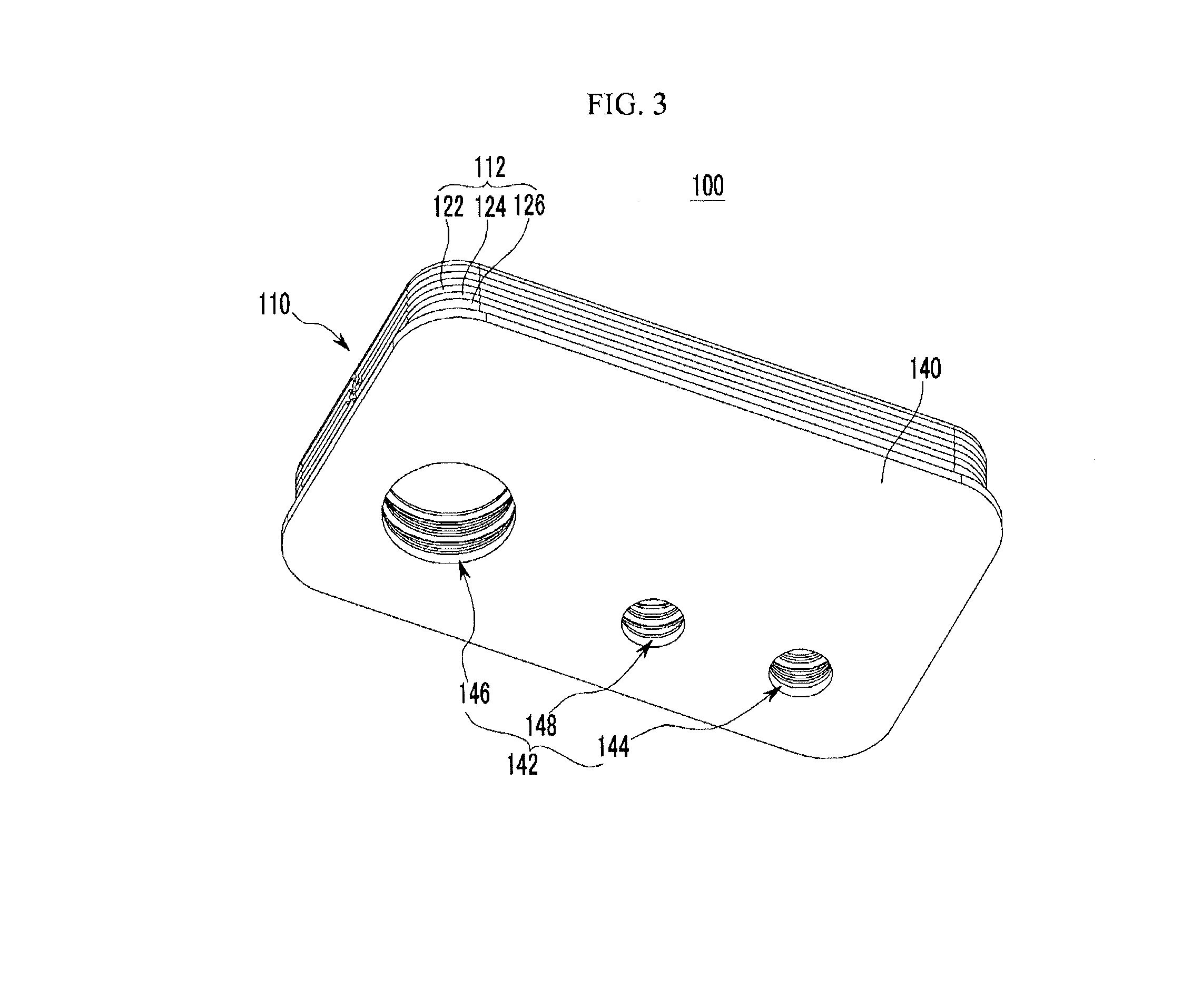
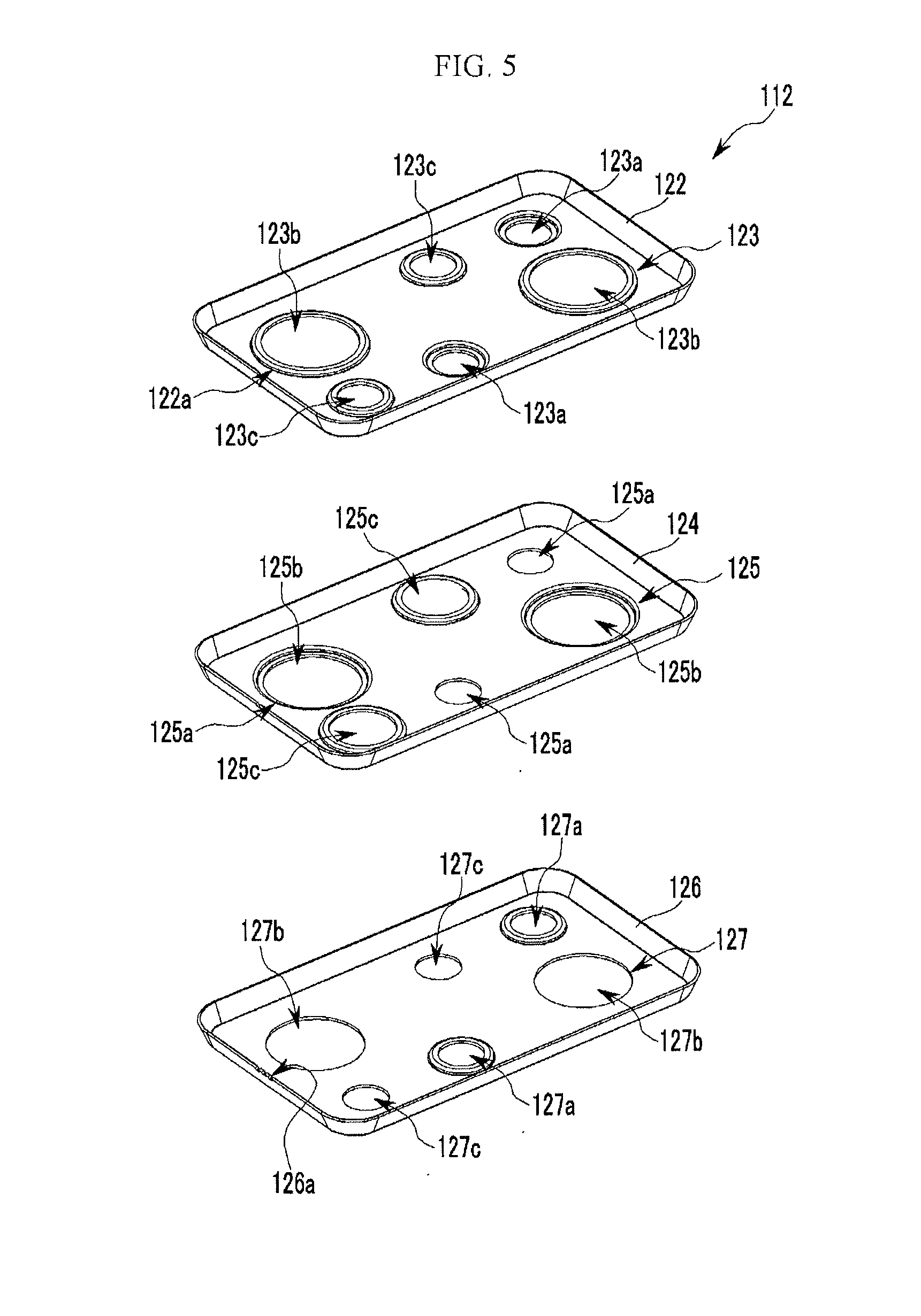
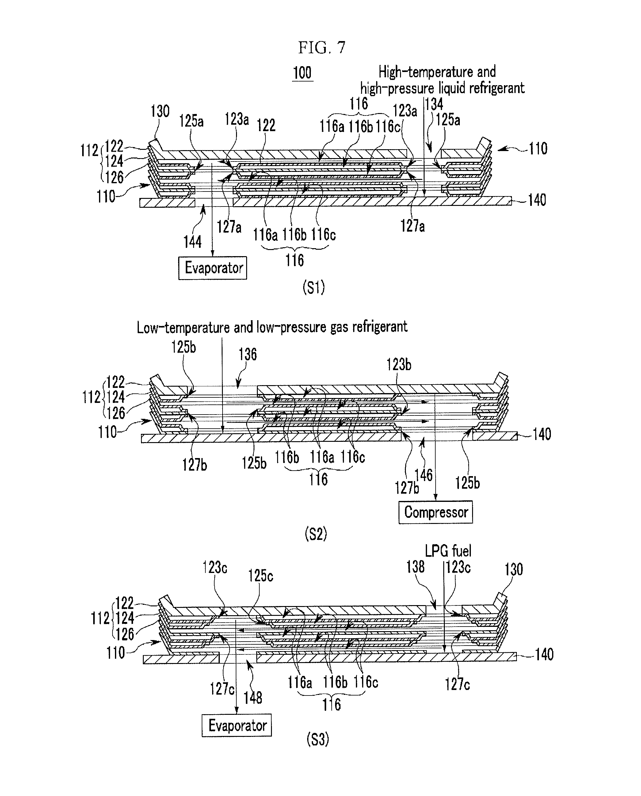
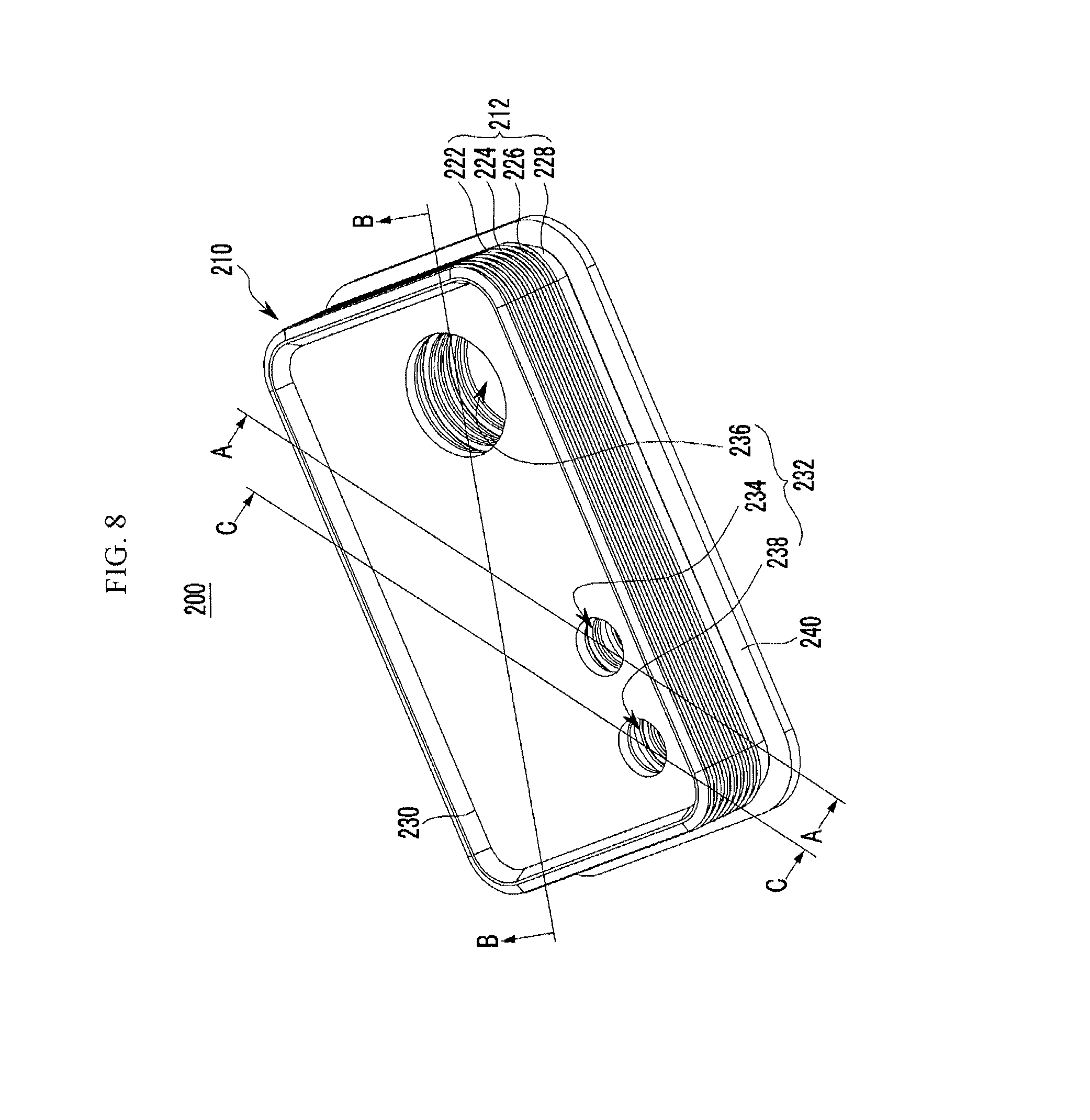
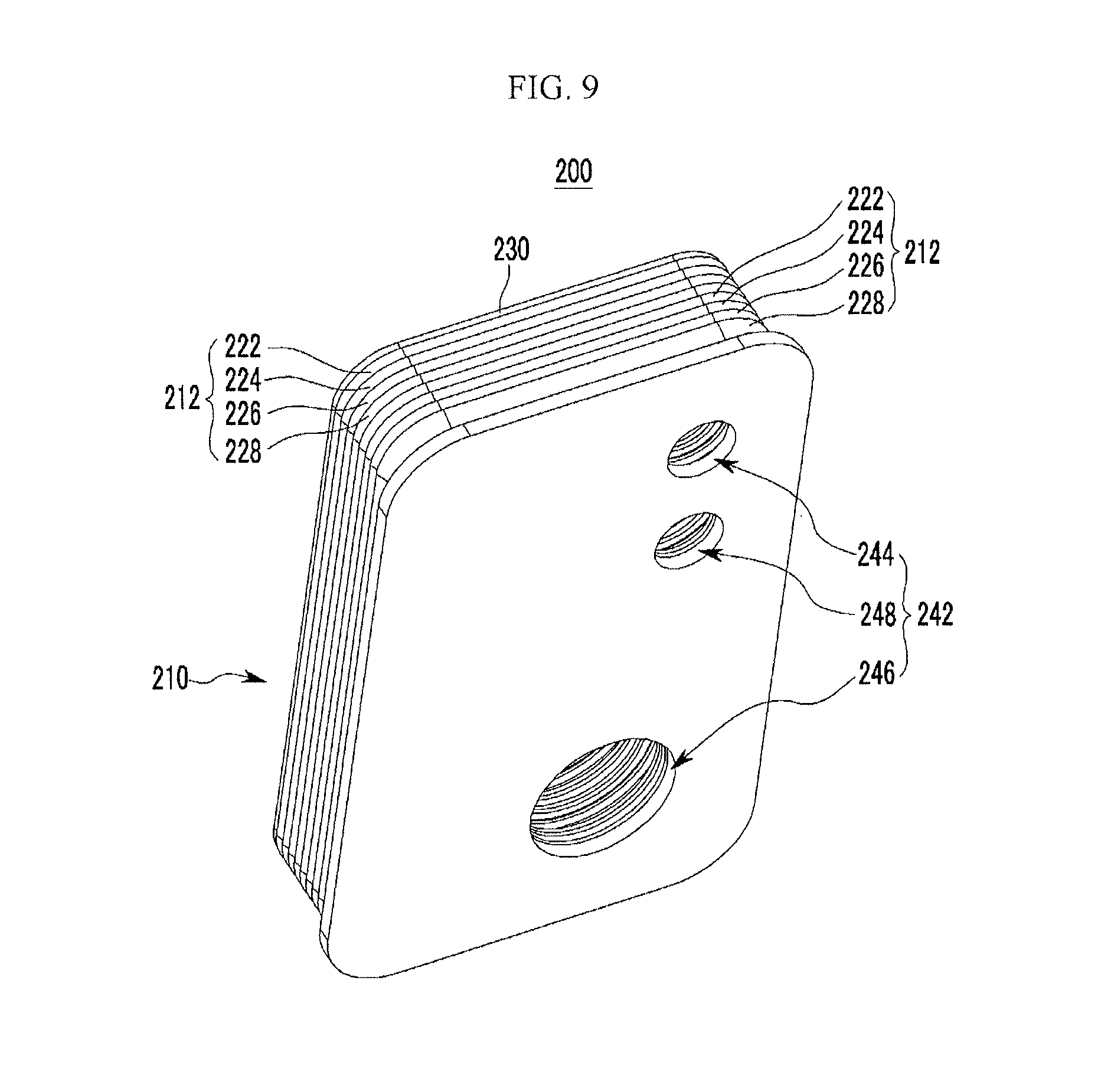
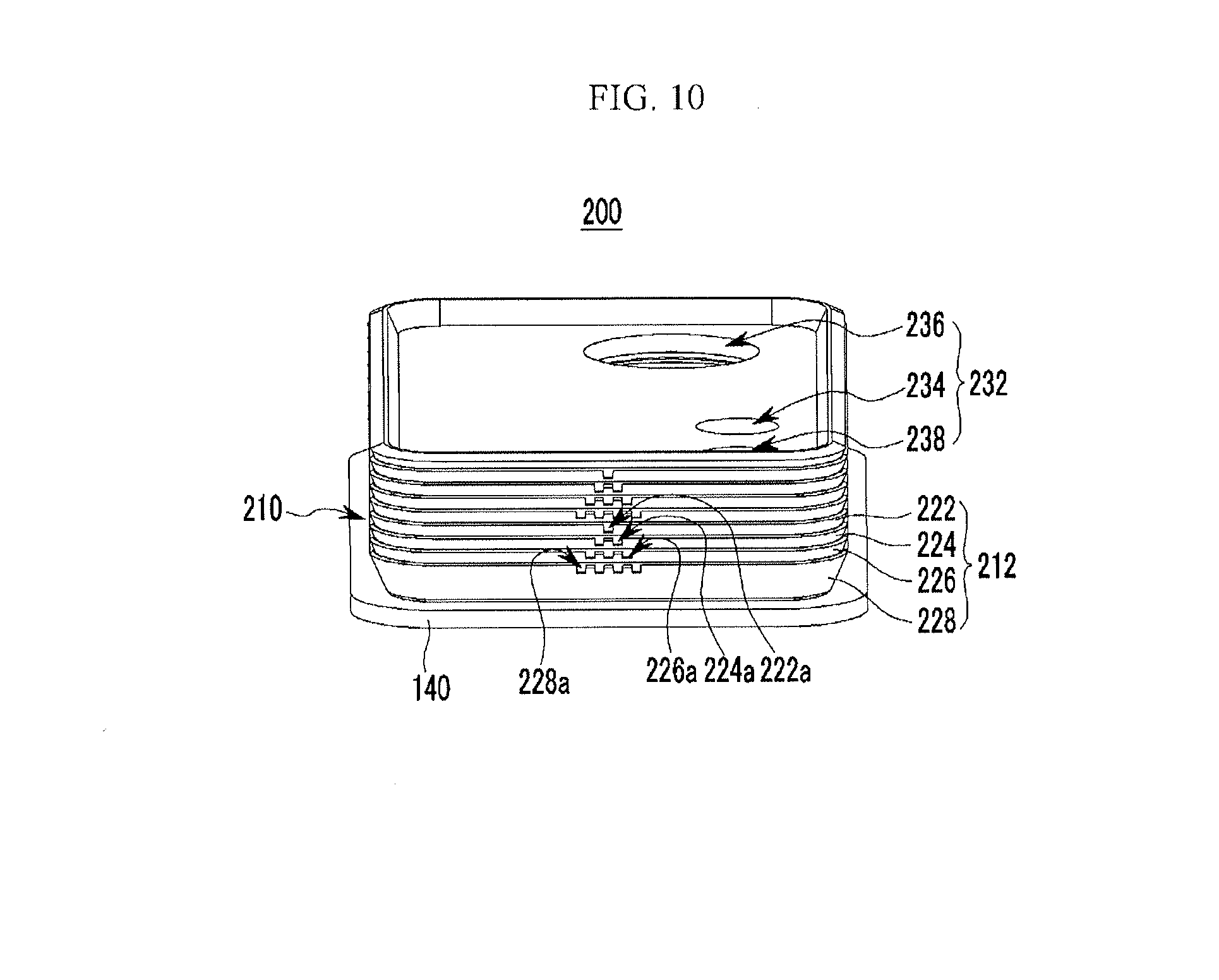
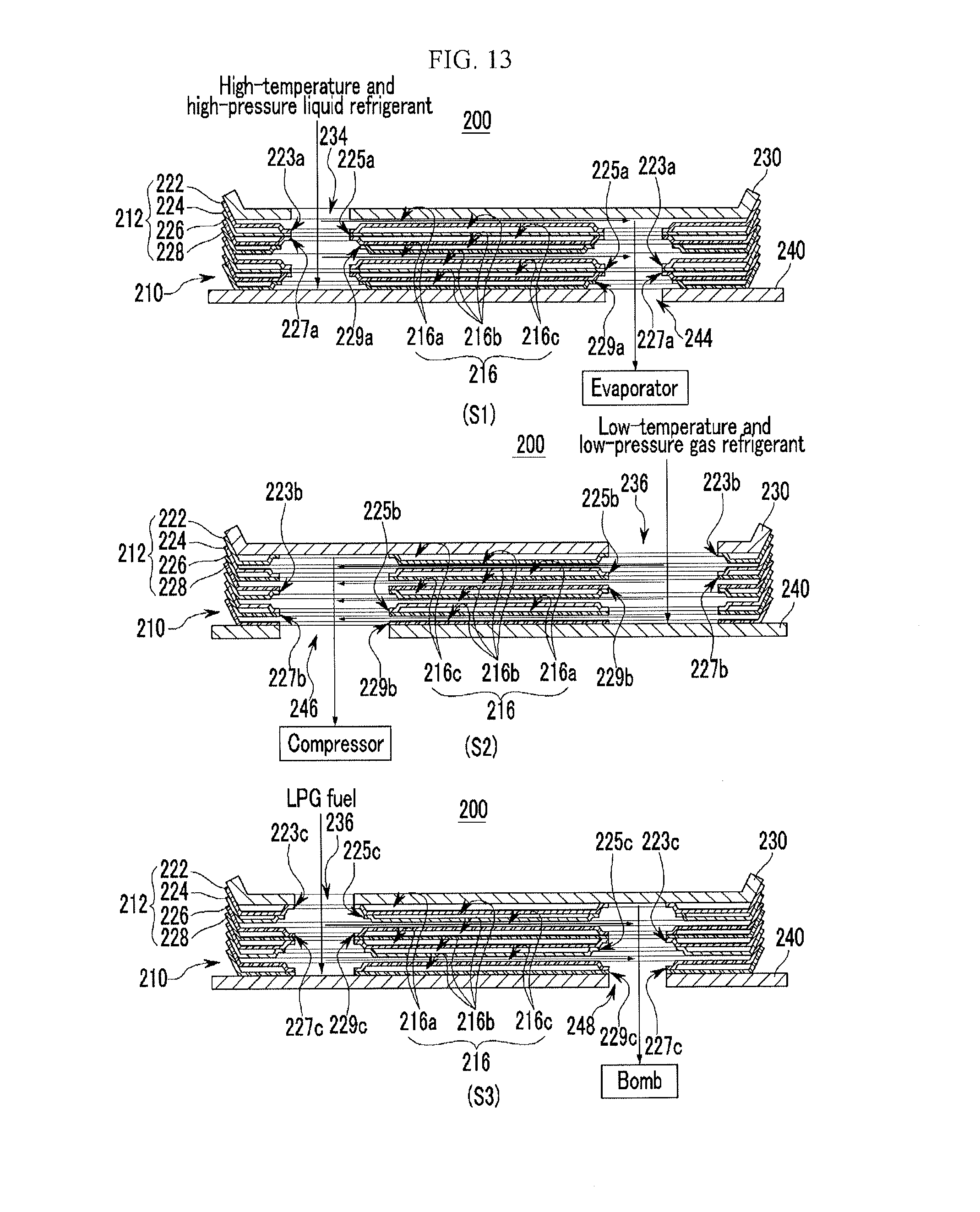
The present application claims priority to Korean Patent Application No. 10-2012-0119953 filed on Oct. 26, 2012, the entire contents of which is incorporated herein for all purposes by this reference. 1. Field of the Invention The present invention relates to a heat exchange for a vehicle. More particularly, the present invention relates to a heat exchanger for a vehicle that efficiently cools LPG fuel by exchanging heat between LPG fuel returned to a bombe from an engine of an LPI vehicle and refrigerant that is circulated in an air-conditioning system. 2. Description of Related Art In general, a liquefied petroleum injection (LPI, an LPG liquefied fuel injection device) engine is an engine (Mono-fuel mode) having a fuel pump installed in a bombe and injects liquefied fuel for each cylinder by using an injector by liquefying LPG fuel at high pressure (5 to 15 bar) by the fuel pump, unlike a mechanical LPG fuel mode that depends on the pressure of a bombe. Since the LPI engine injects liquefied fuel, components such as a vaporizer, a mixer, and the like which are constituent members of a mixer type LPG engine are not required, and the LPI engine includes a high-pressure injector, the fuel pump installed in the bombe, a fuel supply line, an electronic control unit (ECU) exclusively for LPI, and a regulator unit regulating fuel pressure. The electronic control unit of the LPI engine determines a state of the engine by receiving input signals of various sensors and controls a fuel pump, an injector, and an ignition coil for improvement of an optimal air-fuel ratio and engine performance. In addition, the liquefied fuel is supplied to the engine by controlling the fuel pump according to a fuel amount required in the engine, and an LPI injector sequentially injects fuel for each cylinder. However, in a vehicle to which an LPI system in the related art is applied, as high-temperature return fuel is returned to the bombe from the engine, a phenomenon occurs, in which internal pressure of the bombe rises due to an increase in temperature of the LPG fuel. In particular, when the internal pressure of the bombe is higher than charge pressure of a gas station, the LPG fuel cannot be charged in the bombe. As a result, since an additional fuel cooling device needs to be installed in order to decrease the temperature of the fuel returned from the engine, manufacturing and installation costs increase and there is a limit in securing installation space in a narrow engine room. The information disclosed in this Background of the Invention section is only for enhancement of understanding of the general background of the invention and should not be taken as an acknowledgement or any form of suggestion that this information forms the prior art already known to a person skilled in the art. Various aspects of the present invention are directed to providing a heat exchanger for a vehicle that prevents internal pressure of a bombe from increasing by introducing LPG fuel into the bombe while decreasing the temperature of the LPG fuel by exchanging heat between refrigerant that is circulated in an air-conditioning system and LPG fuel returned to a bombe from an engine. In an aspect of the present invention, a heat exchanger apparatus for a vehicle, may include a heat exchanging unit including one or more plate units in which two or more plates are stacked to form different connection channels and exchanging heat with each other while different operating fluids pass through the respective connection channels in the heat exchanging unit, an upper cover mounted on one side of the heat exchanging unit, and including a plurality of inlets that introduce each operating fluid into the heat exchanging unit and are interconnected with the respective connection channels, and a lower cover mounted on the other side of the heat exchanging unit, and including a plurality of outlets that are interconnected with the respective connection channels so as to discharge the each operating fluid passing through the heat exchanging unit. The plate unit may include a first plate coupled with being stacked on the upper cover below the upper cover, and including a first connection channel formed between the first plate and the upper cover and a plurality of connection holes formed to correspond to the respective inlets and the respective outlets, a second plate coupled with being stacked on the first plate below the first plate, and including a second connection channel formed between the second plate and the first plate and a plurality of connection holes formed to correspond to the respective inlets and the respective outlets, and a third plate coupled with being stacked on the second plate below the second plate, and including a third connection channel formed between the third plate and the second plate and a plurality of connection holes formed to correspond to the respective inlets and the respective outlets. The plurality of inlets may include first, second, and third inlets respectively spaced from each other in a length direction of the upper cover and connected with the first, second, and third connection channels through the respective connection holes, wherein the plurality of outlets may include first, second, and third outlets respectively spaced from each other on the lower cover to correspond to the first, second, and third inlets, and connected with the first, second, and third inlets through the first, second, and third connection channels and the respective connection holes. In the first plate, first, second, and third connection holes are formed to correspond to the first, second, and third inlets, and the first, second, and third outlets, respectively, wherein in the second plate, first, second, and third connection holes are formed to correspond to the first, second, and third inlets, and the first, second, and third outlets, respectively, and wherein in the third plate, first, second, and third connection holes are formed to correspond to the first, second, and third inlets, and the first, second, and third outlets, respectively, wherein inner peripheries of the second and third connection holes of the first plate protrude upward and an inner periphery of the first connection hole thereof protrudes downward, wherein an inner periphery of the third connection hole of the second plate protrudes upward and an inner periphery of the second connection hole thereof protrudes downward, wherein an inner periphery of the first connection hole of the third plate protrudes upward, and wherein airtightness of inner peripheries of the respective connection holes is maintained so as to prevent the each operating fluid that flows in the respective connection channels from being mixed. The first inlet is formed at one side in a width direction at the center of the upper cover, and the first outlet is formed at a diagonal corresponding position from the first inlet of the lower cover. The second inlet is formed at one side of the upper cover, and the second outlet is formed at a diagonal corresponding position of the lower cover. The third inlet is formed at one side of the upper cover, and the third outlet is formed at a diagonal corresponding position from the third inlet of the lower cover. The each operating fluid may include medium-temperature and high-pressure liquid refrigerant supplied from a condenser of an air-conditioning system, introduced through the first inlet to pass through the first connection holes and the first connection channels of the respective plates and thereafter, discharged through the first outlets, low-temperature and low-pressure gas refrigerant supplied from an evaporator, introduced through the second inlet to pass through the second connection holes and the second connection channels of the respective plates and thereafter, discharged through the second outlets, and LPG fuel returned to a bombe from an engine of an LPI vehicle, introduced through the third inlet to pass through the third connection holes and the third connection channels of the respective plates and thereafter, discharged through the third outlet. The medium-temperature and high-pressure liquid refrigerant and the LPG fuel flow in the same direction on the first connection channels and the third connection channels, respectively, and the low-temperature and low-pressure gas refrigerant flows in a direction different from the liquid refrigerant and the LPG fuel in the second connection channels. The first outlet is connected with an expansion valve, the second outlet is connected with a compressor, and the third outlet is connected with the bombe in which the LPG fuel is returned and stored. In the first, second, and third plates, first, second, and third verification grooves are formed at sides of the respective plates to verify that the respective plates are sequentially assembled when the respective plates are stacked and coupled with each other. The respective verification grooves may have different numbers. The heat exchanging unit is formed by a plate type in which a plurality of plate units is stacked. The plate unit may include a first plate coupled with being stacked on the upper cover below the upper cover, and including a first connection channel formed between the first plate and the upper cover and a plurality of connection holes formed to correspond to the respective inlets and the respective outlets, respectively, a second plate coupled with being stacked on the first plate below the first plate, and including a second connection channel formed between the second plate and the first plate and a plurality of connection holes formed to correspond to the respective inlets and the respective outlets, respectively, and a third plate coupled with being stacked on the second plate below the second plate, and including a third connection channel formed between the third plate and the second plate, and a plurality of connection holes formed to correspond to the respective inlets and the respective outlets, respectively, and a fourth plate coupled with being stacked on the third plate below the third plate, and including the second connection channel between the fourth plate and the third plate and a plurality of connection holes formed on the fourth plate to correspond to the respective inlets and the respective outlets, respectively. The plurality of inlets may include first, second, and third inlets respectively spaced from each other in a length direction of the upper cover and connected with the first, second, and third connection channels through the respective connection holes, wherein the plurality of outlets may include first, second, and third outlets respectively spaced from each other on the lower cover to correspond to the first, second, and third inlets, and including first, second, and third outlets connected with the first, second, and third inlets through the first, second, and third connection channels and the respective connection holes. In the first plate, first, second, and third connection holes are formed to correspond to the first, second, and third inlets and the first, second, and third outlets, respectively, wherein in the second plate, first, second, and third connection holes are formed to correspond to the first, second, and third inlets and the first, second, and third outlets, respectively, wherein in the third plate, first, second, and third connection holes are formed to correspond to the first, second, and third inlets and the first, second, and third outlets, respectively, wherein in the fourth plate, first, second, and third connection holes are formed to correspond to the first, second, and third inlets and the first, second, and third outlets, respectively, wherein inner peripheries of the second and third connection holes of the first plate protrude upward and an inner periphery of the first connection hole thereof protrudes downward, wherein an inner periphery of the third connection hole of the second plate protrudes upward and an inner periphery of the second connection hole thereof protrudes downward, wherein an inner periphery of the first connection hole of the third plate protrudes upward and an inner periphery of the third connection hole thereof protrudes downward, wherein an inner periphery of the first connection hole of the fourth plate protrudes upward, and wherein airtightness of inner peripheries of the respective connection holes is maintained so as to prevent each operating fluid that flows in the respective connection channels from being mixed. In the first, second, third, and fourth plates, first, second, third, and fourth verification grooves are formed at sides of the respective plates to verify that the respective plates are sequentially assembled when the respective plates are stacked and coupled with each other. The respective verification grooves may have different numbers. The methods and apparatuses of the present invention have other features and advantages which will be apparent from or are set forth in more detail in the accompanying drawings, which are incorporated herein, and the following Detailed Description, which together serve to explain certain principles of the present invention. It should be understood that the appended drawings are not necessarily to scale, presenting a somewhat simplified representation of various features illustrative of the basic principles of the invention. The specific design features of the present invention as disclosed herein, including, for example, specific dimensions, orientations, locations, and shapes will be determined in part by the particular intended application and use environment. In the figures, reference numbers refer to the same or equivalent parts of the present invention throughout the several figures of the drawing. Reference will now be made in detail to various embodiments of the present invention(s), examples of which are illustrated in the accompanying drawings and described below. While the invention(s) will be described in conjunction with exemplary embodiments, it will be understood that the present description is not intended to limit the invention(s) to those exemplary embodiments. On the contrary, the invention(s) is/are intended to cover not only the exemplary embodiments, but also various alternatives, modifications, equivalents and other embodiments, which may be included within the spirit and scope of the invention as defined by the appended claims. An exemplary embodiment of the present invention will hereinafter be described in detail with reference to the accompanying drawings. As those skilled in the art would realize, the described embodiments may be modified in various different ways, all without departing from the spirit or scope of the present invention Throughout the specification, like/similar reference numerals refer to like/similar constituent elements. Throughout the specification, unless explicitly described to the contrary, the word “include” and variation such as “includes” or “including”, will be understood to imply the inclusion of stated elements but not the exclusion of any other elements. Referring to the drawings, a heat exchanger 100 for a vehicle according to the exemplary embodiment of the present invention is applied to an air-conditioning system including a compressor 10 compressing refrigerant, a condenser 20 condensing the compressed refrigerant by receiving the compressed refrigerant from the compressor 10, an expansion valve 30 expanding liquefied refrigerant condensed through the condenser 20, and an evaporator 40 evaporating the refrigerant expanded through the expansion valve 30 through heat-exchange with air. The heat exchanger 100 cools high-temperature LPG fuel returned from an engine 2 in an LPI vehicle using LPG fuel through heat-exchange with refrigerant. To this end, the heat exchanger 100 for a vehicle according to the exemplary embodiment of the present invention includes a heat exchanging unit 110, an upper cover 130, and a lower cover 140, and will be described below in more detail for each component, as illustrated in First, the heat exchanging unit 110 includes a plate unit 112 in which two or more plates are stacked to form different connection channels 116 (see The heat exchanging unit 110 configured as above may be formed by a plate type (alternatively, also referred to as a ‘plate type’) in which a pair of plate units 112 are laminated and coupled with each other or configured by coupling a plurality of plate units, as illustrated in the drawings. A detailed configuration of the plate unit 112 will be described below in more detail. In the exemplary embodiment, the upper cover 130 is mounted on the top of the heat exchanging unit 110, and a plurality of inlets 132 that introduce each operating fluid into the heat exchanging unit 110 and are interconnected with the respective connection channels 116 are formed on the upper cover 130. The lower cover 140 is mounted on the bottom of the heat exchanging unit 110, and a plurality of outlets 142 that are interconnected with the respective connection channels 116 is formed in the lower cover 140 so as to discharge the operating fluids passing through the heat exchanging unit 110 outside. Herein, the plate unit 112 may include a first plate 122, a second plate 124, and a third plate 126, as illustrated in The first plate 122 is coupled with being stacked on the upper cover 130 below the upper cover 130. A first connection channel 116 In the exemplary embodiment, the second plate 124 is coupled with being stacked on the first plate 122 below the first plate 122. A second connection channel 116 The third plate 126 is coupled with being stacked on the second plate 124 below the second plate 124. A third connection channel 116 When the first, second, and third plates 122, 124, and 126 configured as above are stacked and coupled with each other, the first, second, and third plates 122, 124, and 126 are sequentially assembled with each other, and for this, first, second, and third verification grooves 122 The respective verification grooves 122 As a result, a worker may assemble the plate unit 112 by sequentially stacking the first, second, and third plates 122, 124, and 126 through the respective verification grooves 122 Since the worker may easily determine whether the plate unit 112 is misassembled by verifying arrangement of the respective verification grooves 122 Meanwhile, in the exemplary embodiment, the respective inlets 132 are formed apart from the upper cover 130 and include first, second, and third inlets 134, 136, and 138 connected with the first, second, and third connection channels 116 The respective outlets 142 are formed apart from the lower cover 140 to correspond to the first, second, and third inlets 134, 136, and 138, respectively, and include first, second, and third outlets 144, 146, and 148 connected with the first, second, and third inlets 134, 136, and 138 through the first, second, and third connection channels 116 In the exemplary embodiment, the first inlet 134 may be formed at one side in a width direction at the center of the upper cover 130, and the first outlet 144 may be formed at a diagonal corresponding position from the first inlet 134 of the lower cover 140. The second inlet 136 may be formed at one side of the upper cover 130, and the second outlet 146 may be formed at a diagonal corresponding position of the lower cover 140 from the second inlet 136. The third inlet 138 may be formed at the other edge of the upper cover 130, and the third outlet 148 may be formed at one side in a width direction at the center of the lower cover 140 corresponding to a diagonal direction from the third inlet 138. Meanwhile, in the exemplary embodiment, first, second and third connection holes 123 Herein, the first, second, and third connection holes 123 In the exemplary embodiment, first, second and third connection holes 125 Herein, the first, second, and third connection holes 125 First, second and third connection holes 127 Herein, the first, second, and third connection holes 127 Inner peripheries of the second connection hole 123 An inner periphery of the third connection hole 125 An inner periphery of the first connection hole 127 Herein, airtightness of the inner peripheries of the respective connection holes may be maintained so as to prevent the operating fluids that flow on the respective connection channels from being mixed. That is, as illustrated in (a) of As illustrated in (b) of As illustrated in (c) of That is, airtightness of the inner peripheries of the respective connection holes may be maintained so as to prevent the operating fluids that flow on the respective connection channels from being mixed. As a result, when the assembly of the first plate unit 112 is completed with the first, second, and third plates 122, 124, and 126 stacked on each other, the respective operating fluids that flow in the first, second, and third connection channels 116 Herein, the respective operating fluids may include medium-temperature and high-pressure liquid refrigerant supplied from the condenser 20 of the air-conditioning system, low-temperature and low-pressure gas refrigerant supplied from the evaporator 40, and LPG fuel returned from the engine 2. First, the medium-temperature and the high-temperature liquid refrigerant is supplied from the condenser 20 and is introduced into the heat exchanging unit 110 through the first inlet 134. The medium-temperature and high-temperature liquid refrigerant passes through the first connection channel 116 Low-temperature and low-pressure gas refrigerant is supplied from the evaporator 40 and is introduced into the heat exchanging unit 110 through the second inlet 136. The low-temperature and low-pressure gas refrigerant passes through the second connection channel 116 The LPG fuel is returned from the engine 2 to be introduced into the heat exchanging unit 110 through the third inlet 138. The LPG fuel passes through the third connection channel 116 Herein, the medium-temperature and high-pressure liquid refrigerant and the LPG fuel may flow in the same direction on the first connection channel 116 The low-temperature and low-pressure gas refrigerant may flow in an opposite direction to the medium-temperature and high-pressure liquid refrigerant and the LPG fuel passing through the first and second connection channels 116 That is, in the heat exchanging unit 110, the first connection channel 116 As a result, when the medium-temperature and high-pressure liquid refrigerant and the LPG fuel pass through the first connection channel 116 In the exemplary embodiment, the first inlet 134 is connected with the condenser 20, the second inlet 136 is connected with the evaporator 40, and the third inlet 138 is connected with the engine 2 to circulate the respective operating fluids to the first, second, and third connection channels 116 The first outlet 144 is interconnected with the expansion valve 30, the second outlet 146 is interconnected with the compressor 10, and the third outlet 148 is interconnected with the bombe 4 in which the LPG fuel is returned to be stored to supply the respective operating fluids passing through the first, second, and third connection channels 116 Connection ports may be mounted on the respective inlets 134, 136, and 138 and the respective outlets 144, 146, and 148 which are configured above, respectively, and connection hoses or connection pipes are connected to the connection ports to be connected to the air conditioning system, the engine 2, and the bombe 4, respectively. Herein, medium-temperature and high-pressure liquid refrigerant is condensed while non-condensed gas refrigerant included therein exchanges heat with the low-temperature and low-pressure gas refrigerant passing through the second connection channel 116 As a result, the heat exchanging unit 110 minimizes the non-condensed gas refrigerant that exists in the medium-temperature and high-pressure liquid refrigerant and thus supplies the minimized non-condensed gas refrigerant to the expansion valve 30 to increase expansion efficiency and prevent efficiency of the air conditioning system from deteriorating. The LPG fuel is returned to the bombe 4 while the LPG fuel is cooled through exchanging heat with the low-temperature and low-pressure gas refrigerant to prevent internal pressure of the bombe 4 from being increased. Hereinafter, an operation and an action of the heat exchange 100 for a vehicle according to the exemplary embodiment of the present invention configured as above will be described in detail. First, the medium-temperature and high-pressure liquid refrigerant supplied from the condenser 20 is introduced through the first inlet 134 to pass through the first connection channel 116 Low-temperature and low-pressure gas refrigerant supplied from the evaporator 40 is introduced through the second inlet 136 to pass through the second connection channel 116 Herein, medium-temperature and high-pressure liquid refrigerant is cooled to exchange heat with the low-temperature and low-pressure gas refrigerant passing through the second connection channel 116 In this case, the medium-temperature and high-pressure liquid refrigerant flows in an opposite direction to the low-temperature and low-pressure gas refrigerant on each connection channel 116, and as a result, the medium-temperature and high-pressure liquid refrigerant may be more efficiently cooled. Herein, as the medium-temperature and high-pressure liquid refrigerant is disposed to be close to the upper cover 130 and passes through the first connection channel 116 As a result, cooling performance of the air-conditioning system may be prevented from deteriorating due to the increase in temperature of the gas refrigerant. The high-temperature LPG fuel returned from the engine 2 is introduced through the third inlet 138 to pass through the third connection channel 116 Herein, as low-temperature and low-pressure gas refrigerant flows to the second connection channel 116 As such, cooled LPG fuel is discharged through the first outlet 148 to be supplied to the bombe 4. Accordingly, in the heat exchanging unit 100, the high-temperature LPG fuel returned from the engine 2 is cooled to a temperature at an appropriate level through exchanging heat with the low-temperature and low pressure gas refrigerant to be discharged to the bombe 4, and as a result, the internal pressure of the bombe 4 is prevented from being increased due to the introduction of the high-temperature LPG fuel. Meanwhile, as non-condensed gas refrigerant included in the medium-temperature and high-pressure liquid refrigerant is condensed through exchanging heat with the low-temperature and low-pressure gas refrigerant passing through the second connection channel 116 Accordingly, when the heat exchanger 100 for a vehicle according to the exemplary embodiment of the present invention configured as above is applied, the refrigerant circulated in the air-conditioning system and the LPG fuel returned to the bombe 4 exchange heat with each other, and as a result, the LPG fuel is introduced into the bombe 4 while the temperature of the LPG fuel is decreased to thereby prevent the internal pressure of the bombe 4 from being increased. By preventing the internal pressure of the bombe 4 from being increased, fuel is smoothly injected to the bombe 4 and merchantability may be improved at the time of charging fuel. The heat exchanger 100 for a vehicle according to the exemplary embodiment of the present invention is configured by at least one plate type heat exchanger including the plate unit 112 in which two or more plates are stacked, makes the medium-temperature and high-pressure liquid refrigerant supplied from the condenser 20 and the low-temperature and low-pressure gas refrigerant supplied from the evaporator 40 exchange heat with each other therein to prevent performance of the air-conditioning system from deteriorating by improving cooling efficiency of refrigerant by using an overcooling effect and improve cooling performance. By performing overcooling of refrigerant and cooling LPG fuel in a narrow engine room at the same time, spatial utilization may be improved and a layout may be simplified. Meanwhile, a heat exchanger for a vehicle according to another exemplary embodiment of the present invention will be described below with reference to Referring to the drawings, a heat exchanger 200 for a vehicle according to another exemplary embodiment of the present invention is applied to an air-conditioning system including a compressor 10 compressing refrigerant, a condenser 20 condensing the compressed refrigerant by receiving the compressed refrigerant from the compressor 10, an expansion valve 30 expanding liquefied refrigerant condensed through the condenser 20, and an evaporator 40 evaporating the refrigerant expanded through the expansion valve 30 through heat-exchange with air. The heat exchanger 200 for a vehicle according to another exemplary embodiment of the present invention includes a heat exchanging unit 210, an upper cover 230, and a lower cover 240, as illustrated in In the heat exchanging unit 210, one or more plate units 212 in which two or more plates are stacked to form different connection channels 216 (see The heat exchanging unit 210 configured as above may be formed by a plate type (alternatively, also referred to as a ‘plate type’) in which a pair of plate units 212 are stacked and coupled with each other or formed by coupling a plurality of plate units. In another exemplary embodiment of the present invention, the upper cover 230 and the lower cover 240 are mounted on the top and the bottom of the heat exchanging unit 210, respectively. First, second, and third inlets 234, 236, and 238 respectively further from each other are formed in the upper cover 230, and first, second, and third outlets 244, 246, and 248 respectively further from each other are formed in the lower cover 240. Since this is the same as the exemplary embodiment, a detailed description of the configuration and the function will be omitted. Herein, the plate unit 212 according to another exemplary embodiment of the present invention includes a first plate 222, a second plate 224, a third plate 226, and a fourth plate 228, as illustrated in The first plate 222 is coupled with being stacked on the upper cover 230 below the upper cover 230. A first connection channel 216 Herein, the first, second, and third connection holes 223 An inner periphery of the first connection hole 223 Inner peripheries of the second connection hole 223 In another exemplary embodiment, the second plate 224 is coupled with being stacked on the first plate 222 below the first plate 222. A second connection channel 216 Herein, the first, second, and third connection holes 225 An inner periphery of the second connection hole 225 An inner periphery of the third connection hole 225 In another exemplary embodiment, the third plate 226 is coupled with being stacked on the second plate 224 below the second plate 224. A third connection channel 216 Herein, the first, second, and third connection holes 227 An inner periphery of the first connection hole 227 An inner periphery of the second connection hole 227 In another exemplary embodiment, a fourth plate 228 is coupled with being stacked on the third plate 226 below the third plate 226. The second connection channel 216 Herein, the first, second, and third connection holes 229 An inner periphery of the first connection hole 229 As a result, when the assembly of the plate unit 212 is completed with the first, second, third, and fourth plates 222, 224, 226, and 228 stacked on each other, the respective operating fluids that flow in the first, second, and third connection channels 216 That is, the heat exchanging unit 210 according to another exemplary embodiment of the present invention configured as above makes the respective operating fluids to the first, second, and third connection channels 216 Herein, the second connection channel 216 In the plate unit 212 configured as above, first, second, third, and fourth verification grooves 222 The respective verification grooves 222 As a result, the worker may assemble the plate unit 212 by sequentially stacking the respective plates 222, 224, 226, and 228 through the respective verification grooves 222 Since the worker may easily determine whether the plate unit 212 is misassembled by verifying arrangement of the respective verification grooves 222 Meanwhile, in another exemplary embodiment of the present invention, the respective operating fluids may include medium-temperature and high-pressure liquid refrigerant supplied from the condenser 20 of the air-conditioning system, low-temperature and high-pressure gas refrigerant supplied from the evaporator 40, and LPG fuel returned from the engine 2, similarly as the exemplary embodiment. That is, the heat exchanging unit 210 configured as above makes the respective operating fluids to the first, second, and third connection channels 216 Herein, low-temperature and low-pressure gas refrigerant passes through the second connection channel 216 Herein, gas refrigerant exchanges heat with medium-temperature and high-pressure liquid refrigerant and the LPG fuel that pass through the first connection channel 216 Accordingly, the medium-temperature and high-pressure liquid refrigerant and the LPG fuel are cooled through exchanging heat with the low-temperature and low-pressure gas refrigerant and flow in opposite directions to the gas refrigerant to improve heat exchange efficiency. Herein, the non-condensed gas refrigerant included in the medium-temperature and high-pressure liquid refrigerant is condensed while exchanging heat with the low-temperature and low-pressure gas refrigerant passing through the second connection channel 216 As a result, the heat exchanging unit 210 minimizes the non-condensed gas refrigerant that exists in the medium-temperature and high-pressure liquid refrigerant and thus supplies the minimized non-condensed gas refrigerant to the expansion valve 30 to increase expansion efficiency and prevent efficiency of the air conditioning system from deteriorating at the same time. The LPG fuel is returned to the bombe 4 while the LPG fuel is cooled through exchanging heat with the low-temperature and low-pressure gas refrigerant to prevent internal pressure of the bombe 4 from being increased. Hereinafter, an operation and an action of the heat exchange 200 for a vehicle according to another exemplary embodiment of the present invention configured as above will be described in detail. First, the medium-temperature and high-pressure liquid refrigerant supplied from the condenser 20 is introduced through the first inlet 234 to pass through the first connection channel 216 Low-temperature and low-pressure gas refrigerant supplied from the evaporator 40 is introduced through the second inlet 236 to pass through the second connection channel 216 Herein, medium-temperature and high-pressure liquid refrigerant is cooled to exchange heat with the low-temperature and low-pressure gas refrigerant passing through the second connection channel 216 In this case, medium-temperature and high-pressure liquid refrigerant flows in an opposite direction to low-temperature and low-pressure gas refrigerant on the respective connection channels 216 Herein, as the medium-temperature and high-pressure liquid refrigerant is disposed to be close to the upper cover 230 and passes through the first connection channel 216 As a result, cooling performance of the air-conditioning system may be prevented from deteriorating due to the increase in temperature of the gas refrigerant. The high-temperature LPG fuel returned from the engine 2 is introduced through the third inlet 238 to pass through the third connection channel 216 Herein, as low-temperature and low-pressure gas refrigerant flows to the second connection channel 216 In the heat exchanging unit 210, the respective plate units 212 that form a pair are stacked, and as a result, the first connection channels 216 Accordingly, loss of heat transfer is prevented by preventing the medium-temperature and high-pressure liquid refrigerant and the LPG fuel from directly exchanging heat with each other. As a result, the liquid refrigerant and the LPG fuel may be cooled to a temperature at an appropriate level. As such, the LPG fuel cooled to the appropriate level is discharged through the third outlet 248 to be supplied to the bombe 4. Accordingly, in the heat exchanging unit 200, the high-temperature LPG fuel returned from the engine 2 is cooled to a temperature at an appropriate level through exchanging heat between the low-temperature and low-pressure gas refrigerant the medium-temperature and high-pressure liquid refrigerant to be discharged to the bombe 4, and as a result, the internal pressure of the bombe 4 is prevented from being increased due to the introduction of the high-temperature LPG fuel. Meanwhile, as non-condensed gas refrigerant included in the medium-temperature and high-pressure liquid refrigerant is condensed through exchanging heat with the low-temperature and low-pressure gas refrigerant passing through the second connection channel 216 Accordingly, when the heat exchanger 200 for a vehicle according to another exemplary embodiment of the present invention configured as above is applied, refrigerant circulated in the air-conditioning system and the LPG fuel returned to the bombe 4 exchange heat with each other, and as a result, the LPG fuel is introduced into the bombe 4 while the temperature of the LPG fuel is decreased to thereby prevent the internal pressure of the bombe 4 from being increased. By preventing the internal pressure of the bombe 4 from being increased, fuel is smoothly injected to the bombe 4 and merchantability may be improved at the time of charging fuel. The heat exchanger 200 for a vehicle according to the exemplary embodiment of the present invention is configured by at least one plate type heat exchanger including the plate unit 212 in which two or more plates are stacked, makes the medium-temperature and high-pressure liquid refrigerant supplied from the condenser 20 and the low-temperature and low-pressure gas refrigerant supplied from the evaporator 40 exchange heat with each other therein to prevent performance of the air-conditioning system from deteriorating by improving cooling efficiency of refrigerant using an overcooling effect, and improve cooling performance. By performing overcooling of refrigerant and cooling LPG fuel in a narrow engine room at the same time, spatial utilization may be improved and a layout may be simplified. For convenience in explanation and accurate definition in the appended claims, the terms “upper”, “lower”, “inner” and “outer” are used to describe features of the exemplary embodiments with reference to the positions of such features as displayed in the figures. The foregoing descriptions of specific exemplary embodiments of the present invention have been presented for purposes of illustration and description. They are not intended to be exhaustive or to limit the invention to the precise forms disclosed, and obviously many modifications and variations are possible in light of the above teachings. They are not intended to be exhaustive or to limit the invention to the precise forms disclosed, and obviously many modifications and variations are possible in light of the above teachings. as well as various alternatives and modifications thereof. It is intended that the scope of the invention be defined by the Claims appended hereto and their equivalents. A heat exchanger apparatus for a vehicle may include a heat exchanging unit including one or more plate units in which two or more plates are stacked to form different connection channels and exchanging heat with each other while different operating fluids pass through the respective connection channels in the heat exchanging unit, an upper cover mounted on one side of the heat exchanging unit, and including a plurality of inlets that introduce each operating fluid into the heat exchanging unit and are interconnected with the respective connection channels, and a lower cover mounted on the other side of the heat exchanging unit, and including a plurality of outlets that are interconnected with the respective connection channels so as to discharge the each operating fluid passing through the heat exchanging unit. 1. A heat exchanger apparatus for a vehicle, comprising:
a heat exchanging unit including one or more plate units in which two or more plates are stacked to form different connection channels and exchanging heat with each other while different operating fluids pass through the respective connection channels in the heat exchanging unit; an upper cover mounted on one side of the heat exchanging unit, and including a plurality of inlets that introduce each operating fluid into the heat exchanging unit and are interconnected with the respective connection channels; and a lower cover mounted on the other side of the heat exchanging unit, and including a plurality of outlets that are interconnected with the respective connection channels so as to discharge the each operating fluid passing through the heat exchanging unit. 2. The heat exchanger apparatus for the vehicle of a first plate coupled with being stacked on the upper cover below the upper cover, and including a first connection channel formed between the first plate and the upper cover and a plurality of connection holes formed to correspond to the respective inlets and the respective outlets; a second plate coupled with being stacked on the first plate below the first plate, and including a second connection channel formed between the second plate and the first plate and a plurality of connection holes formed to correspond to the respective inlets and the respective outlets; and a third plate coupled with being stacked on the second plate below the second plate, and including a third connection channel formed between the third plate and the second plate and a plurality of connection holes formed to correspond to the respective inlets and the respective outlets. 3. The heat exchanger apparatus for the vehicle of wherein the plurality of inlets includes first, second, and third inlets respectively spaced from each other in a length direction of the upper cover and connected with the first, second, and third connection channels through the respective connection holes, and wherein the plurality of outlets includes first, second, and third outlets respectively spaced from each other on the lower cover to correspond to the first, second, and third inlets, and connected with the first, second, and third inlets through the first, second, and third connection channels and the respective connection holes. 4. The heat exchanger apparatus for the vehicle of wherein in the first plate, first, second, and third connection holes are formed to correspond to the first, second, and third inlets, and the first, second, and third outlets, respectively, wherein in the second plate, first, second, and third connection holes are formed to correspond to the first, second, and third inlets, and the first, second, and third outlets, respectively, and wherein in the third plate, first, second, and third connection holes are formed to correspond to the first, second, and third inlets, and the first, second, and third outlets, respectively, wherein inner peripheries of the second and third connection holes of the first plate protrude upward and an inner periphery of the first connection hole thereof protrudes downward, wherein an inner periphery of the third connection hole of the second plate protrudes upward and an inner periphery of the second connection hole thereof protrudes downward, wherein an inner periphery of the first connection hole of the third plate protrudes upward, and wherein airtightness of inner peripheries of the respective connection holes is maintained so as to prevent the each operating fluid that flows in the respective connection channels from being mixed. 5. The heat exchanger apparatus for the vehicle of 6. The heat exchanger apparatus for the vehicle of 7. The heat exchanger apparatus for the vehicle of 8. The heat exchanger apparatus for the vehicle of medium-temperature and high-pressure liquid refrigerant supplied from a condenser of an air-conditioning system, introduced through the first inlet to pass through the first connection holes and the first connection channels of the respective plates and thereafter, discharged through the first outlets; low-temperature and low-pressure gas refrigerant supplied from an evaporator, introduced through the second inlet to pass through the second connection holes and the second connection channels of the respective plates and thereafter, discharged through the second outlets; and LPG fuel returned to a bombe from an engine of an LPI vehicle, introduced through the third inlet to pass through the third connection holes and the third connection channels of the respective plates and thereafter, discharged through the third outlet. 9. The heat exchanger apparatus for the vehicle of wherein the medium-temperature and high-pressure liquid refrigerant and the LPG fuel flow in the same direction on the first connection channels and the third connection channels, respectively, and wherein the low-temperature and low-pressure gas refrigerant flows in a direction different from the liquid refrigerant and the LPG fuel in the second connection channels. 10. The heat exchanger apparatus for the vehicle of 11. The heat exchanger apparatus for the vehicle of 12. The heat exchanger apparatus for the vehicle of 13. The heat exchanger apparatus for the vehicle of 14. The heat exchanger apparatus for the vehicle of a first plate coupled with being stacked on the upper cover below the upper cover, and including a first connection channel formed between the first plate and the upper cover and a plurality of connection holes formed to correspond to the respective inlets and the respective outlets, respectively; a second plate coupled with being stacked on the first plate below the first plate, and including a second connection channel formed between the second plate and the first plate and a plurality of connection holes formed to correspond to the respective inlets and the respective outlets, respectively; and a third plate coupled with being stacked on the second plate below the second plate, and including a third connection channel formed between the third plate and the second plate, and a plurality of connection holes formed to correspond to the respective inlets and the respective outlets, respectively; and a fourth plate coupled with being stacked on the third plate below the third plate, and including the second connection channel between the fourth plate and the third plate and a plurality of connection holes formed on the fourth plate to correspond to the respective inlets and the respective outlets, respectively. 15. The heat exchanger apparatus for the vehicle of wherein the plurality of inlets includes first, second, and third inlets respectively spaced from each other in a length direction of the upper cover and connected with the first, second, and third connection channels through the respective connection holes, and wherein the plurality of outlets includes first, second, and third outlets respectively spaced from each other on the lower cover to correspond to the first, second, and third inlets, and including first, second, and third outlets connected with the first, second, and third inlets through the first, second, and third connection channels and the respective connection holes. 16. The heat exchanger apparatus for the vehicle of wherein in the first plate, first, second, and third connection holes are formed to correspond to the first, second, and third inlets and the first, second, and third outlets, respectively, wherein in the second plate, first, second, and third connection holes are formed to correspond to the first, second, and third inlets and the first, second, and third outlets, respectively, wherein in the third plate, first, second, and third connection holes are formed to correspond to the first, second, and third inlets and the first, second, and third outlets, respectively, wherein in the fourth plate, first, second, and third connection holes are formed to correspond to the first, second, and third inlets and the first, second, and third outlets, respectively, wherein inner peripheries of the second and third connection holes of the first plate protrude upward and an inner periphery of the first connection hole thereof protrudes downward, wherein an inner periphery of the third connection hole of the second plate protrudes upward and an inner periphery of the second connection hole thereof protrudes downward, wherein an inner periphery of the first connection hole of the third plate protrudes upward and an inner periphery of the third connection hole thereof protrudes downward, wherein an inner periphery of the first connection hole of the fourth plate protrudes upward, and wherein airtightness of inner peripheries of the respective connection holes is maintained so as to prevent each operating fluid that flows in the respective connection channels from being mixed. 17. The heat exchanger apparatus for the vehicle of 18. The heat exchanger apparatus for the vehicle of CROSS-REFERENCE TO RELATED APPLICATION
BACKGROUND OF THE INVENTION
BRIEF SUMMARY
BRIEF DESCRIPTION OF THE DRAWINGS
DETAILED DESCRIPTION