SINTER MOLD MATERIAL, SINTERING AND MOLDING METHOD, SINTER MOLD OBJECT, AND SINTERING AND MOLDING APPARATUS
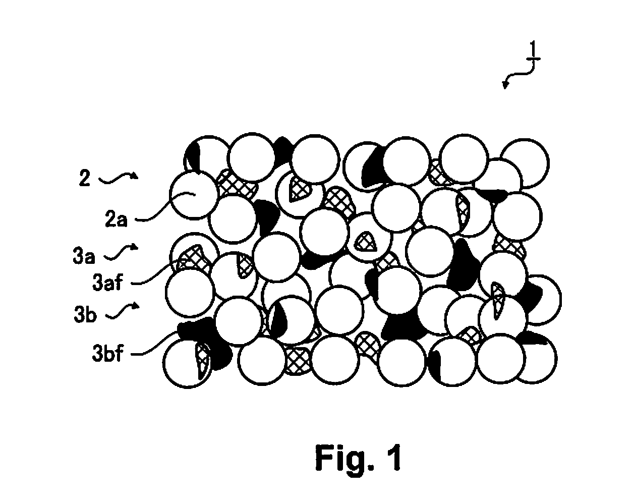
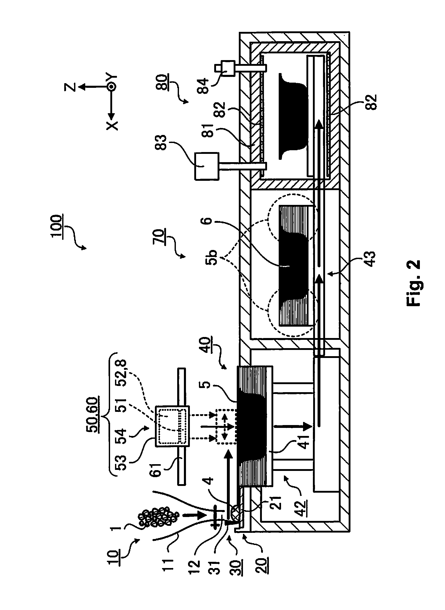
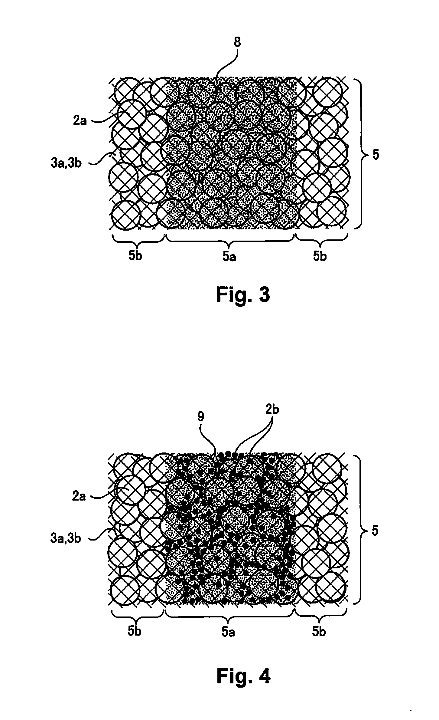
This application claims priority to Japanese Patent Application No. 2014-022002 filed on Feb. 7, 2014. The entire disclosure of Japanese Patent Application No. 2014-022002 is hereby incorporated herein by reference. 1. Technical Field The present invention relates to a sinter mold material, a sintering and molding method, a sinter mold object, and a sintering and molding apparatus. 2. Related Art There is a layer molding method as one method for molding where a solid model (a mold object) with a three dimensional shape is formed. As a layering and molding method, there are proposed, for example, a light molding method where each layer of a cross section of a mold object is formed by selectively curing a photocurable resin using a laser while layering, a powder sintering method where each layer is formed by selectively fusing and solidifying a powder material using a laser while layering, a molten depositing method where each layer is formed due to a thermoplastic material being deposited by being heated and pressed out from a nozzle, a sheet layering method of forming by a sheet material such as paper being cut into the cross sectional shapes of a model and being layered and bonded, and the like. It is disclosed in Japanese Patent No. 2729110 that “a powder material which includes ceramics, a metal, or the like is coated in a layer form. Next, a liquid binding agent which binds together the powder material is discharged onto the layer of the power material using, for example, an ink jet liquid droplet discharge apparatus. A mold object which corresponds to a two dimensional cross sectional layer is formed by the liquid binding agent which penetrates into the spaces between the powder material joining together the powder material. A mold object which has a three dimensional structure is manufactured due to coating of the powder material and discharging of the liquid binding agent are alternately repeated in this manner”. The mold object manufacturing method in Japanese Patent No. 2729110 is a method where the liquid binding agent connects together the powder material and is different to a powder sintering method, where each layer is formed by selectively fusing and solidifying a metal material using a laser, in an aspect where the powder material is joined together. The strength of the mold object in manufacturing methods, where the powder material is connected together using a liquid binding agent as in Japanese Patent No. 2729110, is typically inferior. On the other hand, contraction of the dimensions of the mold object are considerable and it is easy for changes in shape and breakages to occur when sintering is introduced in order to improve the joining together of the powder material in the manufacturing method as in Japanese Patent No. 2729110. That is, there are problems in the mold object manufacturing method in Japanese Patent No. 2729110 in that it is not possible to stabilize forming of a high precision mold object with greater strength. The present invention is carried out in order to solve at least a portion of the problems described above and is able to be realized as the following applied examples and embodiments. A sinter molding material according to the present applied example, which is used a molding method which includes applying liquid droplets to a desired region of the sinter mold material and curing the liquid droplets, includes first inorganic particles, a first thermoplastic binder which bonds together the first inorganic particles, and a second thermoplastic binder which bonds together the first inorganic particles, and an initial temperature of thermal decomposition of the second thermoplastic binder is higher than an initial temperature of thermal decomposition of the first thermoplastic binder. According to the present applied example, the sinter mold material includes the first thermoplastic binder and the second thermoplastic binder which bond together the first inorganic particles. Since the initial temperature of thermal decomposition of the second thermoplastic binder is higher than the initial temperature of thermal decomposition of the first thermoplastic binder, it is possible to provide heating with a wider temperature width with regard to the sinter mold material during molding of the sinter mold object by degreasing and sintering the mold object. The sinter molding material according to the applied example described above where the initial temperature of thermal decomposition of the first thermoplastic binder is 50° C. or more and less than 350° C. According to the present applied example, since the initial temperature of thermal decomposition of the first thermoplastic binder is 50° C. or more and less than 350° C., it is possible for degreasing where the first thermoplastic binder is the target to progress by heating the sinter mold material within a temperature range which exceeds the initial temperature of thermal decomposition of the first thermoplastic binder. The sinter molding material according to the applied example described above where the initial temperature of thermal decomposition of the second thermoplastic binder is 350° C. or more and 750° C. or less. According to the present applied example, since the initial temperature of thermal decomposition of the second thermoplastic binder is 350° C. or more and 750° C. or less, it is possible for degreasing where the second thermoplastic binder is the target to progress by heating the sinter mold material within this temperature range. The sinter molding material according to the applied example described above where it is preferable that the first thermoplastic binder be polyvinyl alcohol, polyvinyl pyrrolidone, poly(meth)methyl acrylate, polyvinyl chloride, ethylene and vinyl acetate copolymer, or polycaprolactone diol. According to the present applied example, it is possible for degreasing where the first thermoplastic binder is the target to progress by heating the sinter mold material at a temperature which exceeds the temperature of the initial temperature of thermal decomposition (from 50° C. to 350° C.) of polyvinyl alcohol, polyvinyl pyrrolidone, poly(meth)methyl acrylate, polyvinyl chloride, ethylene and vinyl acetate copolymer, or polycaprolactone diol. The sinter molding material according to the applied example described above where it is preferable that the second thermoplastic binder be polyethylene, polypropylene, polytetrafluoroethylene, or polybenzimidazole. According to the present applied example, it is possible for degreasing where the second thermoplastic binder is the target to progress by heating the sinter mold material at a temperature which exceeds the temperature of the initial temperature of thermal decomposition (from 350° C. to 750° C.) of polyethylene, polypropylene, polytetrafluoroethylene, or polybenzimidazole. The sinter molding material according to the applied example described above where the first inorganic particles are metal particles. According to the present applied example, since the first inorganic particles are metal particles, it is possible to mold a sinter mold object which is metal. The sinter molding material according to the applied example described above where the first inorganic particles are ceramic particles. According to the present applied example, since the first inorganic particles are ceramic particles, it is possible to mold a sinter mold which is ceramic. The sinter molding material according to the applied example described above where a solvent is included. By the solvent being included in the sinter mold material as in the present applied example, it is possible to more easily obtain the sinter mold material in a paste form where the first inorganic particles are uniformly dispersed. A sintering and molding method according to the present applied example includes forming a fluid mold material by heating a sinter mold material, which includes first inorganic particles, a first thermoplastic binder which bonds together the first inorganic particles, and a second thermoplastic binder which bonds together the first inorganic particles and which has an initial temperature of thermal decomposition which is higher than an initial temperature of thermal decomposition of the first thermoplastic binder, to a temperature which is equal to or more than a melting point of the first thermoplastic binder and a melting point of the second thermoplastic binder, forming a mold layer by spreading the fluid mold material, layering the mold layer, applying liquid droplets to a desired region on the mold layer, forming a mold cross sectional pattern by curing the liquid droplets which are applied to the desired region on the mold layer, finishing a mold object by removing a region, where the liquid droplets are not applied, in the mold layer, carrying out heat treatment on the mold object at a temperature which is less than the initial temperature of thermal decomposition of the second thermoplastic binder, and carrying out sintering treatment on the mold object. The sintering and molding method according to the present applied example includes forming the fluid mold material by heating the sinter mold material, which includes the first inorganic particles and the first thermoplastic binder and the second thermoplastic binder which bond together the first inorganic particles, to a temperature which is equal to or more than the melting point of the first thermoplastic binder and the melting point of the second thermoplastic binder. It is possible to suppress changes in shape and breakages since the sinter mold material which is configured by the first inorganic particles includes the first thermoplastic binder which bonds together the first inorganic particles and the second thermoplastic binder which has a higher initial temperature of thermal decomposition than the first thermoplastic binder. The sintering and molding method according to the applied example described above where the liquid droplets include second inorganic particles. According to the present applied example, the liquid droplets which are applied to a desired region of the mold layer include the second inorganic particles. That is, since the liquid droplets which include the second inorganic particles are applied to a desired region of the mold layer which is formed in the desired cross sectional shape of the mold object, the mold object which is sintered due to degreasing is configured to include the second inorganic particles in addition to the first inorganic particles. That is, it is possible to obtain the mold object where the filling ratio of the inorganic particles is higher compared to a mold object which is configured only by the first inorganic particles. The sintering and molding method according to the applied example described above where the second inorganic particles are metal particles which are the same as the first inorganic particles. According to the present applied example, it is possible to the sinter mold object, for which the effects described above are obtained, using the same metal material. The sintering and molding method according to the applied example described above where the second inorganic particles are ceramic particles which are the same as the first inorganic particles. According to the present applied example, it is possible to the sinter mold object, for which the effects described above are obtained, using the same ceramic material. A sintering and molding apparatus according to the present applied example is provided with a heating section configured to form a fluid mold material by heating a sinter mold material, which includes first inorganic particles, a first thermoplastic binder which bonds together the first inorganic particles, and a second thermoplastic binder which bonds together the first inorganic particles and which has an initial temperature of thermal decomposition which is higher than the initial temperature of thermal decomposition of the first thermoplastic binder, to a temperature which is equal to or more than a melting point of the first thermoplastic binder and a melting point of the second thermoplastic binder, a spreading section configured to form a mold layer by spreading the fluid mold material, a molding section configured to layer the mold layer, a drawing section configured to apply liquid droplets to a desired region on the mold layer which is layered, and a curing section configured to form a mold cross sectional pattern by curing the liquid droplets which are applied to the desired region on the mold layer. The sintering and molding apparatus according to the present applied example is provided with the heating section which forms the fluid mold material by heating the sinter mold material, which includes the first inorganic particles and the first thermoplastic binder and the second thermoplastic binder which bond together the first inorganic particles, to a temperature which is equal to or more than the melting point of the first thermoplastic binder and the melting point of the second thermoplastic binder. It is possible to suppress changes in shape and breakages since the sinter mold material which is configured by the first inorganic particles includes the first thermoplastic binder which bonds together the first inorganic particles and the second thermoplastic binder which has a higher initial temperature of thermal decomposition than the first thermoplastic binder. The sintering and molding apparatus according to the applied example described above further provided with a finishing section configured to finish the mold object by removing a region, where the liquid droplets are not applied, in the mold layer and a sintering section configured to carry out heating and sintering treatment on the mold object. The sintering and molding apparatus according to the present applied example is provided with the finishing section which finishes the mold object by removing a region, where the liquid droplets are not applied, in the mold layer and the sintering section which carries out degreasing and sintering treatment on the mold object. It is possible to finish the mold object by forming a desired cross sectional shape of the mold object and removing a region, where the liquid droplets are not applied, in the mold layer which is layered due to the desired region of the mold layer which is layered being cured. A sinter mold object according to the present applied example is molded using the sinter mold material which is described as an example in any of applied example 1 to applied example 8. The sinter mold object which is molded using the sinter mold material described in the applied examples described above is proposed as a sinter mold object with higher precision on the basis of more stable production and more stable quality. A sinter mold object according to the present applied example is molded using the sintering and molding method which is described as an example in any of applied example 9 to applied example 12. The sinter mold object which is molded using the sintering and molding material described in the applied examples described above is proposed as a sinter mold object with higher precision on the basis of more stable production and more stable quality. A sinter mold object according to the present applied example is configured to include first inorganic particles which are included beforehand in a sinter mold material which is to be layered and second inorganic particles which are included in liquid droplets which are applied to the sinter mold material which is layered. According to the present applied example, the sinter mold object is configured to include the first inorganic particles which are included beforehand in the sinter mold material which is to be layered and the second inorganic particles which are included in the liquid droplets which are applied to the sinter mold material which is layered. That is, since the sinter mold object is configured to include the second inorganic particles in addition to the first inorganic particles, it is possible to obtain the sinter mold object where the filling ratio of the inorganic particles is higher compared to a sinter mold object which is configured only by the first inorganic particles. Referring now to the attached drawings which form a part of this original disclosure: Embodiments which formulate the present invention will be described below with reference to the drawings. Below is one embodiment of the present invention and the embodiment does not limit the present invention. Here, in order for the description to be easy to understand, there are cases the dimensions in the following diagrams are different to the actual dimensions. As embodiment 1, a “sinter mold material”, a “sintering and molding apparatus”, and a “sintering and molding method” which uses the sinter mold material and the sintering and molding apparatus will be described with respect to layer molding as one technique of molding a three dimensional solid model (a sinter mold object). As the method for layer molding, a method is used where a mold object is formed by selectively applying liquid droplets using an ink jet system to a thin layer which is configured by a sinter mold material which is to be formed into the cross sectional shape of the mold object and consecutively layering the portions where the liquid droplets are applied while curing. Below, the details of this will be described. The sinter mold material 1 is a material (principal component) which is used when molding a three dimensional solid model (a sinter mold object) using a layer molding method and layers (referred to below as mold layers), which are for forming each layer which becomes the base for a sinter mold object, that is, each cross sectional shape of the mold object, are formed using the sinter mold material 1. The sinter mold material 1 is configured using a powder material 2 which is formed from “first inorganic particles” which are a powder, a binder material 3 The powder material 2 is a main constituent material of the sinter mold object which is formed using the sinter mold material 1. The powder material 2 is configured as an aggregate of the inorganic particles 2 It is possible to use metal particles or ceramic particles as the inorganic particles 2 In addition, it is preferable that the particle diameter of the inorganic particles 2 In addition, it is preferable that the powder material 2 includes the inorganic particles 2 In a case where the particle diameters of the inorganic particles 2 A stainless steel alloy powder is used in the powder material 2 (the inorganic particles 2 The binder materials 3 For example, polycaprolactone diol, where the melting point is 55° C. to 58° C. and the initial temperature of thermal decomposition is 200° C., is used as the binder material 3 The binder material 3 The binder material 3 For example, polyethlene, where the melting point is 120° C. and the initial temperature of thermal decomposition is 400° C., is used as the binder material 3 Here, a binder material where the initial temperature of thermal decomposition is lower than the sintering temperature of the inorganic particles 2 The binder material 3 Precision of the shape of the sinter mold object increases as the filling ratio of the particles which configure the powder material 2 in the sinter mold object increases. Therefore, it is preferable to have mixing proportions where the volume which is taken up by the binder materials 3 The sinter mold material 1 according to the present embodiment is formed by mixing a stainless steel alloy powder as (A) the powder material 2, polycaprolactone diol as (B) the binder material 3 Here, a solvent may be included in the sinter mold material 1. A water-based solvent, which includes water and an organic solvent such as an aqueous solution of a mineral salt, is preferable as the solvent. It is even more preferable that water is used as the water-base solvent. It is possible to more easily obtain the sinter mold material in paste form where the powder material 2 is uniformly dispersed by a solvent being included in the sinter mold material 1. In addition, since it is easier to spread the sinter mold material in paste form using the solvent, it is possible for the layers (the mold layers) for layering of the sinter mold material to be more thinly formed in the layer molding method. In addition, a water soluble organic solvent may be added into the water-base solvent. For example, there are the examples of alcohols such as methanol, ethanol, butanol, IPA (isopropyl alcohol), N-propyl alcohol, butanol, isobutanol, TBA (tert-butanol), butanediol, ethyl hexanol, and benzyl alcohol, glycol ethers such as 1,3 dioxolane, ethylene glycol dimethyl ether, ethylene glycol dimethyl ether, propylene glycol monomethyl ether, ethylene glycol monomethyl ether, ethylene glycol monomethyl ether, and ethylene glycol monomethyl ether acetate, glycols such as ethylene glycol, diethylene glycol, triethylene glycol, and propylene glycol, ether solvents such as isopropyl ether, methyl cellosolve, cellosolve, butyl cellosolve, dioxane, MTBE (methyl tertiary butyl ether), and butyl carbitol. Due to a water soluble organic solvent being added, it is possible to more easily obtain the sinter mold material in paste form where the powder material 2 is uniformly dispersed. In addition, since it is easier to spread the sinter mold material in paste form using the solvent, it is possible for the layers (the mold layers) for layering of the sinter mold material to be more thinly formed in the layer molding method. The sinter mold material 1 according to the present embodiment is formed by kneading a stainless steel alloy powder as (A) the powder material 2, polyvinyl alcohol as (B) the binder material 3 In The sintering and molding apparatus 100 is an apparatus which uses the sinter mold material 1 to mold the three dimensional solid model (the sinter mold object) using a layer molding method. The sintering and molding apparatus 100 is provided with a material supplying section 10, a heating section 20, a spreading section 30, a molding section 40, a drawing section 50, a curing section 60, a finishing section 70, a degreasing and sintering section 80, a control section (which is not shown in the diagram) which controls each of the sections, and the like. The material supplying section 10 is a section which supplies the sinter mold material 1 which is contained therein to the heating section 20 and is provided with, for example, a hopper 11 as shown in Here, the material supplying section 10 is not limited to this configuration and may be a configuration (which is not shown in the diagram) where, for example, a loading section which loads and heats a cartridge which contains the sinter mold material 1 is provided and the sinter mold material 1 is supplied to the heating section 20 due to the sinter mold material 1 having fluidity by the cartridge which is filled being heated to a temperature which is equal to or higher than the melting points of the binder materials 3 The heating section 20 is provided with a hot plate 21 where the sinter mold material 1 is heated to and maintained at a temperature which is equal to or higher than the melting points of the binder materials 3 The spreading section 30 is provided with a squeegee 31. The squeegee 31 is a long and thin plate body which extends in the Y axis direction and which is provided to be able to move in the X axis direction, and it is possible for the fluid mold material 4 to be thinly spread by the fluid mold material 4 being moved over the X-Y plane so as to be pushed in the −X direction. The spreading section 30 spreads the fluid mold material 4 on a stage 41 which is provided in the molding section 40 and forms a mold layer 5. Here, the method for thinly spreading the fluid mold material 4 is not limited to the method of spreading using the squeegee 31. For example, a method of spreading by pressurizing using air, a method of spreading using centrifugal force by rotating a stage which is provided with a heating section, or the like may be used. The molding section 40 is provided with the stage 41, a stage raising and lowering mechanism 42 which raises and lowers the stage 41 in the Z axis direction, and the like. At an initial position where the stage 41 is positioned on the same plane (the same height) as the hot plate 21, the stage 41 configures the X-Y plane over which the fluid mold material 4 is spread using the squeegee 31. The stage 41 is maintained at room temperature, and the fluid mold material 4 which is spread on the stage 41 loses fluidity as the temperature becomes less than the melting points of the binder materials 3 The stage raising and lowering mechanism 42 lowers the stage 41 according to the layer thickness of the mold layer 5 which is spread and formed on the stage 41. By lowering the stage 41, the surface of the mold layer 5 is positioned on the same plane (same height) as the hot plate 21, and the X-Y plane, where the fluid mold material 4 is spread using the squeegee 31 and is layered as the mold layer 5, is configured again. The drawing section 50 is provided with a discharge head 51, a cartridge loading section 52, a carriage 53, a carriage moving mechanism 54 (which is not shown in the diagram), and the like. The discharge head 51 is provided with a nozzle (which is not shown in the diagram) which discharges ultraviolet ray curable ink (UV ink 8) as “liquid droplets” using an ink jet system onto the mold layer 5 on the stage 41. The cartridge loading section 52 is loaded with an ink cartridge which contains the UV ink 8 and supplies the UV ink 8 to the discharge head 51. The carriage 53 is mounted with the discharge head 51 and the cartridge loading section 52 (that is, an ink cartridge) and is moved on the upper surface of the stage 41 using the carriage moving mechanism 54. The carriage moving mechanism 54 has an X-Y axis linear transporting mechanism and moves (scans) the carriage 53 over the X-Y plane. The drawing section 50 forms a desired image (an image which reflects the cross sectional shape of the sinter mold object) on the mold layer 5 which is spread on the stage 41 using the UV ink 8 due to being controlled by the controlling section. In detail, the control section has image information on each cross sectional layer which configures the sinter mold object which is input in advance, controls the positions over which the discharge head 51 is moved and the timing with which the UV ink 8 is discharged according to the image information, and correspondingly applies the UV ink 8 to each of the mold layers 5. The curing section 60 is provided with an ultraviolet ray irradiating unit 61 as a light irradiating means which cures the UV ink 8 which is applied to the mold layer 5. The finishing section 70 is a portion which finishes a mold object 6 by removing a region (a non-mold section 5 Here, since it is sufficient if the finishing treatment uses a method of washing away and removing the non-mold section 5 The degreasing and sintering section 80 is a portion which degreases the mold object 6 where the non-mold section 5 Here, a configuration, where the sintering and molding apparatus 100 is provided with the finishing section 70 and the degreasing and sintering section 80 to be continuous from the molding section 40, is described as an example, but the present invention is not limited to this. For example, the finishing section 70 and the degreasing and sintering section 80 may be separately configured or each of the finishing section 70 and the degreasing and sintering section 80 may be separately configured. A sintering and molding method where the sinter mold material 1 and the sintering and molding apparatus 100 described above are used will be described next. The sintering and molding method according to the present embodiment includes the following. (1) forming the fluid mold material 4 by heating the sinter mold material 1, which includes the inorganic particles 2 (2) spreading the fluid mold material 4 and forming the mold layer 5 by cooling to a temperature which is less than the melting points of the binder materials 3 (3) layering the mold layers 5 (4) applying the UV ink 8 to a desired region of the mold layer 5 which is layered (5) curing the UV ink 8 which is applied to the desired region of the mold layer 5 (6) finishing the mold object 6 by removing a region, where the UV ink 8 is not applied, in the mold layer (7) carrying out degreasing treatment on the mold object 6 (8) carrying out sintering treatment on the mold object 6 The sintering and molding method will be described below in order with reference to Here, from after supplying the sinter mold material 1 to the sintering and molding apparatus 100 to performing sintering treatment of the mold object 6 is performed according to controlling by the control section which is provided in the sintering and molding apparatus 100. First, the sinter mold material 1, which includes the inorganic particles 2 Next, the sinter mold material 1 is supplied from the material supplying section 10 to the heating section 20 (the hot plate 21). The amount of the sinter mold material 1 which is supplied to the heating section 20 at one time is controlled to be an amount which is equivalent to one layer of the mold layer 5. The heating section 20 heats the sinter mold material 1 to a temperature which is equal to or higher than the melting points of the binder materials 3 Next, the fluid mold material 4 is spread on the stage 41 using the spreading section 30. In detail, the sinter mold material 1 (the fluid mold material 4) is pushed and stretched over the surface of the stage 41 by the squeegee 31, which abuts with the +X side of the sinter mold material 1 (the fluid mold material 4) which takes on fluidity, being moved in the −X direction. The stage 41 is maintained at room temperature and the fluid mold material 4 which is spread on the stage 41 is cooled to room temperature. Due to the fluid mold material 4 being cooled to room temperature, the binder materials 3 The layer thickness of the mold layer 5 is controlled according to the specifications of the spreading using the squeegee 31. In detail, it is desirable that appropriate setting be performed so as to have the desired thickness since the layer thickness of the mold layer 5 changes due to the size of the gap between the lower edge of the squeegee 31 and the X-Y plane (for example, the surface of the stage 41 at an initial position), the movement speed of the squeegee 31, the viscosity of the fluid mold material 4, and the like. Next, the drawing section 50 forms a desired image on the mold layer 5, which is formed on the stage 41, using the UV ink 8. In detail, the UV ink 8 is applied to positions which correspond to the cross sectional shape of the sinter mold object by the UV ink 8 being discharged while the discharge head 51 is moved according to image information on each cross sectional layer which configures the sinter mold object which is input into the control section in advance. Due to the binder materials 3 Next, the curing section 60 cures the UV ink 8 which is applied to the mold layer 5. In detail, the mold section 5 Here, in order to maintain interface joining strength with the UV ink 8 which is applied to the mold layer 5 which is layered next, irradiating of ultraviolet rays and curing to the extent that photo-polymerization is not complete is preferable when curing the UV ink 8. In addition, the sintering and molding apparatus 100 may be configured so that the ultraviolet ray irradiating unit 61 is mounted in the carriage 53 and there may be a method of irradiating of ultraviolet rays and curing while the UV ink 8 is being applied. Next, the stage raising and lowering mechanism 42 lowers the stage 41 according to the layer thickness of the mold layer 5 which is formed by being spread on the stage 41. Due to the stage 41 being lowered, the surface of the mold layer 5 is positioned on the same surface of the hot plate 21 and an X-Y plane, where the fluid mold material 4 is spread using the squeegee 31 and is layered as the mold layer 5, is configured again. After this, from supplying the sinter mold material 1 from the material supplying section 10 to the heating section 20 to lowering of the stage 41 is repeated and the mold layer 5 is layered. That is, the second time onward of the mold layer 5 is layered on the mold layer 5 which is previously formed Here, there may be a method where forming of the mold layer 5 by spreading the fluid mold material 4 is performed at a location other than on the stage 41 and the mold layer 5 is layered by being sequentially transferred to the stage 41. If the layered is completed so that the layering of the mold layers 5 reaches a height which corresponds to the molding of the mold object 6, the final product is taken out from the molding section 40 and the mold object 6 is finished. In detail, the mold object 6 is finished by the mold object (the layer object with the mold layers 5) being transported from the molding section 40 to the finishing section 70 using the transporting mechanism 43 and the non-mold section 5 Next, the mold object 6 which is finished is moved to the degreasing and sintering section 80 and degreasing treatment is carried out. In detail, first, the mold object 6 is transported from the finishing section 70 to an inner section of the degreasing and sintering furnace 81 using the transporting mechanism 43 and degreasing of the mold object 6 is performed. Degreasing is performed with an aim of finally heating and decomposing the binder materials 3 Next, sintering treatment is performed on the mold object 6 where the binder material 3 As described above, it is possible for the following effects to be obtained according to the sinter mold material, the sintering and molding method, the sinter mold object, and the sintering and molding apparatus of the present embodiment. The sinter mold material 1 includes the binder materials 3 In addition, since the initial temperature of thermal decomposition of the binder material 3 In more detail, since the initial temperature of thermal decomposition of the binder material 3 In addition, since the initial temperature of thermal decomposition of the binder material 3 It is possible to more easily obtain the sinter mold material 1 in paste form where the inorganic particles 2 That is, according to the sinter mold material, the sintering and molding method, and the sintering and molding apparatus of the present embodiment, it is possible for the sinter mold material 1 to be easily spread in the state where scattering of the inorganic particles 2 A sintering and molding method and a sinter mold object according to embodiment 2 will be described next. Here, in the description, the same reference numerals are used for the configuration parts which are the same as the embodiment described above and overlapping description is omitted. Embodiment 2 is where “liquid droplets” includes “second organic particles”. The sintering and molding method of embodiment 2 only differs with regard to the point where UV ink 9 is used as the UV ink 8 which is used in embodiment 1 and the other configuration parts are the same as the sintering and molding method of embodiment 1. The UV ink 9 is ultraviolet ray curable ink where the inorganic particles 2 It is preferable that the metal particles or ceramic particles, which are the same as the inorganic particles 2 The inorganic particles 2 Beyond this, the same processes as the sintering and molding method of embodiment 1 is performed and a sinter mold object is obtained. It is possible for the following effects to be obtained in addition to the effects of the embodiment described above according to the sintering and molding method and the sinter mold object of the present embodiment. The UV ink 9 which is applied to a desired region of the mold layer 5 includes the inorganic particles 2 In understanding the scope of the present invention, the term “comprising” and its derivatives, as used herein, are intended to be open ended terms that specify the presence of the stated features, elements, components, groups, integers, and/or steps, but do not exclude the presence of other unstated features, elements, components, groups, integers and/or steps. The foregoing also applies to words having similar meanings such as the terms, “including”, “having” and their derivatives. Also, the terms “part,” “section,” “portion,” “member” or “element” when used in the singular can have the dual meaning of a single part or a plurality of parts. Finally, terms of degree such as “substantially”, “about” and “approximately” as used herein mean a reasonable amount of deviation of the modified term such that the end result is not significantly changed. For example, these terms can be construed as including a deviation of at least ±5% of the modified term if this deviation would not negate the meaning of the word it modifies. While only selected embodiments have been chosen to illustrate the present invention, it will be apparent to those skilled in the art from this disclosure that various changes and modifications can be made herein without departing from the scope of the invention as defined in the appended claims. Furthermore, the foregoing descriptions of the embodiments according to the present invention are provided for illustration only, and not for the purpose of limiting the invention as defined by the appended claims and their equivalents. A sintering and molding method includes forming a fluid mold material by heating a sinter mold material, which includes inorganic particles, a binder material and a binder material which bond together the inorganic particles, to a temperature equal to or more than the melting points of the binder materials, forming a mold layer by spreading the fluid mold material, layering a mold layer, applying UV ink to a desired region on the mold layer, forming a mold cross sectional pattern by curing the UV ink which is applied to a desired region on the mold layer, finishing a mold object by removing a region, where the UV ink is not applied, in the mold layer, carrying out heat treatment on the mold object at a temperature which is less than the initial temperature of thermal decomposition of the binder material, and carrying out sintering treatment on the mold object. 1. A sinter molding material, which is used a molding method which includes applying liquid droplets to a desired region of the sinter mold material and curing the liquid droplets, the sinter mold material comprising:
first inorganic particles; a first thermoplastic binder which bonds together the first inorganic particles; and a second thermoplastic binder which bonds together the first inorganic particles, an initial temperature of thermal decomposition of the second thermoplastic binder being higher than an initial temperature of thermal decomposition of the first thermoplastic binder. 2. The sinter molding material according to the initial temperature of thermal decomposition of the first thermoplastic binder is 50° C. or more and less than 350° C. 3. The sinter molding material according to the initial temperature of thermal decomposition of the second thermoplastic binder is 350° C. or more and 750° C. or less. 4. The sinter molding material according to the first thermoplastic binder is polyvinyl alcohol, polyvinyl pyrrolidone, poly(meth)methyl acrylate, polyvinyl chloride, ethylene and vinyl acetate copolymer, or polycaprolactone diol. 5. The sinter molding material according to the second thermoplastic binder is polyethylene, polypropylene, polytetrafluoroethylene, or polybenzimidazole. 6. The sinter molding material according to the first inorganic particles are metal particles. 7. The sinter molding material according to the first inorganic particles are ceramic particles. 8. The sinter molding material according to 9. A sintering and molding method comprising:
forming a fluid mold material by heating a sinter mold material, which includes first inorganic particles, a first thermoplastic binder which bonds together the first inorganic particles, and a second thermoplastic binder which bonds together the first inorganic particles and which has an initial temperature of thermal decomposition which is higher than an initial temperature of thermal decomposition of the first thermoplastic binder, to a temperature which is equal to or more than a melting point of the first thermoplastic binder and a melting point of the second thermoplastic binder; forming a mold layer by spreading the fluid mold material; layering the mold layer; applying liquid droplets to a desired region on the mold layer; forming a mold cross sectional pattern by curing the liquid droplets which are applied to the desired region on the mold layer; finishing a mold object by removing a region, where the liquid droplets are not applied, in the mold layer; carrying out heat treatment on the mold object at a temperature which is less than the initial temperature of thermal decomposition of the second thermoplastic binder; and carrying out sintering treatment on the mold object. 10. The sintering and molding method according to the liquid droplets include second inorganic particles. 11. The sintering and molding method according to the second inorganic particles are metal particles which are the same as the first inorganic particles. 12. The sintering and molding method according to the second inorganic particles are ceramic particles which are the same as the first inorganic particles. 13. A sintering and molding apparatus comprising:
a heating section configured to form a fluid mold material by heating a sinter mold material, which includes first inorganic particles, a first thermoplastic binder which bonds together the first inorganic particles, and a second thermoplastic binder which bonds together the first inorganic particles and which has an initial temperature of thermal decomposition which is higher than an initial temperature of thermal decomposition of the first thermoplastic binder, to a temperature which is equal to or more than a melting point of the first thermoplastic binder and a melting point of the second thermoplastic binder; a spreading section configured to form a mold layer by spreading the fluid mold material; a molding section configured to layer the mold layer; a drawing section configured to apply liquid droplets to a desired region on the mold layer which is layered; and a curing section configured to form a mold cross sectional pattern by curing the liquid droplets which are applied to the desired region on the mold layer. 14. The sintering and molding apparatus according to a finishing section configured to finish the mold object by removing a region, where the liquid droplets are not applied, in the mold layer, and a sintering section configured to carry out heating and sintering treatment on the mold object. 15. A sinter mold object which is molded using the sinter mold material according to 16. A sinter mold object which is molded using the sintering and molding method according to 17. A sinter mold object comprising:
first inorganic particles which are included beforehand in a sinter mold material which is to be layered; and second inorganic particles which are included in liquid droplets which are applied to the sinter mold material which is layered.CROSS-REFERENCE TO RELATED APPLICATIONS
BACKGROUND
SUMMARY
BRIEF DESCRIPTION OF THE DRAWINGS
DETAILED DESCRIPTION OF EXEMPLARY EMBODIMENTS
Embodiment 1
Sinter Mold Material
Powder Material
Binder Material
Mixing Proportions
Applied Example
Applied Example
Sintering and Molding Apparatus
Sintering and Molding Method
Embodiment 2
GENERAL INTERPRETATION OF TERMS