QUAD LAYER PASSAGE VARIABLE GEOMETRY TURBINE FOR TURBOCHARGERS IN EXHAUST GAS RECIRCULATION ENGINES
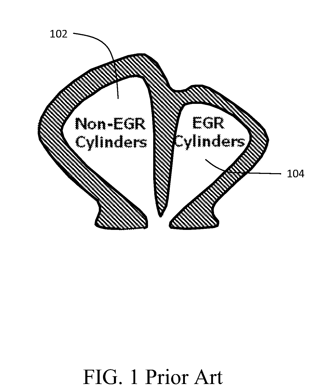
1. Field of the Invention This invention relates generally to the field of charge air boosting of internal combustion engines employing exhaust gas recirculation for emissions reduction and more particularly to a variable geometry turbine employing a four passage divided volute where two paired passages provide the necessary pressure differential to drive EGR, and the other two paired passages are relieved of the EGR-driving pressure differential requirement. 2. Description of the Related Art Exhaust Gas Recirculation (EGR) has been the main technology used for NOx reduction in diesel engines in countries with stringent NOx emission targets. As Selective Catalytic Reduction (SRC) technology efficiency improves, it is supplanting EGR as the prime NOx reduction technology. However, SCR requires significant and wide spread infrastructure to support replenishment of urea for SCR engines as well as sophisticated sensor and control systems for On-Board Diagnostics (OBD) to prevent operators from tampering or circumventing the emissions control system. Unfortunately, implementation of significant amounts of EGR result in a fuel consumption (and CO2 emission) penalty. The fuel consumption penalty is caused by the negative pressure gradient from the intake manifold to the exhaust manifold and the resulting pumping loss to the engine. As such, engine manufacturers have strived to innovate new boosting system technologies that are able to drive EGR while minimizing the fuel consumption penalty associated with the negative pressure gradient. The main technology that has been used to create the negative pressure gradient while also maintaining the proper air/fuel ratio has been various types of Variable Geometry Turbocharger (VGT). A VGT provides a method of creating the appropriate negative pressure gradient while at the same time, increasing the boost so that additional gas flows through the engine. The additional gas is the diluent-cooled EGR. The EGR is additive to the fresh air that is needed for proper combustion, thus the total flow through the engine is increased. To increase the total flow through the engine, the density of the charge in the intake manifold must be increased, thus resulting in higher boost requirements from the boosting system. As VGT is expensive and adds more failure modes to the engine system, some manufacturers have opted to use wastegated turbochargers, but with unequal volutes on the divided turbine housing; first volute 102 for receiving exhaust from engine cylinders not incorporating EGR and second volute 104 receiving exhaust from engine cylinders incorporating EGR as shown in It is therefore desirable to provide a variable geometry turbine for use with EGR which does not require a wastegate. It is additionally desirable to separately control EGR flow and boost. The embodiments of the present application describe a variable geometry turbine for turbochargers in exhaust gas recirculation engines which incorporates a turbine housing having an exhaust inlet with a first side receiving exhaust from cylinders having exhaust gas recirculation (EGR) and a second side receiving exhaust from non-EGR cylinders. The first side has a first EGR-driving passage and a second EGR-driving passage and the second side having a first non-EGR-driving passage and a second non-EGR-driving passage. A first control valve is associated with the second EGR-driving passage and a second control valve is associated with the second non-EGR-driving passage. A controller is adapted to control the first and second control valves. The embodiments provide a method for exhaust recirculation control wherein exhaust is drawn from a plurality of non-EGR cylinders in an engine with a first exhaust manifold and exhaust is drawn from a plurality of EGR cylinders in the engine with a second exhaust manifold. Exhaust is received from the first exhaust manifold in a turbine exhaust inlet with a first side having a first EGR-driving passage and a second EGR-driving passage connected to the first exhaust manifold. Exhaust is controlled between the first EGR-driving passage and the second EGR-driving passage with a first control valve associated with the second EGR-driving passage to control back pressure for EGR flow. Exhaust is received from the second exhaust manifold in a second side of the turbine exhaust inlet having a first non-EGR-driving passage and a second non-EGR-driving passage connected to the second manifold. Exhaust flow is controlled between the first non-EGR-driving passage and the second non-EGR-driving passage with a second control valve associated with the second non-EGR-driving passage to control boost. These and other features and advantages of the present invention will be better understood by reference to the following detailed description when considered in connection with the accompanying drawings wherein: The embodiments described herein provide a low cost VGT that utilizes multiple volutes and valves to control the flow to the various volutes. The volutes are sized to provide different flow characteristics and thus provide true variable geometry turbine functionality. The embodiments receive 100% of the exhaust gases for EGR from one portion or bank of the engine's cylinders while allowing the remaining cylinders operate without the negative pressure gradient constraints necessary for EGR. For descriptive purposes, passages, volutes, or manifolds connected to the cylinders providing EGR-driving pressure differential will be defined as “EGR-driving passages”, “EGR-driving volutes” and “EGR-driving manifolds” while passages, volutes or manifolds connect to the cylinders which do not provide EGR-driving pressure differential will be defined as “non-EGR-driving passages”, “non-EGR-driving volutes” and “non-EGR-driving manifolds”. The embodiment, characterized as a Quad Layer Passage (QLP) volute can enhance an EGR emission control system by providing additional control of the EGR and boost level independently. To maximize the QLP volute for asymmetrical boosting, four passages are provided in a divided exhaust inlet into the turbine housing 300 of the turbocharger with an inlet flange 301 of the four passage divided exhaust inlet 302 is shown in A second side 310 of the exhaust inlet 302 also has two passages with different A/r. The smaller non-EGR-driving passage 312 and associated volute 412 is designed to provide the necessary power to the turbine to provide the desired air flow when maximum EGR is required. In prior art devices, a wastegate would be provided to lower the boost when less air flow was required, but as the name indicates, that is a wasteful method of control. In the present embodiment, the second non-EGR-driving passage 314 and associated volute 414 has a larger A/r and an associated control valve, as will be described in greater detail subsequently. When less boost is required, flow is allowed to flow into larger A/r second non-EGR-driving passage 314 as well as the smaller passage 312, thus reducing the power production of the turbine 404 while also reducing the back pressure without requiring a wastegate. A schematic diagram of a diesel engine system 700 employing the disclosed embodiment is shown in At the exit 710 of an EGR cooler 712, the gas flow is the EGR flow being returned to the engine. A valve 714 controls EGR flow into the engine. The flow at the exit 710 may be expressed as: An inlet manifold 716 receives the charge air flow from the charge air cooler 704 and the EGR cooler 712 through EGR mixer 717 and the gas flow is a combination of the charge air and EGR and may be expressed as: For the example engine a 6 cylinder structure is employed with cylinders 718 The combined outlet of first EGR-driving passage 306 and second EGR driving passage 308 will have one half of the engine flow, which consists of air, fuel and EGR, but has the total EGR flow split off prior to entering the turbine. The combined outlet of the volutes 412 and 414 from first non-EGR-driving passage 312 and second non-EGR-driving passage 314 will have one half of the engine flow, but it will be split by the control valve 504 between a smaller and larger passage. The total flow is In consideration for the EGR flow requirements controlled by control valve 502 altering back pressure by adjusting flow between EGR-driving passages 306 and 308, the flow from the non-EGR-driving manifold 720 will be split by the control valve 504 into non-EGR-driving passages 312 and 314 to achieve flow in the volutes 412 and 414 fir the correct total power from the turbine 724, which produces the desired total air flow from the compressor 706 to the engine. The embodiments disclosed minimize the impact of EGR on the engine pumping loop. The boosting system uses a combination of the Quad Layer Passage Variable Geometry Turbine and the Asymmetrical Volute Boosting system in a configuration that drives all the EGR from the second bank of cylinders 718 Control of the QLP volute variable geometry turbine is accomplished by a controller 802 as shown in Back pressure for controlling EGR flow in the engine and overall boost provided by the turbocharger to the engine are controlled using the first and second. control valves 502, 504, The mutual operation of the control valves to provide EGR rate control and boost control is demonstrated in For sizing of the EGR and non-EGR-driving passage and volute pairs, the different corrected flows and expansion ratios are calculated for each of the four volutes. For each operating point of the turbocharger based on engine demand, the compressor is matched first. The compressor power is calculated for the corrected flow, pressure ratio and efficiency of the compressor. This total power must be produced b the turbine stage. Before calculating the turbine requirements, the pressure gradient that is required for the EGR flow rate is calculated from the EGR cooler and piping flow characteristics. This pressure gradient is added to the boost pressure of the compressor to arrive at the required EGR driving pressure in exhaust manifold 722 in All the Expansion Ratio/Corrected Flow operating points for the EGR small passage are plotted. The point requiring the lowest corrected flow/exhaust recirculation (ER) point is chosen as the design point. The small volute on the EGR bank is sized to produce this flow. The size of the combined large and small volutes on the EGR bank is chosen to match the largest corrected flow/ER point. After the flows and expansion ratio of the EGR-driving passages and associated volutes are known, the turbine power resulting from that portion of turbine flow can he calculated. The non-EGR-driving passages and associated volutes must provide the difference between the required compressor power plus bearing loss and the power produced by the EGR bank of flow. The small non-EGR-driving passage and associated volute is sized to provide the turbine power for maximum EGR with maximum required engine boost. The large non-EGR-driving passage and associated volute is sized to provide appropriate reduction in the expansion ratio for the minimum boost condition. Having now described the invention in detail as required by the patent statutes, those skilled in the art will recognize modifications and substitutions to the specific embodiments disclosed herein. Such modifications are within the scope and intent of the present invention as defined in the following claims. A variable geometry turbine for turbochargers in exhaust gas recirculation engines incorporates a turbine housing having an exhaust inlet with a first side receiving exhaust from cylinders having exhaust gas recirculation (EGR) and a second side receiving exhaust from non-EGR cylinders. The first side has a first EGR-driving passage and a second EGR-driving passage and the second side having a first non-EGR-driving passage and a second non-EGR-driving passage. A first control valve is associated with the second EGR-driving passage and a second control valve is associated with the second non-EGR-driving passage. A controller is adapted to control the first and second control valves. 1. A variable geometry turbine for turbochargers in exhaust gas recirculation engines comprising:
a turbine housing having an exhaust inlet with a first side receiving exhaust from cylinders having exhaust gas recirculation (EGR) and a second side receiving exhaust from non-EGR cylinders, said first side having a first EGR-driving passage and a second EGR-driving passage and said second side having a first non-EGR-driving passage and a second non-EGR-driving passage; a first control valve associated with the second EGR-driving passage; a second control valve associated with the second non-EGR-driving passage; and, a controller adapted to control the first and second control valves. 2. The variable geometry turbine for turbochargers in exhaust gas recirculation engines as defined in 3. The variable geometry turbine for turbochargers in exhaust gas recirculation engines as defined in 4. The variable geometry turbine for turbochargers in exhaust gas recirculation engines as defined in 5. The variable geometry turbine for turbochargers in exhaust gas recirculation engines as defined in 6. The variable geometry turbine for turbochargers in exhaust gas recirculation engines as defined in 7. The variable geometry turbine for turbochargers in exhaust gas recirculation engines as defined in 8. The variable geometry turbine for turbochargers in exhaust gas recirculation engines as defined in 9. The variable geometry turbine for turbochargers in exhaust gas recirculation engines as defined in 10. An engine with exhaust gas recirculation (EGR) comprising:
a plurality of non-EGR cylinders with a first exhaust manifold; a plurality of EGR cylinders with a second exhaust manifold; a turbocharger having a compressor; a turbine connected to drive the compressor with a turbine housing having an exhaust inlet with a first side connected to the first exhaust manifold and a second side connected to the second manifold, said first side having a first non-EGR-driving passage and a second non-EGR-driving passage and said second side having a first EGR-driving passage and a second EGR-driving passage; a first control valve associated with the second EGR-driving passage; a second control valve associated with the second non-EGR-driving passage; and a controller adapted to control the first and second control valves. 11. The engine as defined in 12. The engine as defined in a charge air cooler intermediate the compressor and the EGR mixer; and, an EGR cooler intermediate the second exhaust manifold and the EGR mixer. 13. The engine as defined in 14. The engine as defined in 15. The engine as defined in 16. The engine as defined in 17. The engine as defined in 18. The engine as defined in 19. The engine as defined in 20. A method for exhaust recirculation control comprising:
drawing exhaust from a plurality of non-EGR cylinders in an engine with a first exhaust manifold; drawing exhaust from a plurality of EGR cylinders in the engine with a second exhaust manifold; receiving exhaust from the first exhaust manifold in a turbine exhaust inlet with a first side having a first EGR-driving passage and a second EGR-driving passage connected to the first exhaust manifold; controlling exhaust flow between the first EGR-driving passage and the second EGR-driving passage with a first control valve associated with the second EGR-driving passage to control back pressure for EGR flow; receiving exhaust from the second exhaust manifold in a second side of the turbine exhaust inlet having a first non-EGR-driving passage and a second non-EGR-driving passage connected to the second manifold; controlling exhaust flow between the first non-EGR-driving passage and the second non-EGR-driving passage with a second control valve associated with the second non-EGR-driving passage to control boost.BACKGROUND OF THE INVENTION
SUMMARY OF THE INVENTION
BRIEF DESCRIPTION OF THE DRAWINGS
DETAILED DESCRIPTION OF THE INVENTION
{dot over (m)}air
{dot over (m)}egr
{dot over (m)}air+{dot over (m)}egr
({dot over (m)}air+{dot over (m)}fuel+{dot over (m)}egr)/2
({dot over (m)}air+{dot over (m)}fuel+{dot over (m)}egr)/2-{dot over (m)}egr
({dot over (m)}air+{dot over (m)}fuel+{dot over (m)}egr)/2