MATERIAL FEEDER OF ADDITIVE MANUFACTURING APPARATUS, ADDITIVE MANUFACTURING APPARATUS, AND ADDITIVE MANUFACTURING METHOD
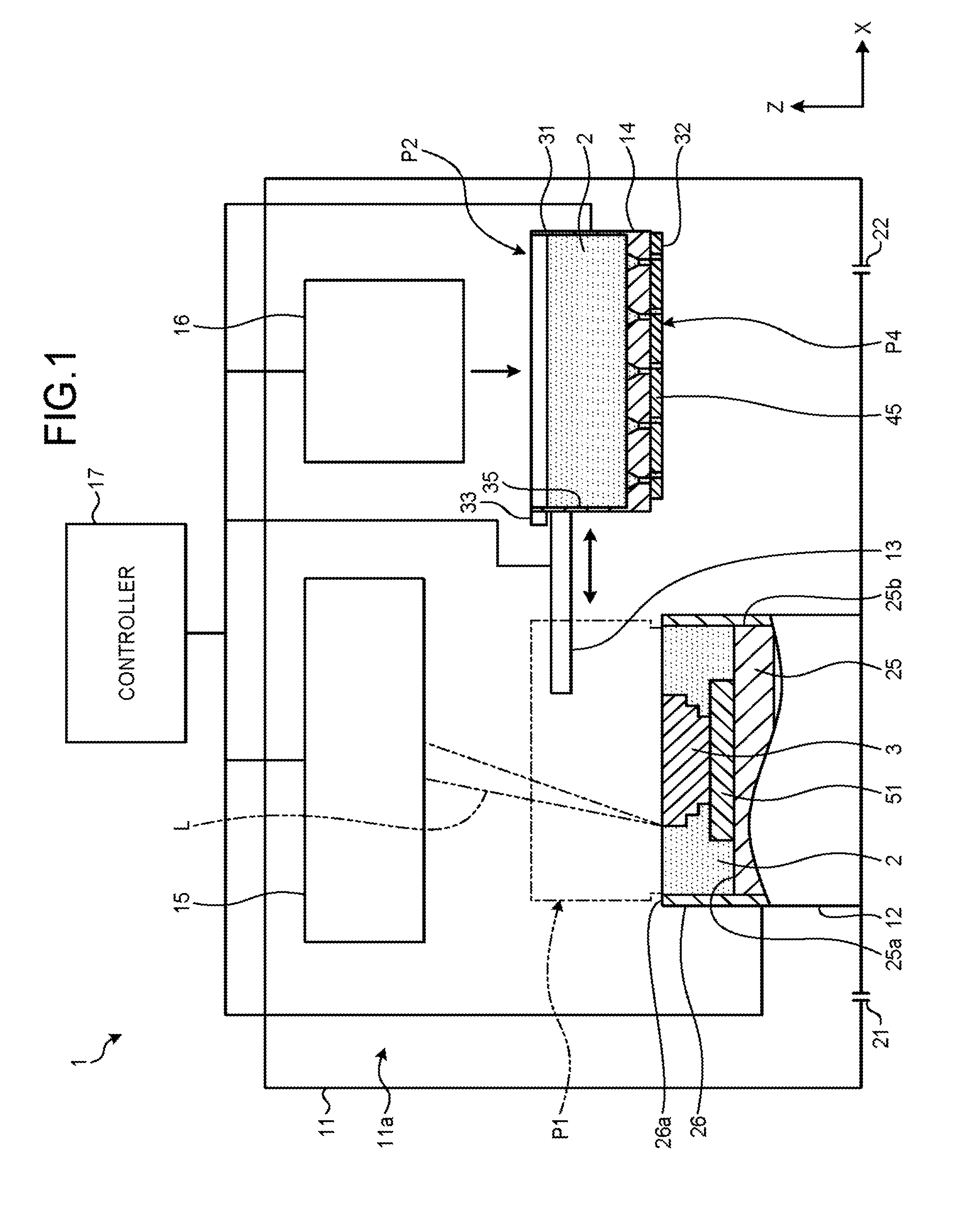
Embodiments of the present invention relate to material feeders of additive manufacturing apparatuses, additive manufacturing apparatuses, and additive manufacturing methods. There are known additive manufacturing apparatuses, such as three-dimensional printers. These three-dimensional printers form layers of a powdery material and solidify such a material for each layer of the material with binders (bonding agents) or laser beams to form three-dimensional shapes. Patent Literature 1: Japanese Patent Application Laid-open No. 2007-216595 Reducing forming time of layers of a material results in the reduction of manufacturing time of a three-dimensional shape. An example of a problem addressed by the present invention is to provide a material feeder of an additive manufacturing apparatus, an additive manufacturing apparatus, and an additive manufacturing method that reduce feeding time of a powdery material. According to one embodiment, a material feeder includes a feeding unit. The feeding unit includes a container that is containable of a powdery material and a first wall that is provided with a plurality of first openings communicated with the container and at least partially covers a region to which the material is fed, the feeding unit feeding the material in the container from the first openings to the region to form a layer of the material. Hereinafter, a first embodiment will be described with reference to As illustrated in As illustrated in the drawings, an X-axis, a Y-axis, and a Z-axis are defined in the present specification. The X-axis, the Y-axis, and the Z-axis are orthogonal to each other. In the present specification, an X-axis direction, a Y-axis direction, and a Z-axis direction are respectively assumed as a width direction, a depth (length) direction, and a height direction of the material feeder 14. The treatment, tank 11 is formed into an enclosable box shape, for example. The treatment tank 11 has a treatment chamber 11 The treatment chamber 11 The stage 12 has a platform 25 and a circumferential wall 26. The platform 25 is a square plate-like shaped member, for example. The shape of the platform 25 is not limited to this example, and may foe a member having other shapes including another quadrangle (quadrilateral) including a rectangle, a polygon, a circle, and a geometry shape. The platform 25 has an upper face 25 The circumferential wall 26 extends in a direction along the Z-axis and is formed into a quadrangular tube shape surrounding the platform 25. Each of the four end faces 25 The platform 25 is movable within the circumferential wall 26 in the direction along the Z-axis with various devices, such as oil-pressure elevators. When the platform 25 moves uppermost, the upper face 25 The moving device 13 has a rail coupled to the material feeder 14, a conveyance arm, or other various devices, and translates the material feeder 14, for example. The moving device 13 moves the material feeder 14, for example, between a feed position P1 and a standby position P2. The feed position P1 is an example of the upside of a region. The standby position P2 is an example of a position that is off from the upside of the region. As illustrated in The tank 31 is formed into a substantially quadrangular box type. The tank 31 has an upper face 31 The tank 31 is provided with a container 35, a bottom wall 36, and a plurality of feed ports 37. The bottom wall 36 is an example of a first wall and may be also referred to as a lower part or a bottom part, for example. The feed ports 37 are an example of first openings, and may be also referred to as ejection ports, holes, or dropping parts, for example. The container 35 forms cuboid-shaped recessed part that is formed into a quadrangle-shaped in a plan view and that communicates with the upper face 31 The container 35 contains a powdery material 2. The opening part of the container 35 in the upper face 31 The bottom wall 36 is a quadrangular plate-shaped part that forms the lower face 31 The feed ports 37 are each provided in the bottom wall 36. The feed ports 37 have the substantially same shape each other. The feed ports 37 extend in the direction along the Z-axis and are each communicated with the container 35. The feed ports 37 each have a feed hole 41 and an introducing part 42. The introducing part 42 may be also referred to as a hopper, a funnel part, or a conical part, for example. Each feed hole 41 is a circular hole that communicates with the lower face 31 Each introducing part 42 forms a conical recessed part that communicates with the bottom face 35 As illustrated in The distance (pitch) between one feed port 37 and another one next, to the feed port 37 is, for example, 1 mm. The pitch between the feed ports 37 is not limited to this example. The opening part of one introducing part. 42 in the bottom, face 35 As illustrated in The closure wall 45 is a substantially Quadrangular plate-like shaped, member that covers the lower face 31 When the material feeder 14 is at the feed position P1, the lower face 45 The communicating holes 46 are each provided in the closure wall 45. Each communicating hole 46 is a circular hole provided from the upper face 45 The communicating holes 46 are arranged at a substantially uniform interval in the direction along the X-axis and the direction along the Y-axis, similarly to the feed ports 37. The distance (pitch) between one communicating hole 46 and another one next to the communicating hole 46 is 1 mm, for example, similarly to the interval of the feed ports 37. That is to say, the communicating holes 46 are arranged in the same direction as the feed ports 37 and at the same interval, as the feed ports 37. The closure wall 45 can move, for example, in the direction along the X-axis, with various devices including an actuator. The movement direction of the closure wall 45 is not limited to this example. The closure wall 45 moves between an opening position P3 and a closing position P1, for example. The opening position P3 is an example of a second position. The closing position P4 is an example of a first position. When the closure wall 45 is located at the opening-position P3, the communicating holes 46 each communicate with the feed holes 41 of the feed ports 37. That is to say, each feed hole 41 is opened by the corresponding communicating hole 46. As illustrated in When the feed, holes 41 are opened, the powdery material 2 contained in the container 35 falls by gravity from the feed ports 37 and communicating holes 46. The material 2 in the container 35 is led to the feed hole 41 via the sloped inner circumferential face of each, introducing part 42. The fall amount of powders per unit time is substantially constant regardless of the height of the material 2 contained in the container 35, similarly to hourglasses. The container 35 may be provided with a partitioning plate corresponding to each feed port 37. The partitioning plate partitions the material 2 contained in the container 35, and causes the material 2 to be uniformly led to the corresponding introducing part 42 of the feed port 37. The vibrator 33 is, for example, a motor that turns an eccentric weight. The vibrator 33 vibrates the material feeder 14. The vibration of the material feeder 14 facilitates the material 2 in the container 35 falling from the feed ports 37 and communicating holes 46. The optical device 15 illustrated in The optical device 15 is located above the stage 12. The optical device 15 may be placed at another place. The optical device 15 converts the laser beam L that the light source emits into a parallel beam with the conversion lens. The optical device 15 causes the laser beam L to reflect on the galvano mirror, which can change its tilt angle, and causes the laser beam L to converge with the converging lens, to irradiate the desired position with the laser beam L. The material replenishing device 16 can contain more material 2 than the container 35. The material replenishing device 16 is placed above the standby position P2 and has an openable and closable door. When the material feeder 14 is at the standby position P2, the door faces the container 35, which communicates with the upper face 31 When the material feeder 14 is located at the standby position P2, the material replenishing device 16 opens the door and feeds the material 2 to the container 35. When the material feeder 14 is not located at the standby position P2, the material replenishing device 16 closes the door to prevent the material 2 from falling. The controller 17 is electrically connected, to the stage 12, the moving device 13, the material feeder 14, the optical device 15, and the material replenishing device 16. For example, the controller 17 has various electronic components, such as a CPU, a ROM, and a RAM. The controller 17 reads and executes a program stored in the ROM or other storage devices to control the stage 12, the moving device 13, the material feeder 14, the optical device 15, and the material replenishing device 16. The three-dimensional printer 1 forms the manufactured object 3 based on the control (program) of the controller 19. Hereinafter, it will be described that an example of a procedure in which the three-dimensional printer 1 forms the manufactured object 3 from the powdery material 2. A method in which the three-dimensional printer 1 forms the manufactured object 3 is not limited to the description below. First, three-dimensional shape data of the manufactured object 3 is input to the controller 17 of the three-dimensional printer 1, for example, from an external personal computer. The three-dimensional shape data is data for CAD, for example, but is not limited to this example. Next, the material replenishing device 16 feeds the material 2 to the container 35 of the material feeder 14 at the standby position P2. The controller 17 weighs the material 2 contained in the container 35 with a sensor, for example, and forces the material replenishing device 16 to feed the material 2 to the container 35 until the weight reaches a certain value. As a result, the container 35 contains a certain amount of the material 2. When the container 35 has already contained a certain amount of the material 2, feeding the material 2 from the material replenishing device 16 may be omitted. The closure wall 45 of the material feeder 14 is usually located at the closing position P4. Thus, the feed port 37 is closed by the closure wall 45, and it is prevented that the material 2 contained in the container 35 falls from the feed ports 37. Then, the moving device 13 moves the material feeder 14 from the standby position P2 to the feed position P1. When arriving at the feed position P1, the material feeder 14 feeds the material 2 onto the stage 12 as follows. As illustrated in The base 51 is a quadrangular plate-like shaped member, for example. The shape of the base 51 is not limited to this example, and is determined depending on the shape of the manufactured object 3. The base 51 has a flat upper face 51 First, the platform 25 of the stage 12 is placed so that the distance between the upper face 51 The material 2 is spread all over around the base 51 in advance. A surface 2 The surface 2 The feed region R is a substantially flat, quadrangular face of 250 mm×250 mm, similarly to the upper face 25 The bottom wall 36 of the material feeder 14 at the feed position P1 is located above the feed region R. The bottom wall 36 covers the entirety of the feed region R. The bottom wall 36 may partially cover the feed region. R. The lower face 31 When the material feeder 14 arrives at the feed position P1, the controller 17 causes the closure wall 45 to move to the opening position P3. This causes the communicating holes 46 of the shutter 32 to be communicated with the corresponding feed holes 41 of the feed, ports 37, and causes the feed ports 37 to be opened. The material feeder 14 is vibrated by the vibrator 33. As a result, through the feed ports 37 and the communicating holes 46, the material 2 in the container 35 falls onto the feed region R. The material feeder 14 feeds the material 2 to the feed region R from the feed ports 37 in parallel. The first material feeder 14 may not have the vibrator 34. If there were no vibration caused by the vibrator 34, a first material 3 falls by gravity from the feed ports 37 and communicating holes 46. As illustrated in The areas of the divided sections RD are equal to each other. The divided sections RD are each arranged in the direction along the X-axis and the direction along the Y-axis. The feed ports 37 and communicating holes 46 face the corresponding divided sections RD. That is to say, each feed port 37 and communicating hole 46 is located above the corresponding divided section RD, and oppose (face) the divided section RD. The feed ports 37 and communicating holes 46 each feed the material 2 to the corresponding divided sections RD. While the material 2 is fed to the feed region R from the feed ports 37 and communicating holes 46, the material feeder 14 is moved, for example, by the moving device 13, in the direction along the X-axis and the direction along the Y-axis, as indicated by the arrow in The material 2 is fed to each divided section RD, so that the feed region R is filled with a layer of the material fed to the divided section RD and a continuous layers ML2 of the material 2 is formed, throughout the entirety of the feed, region R. In other words, the layer ML2 of the material 2 is placed on the layer ML1. The amount of the material 2 fed to each divided section RD is substantially equal. Thus, the thickness of the layer ML2 formed in the feed region R is substantially equal regardless of its position. When the layer ML2 Is formed in the feed region R, the surface 2 The controller 17 counts, for example, with a timer, an elapsed time after the closure wall 45 moves to the opening position P3 and the feed ports 37 are opened. When a certain time has elapsed after the feed ports 37 being opened, the controller 17 causes the closure wall 45 to move from the opening position P3 to the closing position P4 and causes the closure wall 45 to close the feed ports 37. The fall speed of powders that, pass each feed port 37 is substantially constant, and thus the fall amount thereof can be controlled with times for which the feed ports 37 are opened. The lower face 45 When the layer ML2 of the material 2 is formed in the feed region R as above, the moving device 13 moves the material feeder 14 from the feed position P1 to the standby position P2. As the material feeder 14 moves from the feed position P1 to the standby position P2, the lower face 45 Next, as illustrated in In the layer ML2 of the material 2, the part irradiated with the laser beam L melts. In other words, the material 2 is irradiated with the laser beam L to be solidified after being partially melted. As a result, a part (one layer) of the manufactured object 3 is formed in the layer ML2 of the material 2. The material 2 may be sintered. While the layer ML2 of material 2 is irradiated with the laser beam L, the material replenishing device 16 feeds the material 2 to the container 35 of the material feeder 14. The volume of the material 2 contained in the container 35 is larger than the volume of the layer ML2 of the material 2 formed in the feed region R. When the optical device 15 finishes irradiating the material 2 of the layer ML2 with the laser beam L, the platform 25 moves downward, for example, by 50 μm. The distance by which the platform 25 moves is equal to the thickness of the layer ML2. As a result, the distance between the surface 2 The surface 2 The optical device 15 partially melts the material 2 of the layers ML2, ML3, ML4, . . . , and forms a part of the manufactured object 3, each time the layers ML2, ML3, ML4, . . . are formed. The three-dimensional printer 1 repeats the formation of the layers ML2, ML3, ML4, . . . of the material 2 caused by the material feeder 14 and the fusion of the material 2 caused by the optical device 15 to form the three-dimensionally shaped manufactured object 3. The manufactured object 3, which is formed within the treatment tank 11, is taken out of the treatment chamber 11 In the three-dimensional printer 1 according to the first embodiment, the material feeder 14 feeds the material 2 from the feed ports 37 provided in the bottom wall 36 to the feed region R in parallel to form the layer ML2, ML3, ML4, . . . of the material 2 in (to place the material 2 on) the feed region R. This shortens the distance by which the material feeder 14 moves above the feed region R to form the layer ML2, ML3, ML4, . . . of the material 2 in the feed region R and reduces forming time of the layers ML2, ML3, ML4, . . . of the material 2 in the feed region R. Furthermore, providing the feed port 37 in number corresponding to the size of the feed, region R causes the forming time of the layers ML2, ML3, ML4, . . . of the material 2 in the feed region R to be constant regardless of the size of the feed region R. For example, for the size of the feed region R of 1000 mm×0.1000 mm, if the number of feed ports 37 per unit, area is the same as the present, embodiment, the forming time of the layers ML2, ML3, ML4, . . . of the material 2 is the same as the present, embodiment. The material 2 falls by gravity from the feed ports 37, so that the material 2 is fed to the feed region R. This simplifies the structure of the material feeder 14 and reduces the forming time of the layers ML2, ML3, ML4, . . . of the material 2 in the feed region R. Furthermore, for powders, their fall speed is substantially constant regardless of the height of the material 2 in the container 35, similarly to hourglasses. Thus, the feed amount is relatively easily controlled using the opening time of the feed ports 37. The feed ports 37 are placed in the bottom wall 36 in the form of grid point. This equalizes the distance between the positions (the fall spots S) to which the material 2 is fed and reduces the variation of the amount of the material 2 in the feed region R. The shutter 32 opens and closes the feed ports 37. Thus, when the material feeder 14 is at a position off from the feed region R, such as the standby position P2, the exit of the material 2 from the feed ports 37 is suppressed. Furthermore, the configuration that suppresses the material from leaking is implemented in a relatively simple configuration. At the closing position P4, the closure wall 45 closes the feed ports 37. When the closure wall 45 is at the opening position P3, the communicating holes 46 each communicate with the feed ports 37, and the feed ports 37 are opened. This causes the feed port 37 to be opened and closed easily. The vibrator 33 vibrates the material feeder 14 to facilitate the material 2 falling from the feed ports 37 to the feed region R. As a result, the material is evenly fed from the feed ports 37. The material feeder 14, in which the feed ports 37 each feed the material 2 to the corresponding divided sections RD, forms the continuous layers ML2, ML3, ML4, . . . of the material 2 in the feed region R. This shortens the distance by which the material feeder 14 moves above the feed region R to within the extent of the divided section RD, and reduces the forming time of the layers ML2, ML3, ML4, . . . of the material 2 in the feed region R. In other words, the layers ML2, ML3, ML4, . . . are formed by feeding the material to each divided section RD in parallel. Thus, the material 2 is fed to a wider range in relatively short time, and the variation of the amount and thickness of the material 2 depending on its position is reduced. Furthermore, each feed port 37 feeds the material 2 to the corresponding divided section RD, to form the layers ML2, ML3, ML4, . . . of the material 2 in the feed region R. This causes the forming time of the layers ML2, ML3, ML4, . . . of the material 2 in the feed region R to be constant regardless of the size of the feed region R. The material feeder 14 moves sac that the fall spots S of the material 2 move within the divided sections RD. As a result, the material 2 is fed to each of the divided sections RD thoroughly, and the material 2 is evenly fed to the feed region R. If the size of the feed hole 41 and the size of the material 2 are constant, the amount by which the powdery material 2 falls from the feed port 37 is determined depending on time. The controller 17 controls the opening time of the feed ports 37 with the shutter 32, and closes the feed ports 37 when a certain time has elapsed after the feed ports 37 being opened. This causes the amount of the material 2 fed to the feed region R to be constant. The closure wall 45 moves from the opening position P3 to the closing position P4 to level the layers ML2, ML3, ML4, . . . of the material 2 formed in the feed region R. As a result, the surface 2 The material replenishing device 16 feeds the material 2 to the container 35 of the material feeder 14 at the standby position P2. As a result, the material 2 is fed to the container 35 while the layers ML2, ML3, ML4, . . . of the material 2 is melted by the optical device 15, and the manufactured object 3 is effectively formed. Hereinafter, a second embodiment will be described with reference to The first slits 61 are each provided in the bottom wall 36. The first slits 61 are provided from the lower face 31 The shutter 32 of the second embodiment has a plurality of closure plates 64 instead of the closure wall 45. Each closure plate 64 is an example of a second wall. The closure plates 64 extend in the direction along the Y-axis. The closure plates 64 are arranged at a substantially uniform interval in the direction along the X-axis. The width (the dimension in the direction along the X-axis) of each closure plate 64 is either substantially equal to or larger than the width of the first slit 61. One end in the direction along the X-axis of each closure plate 64 is provided with a knife edge 64 Second slits 65 are each provided between the closure plates 64. The second slits 65 extend in the direction along the Y-axis. The second slits 65 are arranged at a substantially uniform interval in the direction along the X-axis. As illustrated in As illustrated in As illustrated in As indicated by an arrow in As illustrated in The closure plates 64 move from the opening position P3 to the closing position P4 to close the first slits 61 and to slide on the surface 2 In the three-dimensional printer 1 of the second embodiment, the material feeder 14 feeds the material 2 to the feed region R from the first slits 61 in parallel. In this manner, the first opening is not limited the feed port 37 of the first embodiment and the first slit 61 of the second embodiment, and is formed into various shapes. Hereinafter, a third embodiment will be described with reference to The obstructing part 71 has a plurality of pistons 72 and a supporting member 73. Each piston 72 is an example of a valve member and may be also referred to as a structure, an extrusion part, a pressurization part, an insertion part, or a plug, for example. The supporting member 73 may be also referred to as a coupling unit or a moving unit. Each piston 72 is formed into a rod shape that extends in the direction along the Z-axis. One end of the piston 72 is provided with a valve part 72 The pistons 72 are placed in the container 35 so that the valve parts 72 The supporting member 73 supports the pistons 72. The pistons 72, which are supported by the supporting member 73, are arranged at a substantially uniform interval in the direction along the X-axis and the direction along the Y-axis. That is to say, the pistons 72 are arranged in the same manner as the feed ports 37 and at the same interval as the feed ports 37. The supporting member 73 can move the pistons 72 in the direction along the Z-axis, with various devices including an actuator. In other words, the supporting member 73 moves the pistons 72, which is provided with the valve parts 72 As illustrated in As illustrated in As illustrated in The pistons 72 moved to the opening position P5 gradually moves towards the closing position P6. The valve part 72 When a certain time elapses after the movement of the pistons 72 to the opening position P5, the pistons 72, which move towards the closing position P6, arrive at the closing position P6. The material 2 in the feed holes 41 is extruded from the feed holes 41 by the valve parts 72 As illustrated in In the three-dimensional printer 1 of the third embodiment, the pistons 72 at the closing position P6 fit into the feed ports 37 to close the feed ports 37. This causes the feed ports 37 to be opened and closed easily. The pistons 72 move from the opening position P5 to the closing position P6, to each extrude the material 2 in the container 35 into the feed ports 37 and fit into the feed ports 37 to close the feed ports 37. This further reduces the feeding time of the material 2 to the feed region R, and causes the amount of the material 2 to be constant more easily. Hereinafter, a fourth embodiment will be described with reference to The air supplying device 81 is an air compressor, for example. The air supplying device 81 is communicated with the material feeder 14 through a plurality of tubes 82. Each tube 82 is formed of a flexible synthetic resin, for example. The tank 31 of the material feeder 14 is provided with a plurality of air supply paths 84. One end of each air supply path 84 is communicated with the tube 82. The other end of the air supply path 84 communicates with the lower face 31 The closure wall 45 of the shutter 32 is provided with a plurality of blow ports 86. Each blow port 86 is a hole provided from the upper face 45 In the three-dimensional printer 1 of the fourth embodiment described above, the platform 25 is lowered so that the distance between the feed region R and the lower face 45 The material feeder 14 at the feed position P1 moves the closure wall 45 to the opening position P3 to open the feed ports 37. As a result, the material feeder 14 feeds the material 2 to the feed region R from the feed ports 37 in parallel. When a certain time elapses after the movement of the closure wall 45 to the opening position P3, the controller 17 moves the closure wall 45 to the closing position P4. This causes the feed ports 37 to be closed by the closure wall 45. The distance between the surface 2 The closure wall 45 moves to the closing position P4, so that the air supply paths 84 are opened by the blow ports 86. The air supplying device 81 sends air (blows air) into a space surround by the circumferential wall 26 and the closure wall 45 through the tubes 82, the air supply paths 84, and the blow ports 86. When a certain time elapses after the initiation of sending air, the air supplying device 81 stops the blow. As a result, the material 2 that flies in the air falls to the feed region R. The fallen material 2 forms the substantially uniform layers ML2, ML3, ML4, . . . in the feed region R. In the present embodiment, the material 2 is stirred by the air supplying device 81, but the material 2 may be stirred by other means, such as brushes. In the three-dimensional printer 1 of the fourth embodiment, the air supplying device 81 sends air to the space surrounded by the closure wall 45 and the circumferential wall 26 to raise the material 2 fed to the feed region R. The raised material 2 falls to the feed region R to form the layers ML2, ML3, ML4, . . . , which have a substantially uniform thickness. As a result, the surface 2 Hereinafter, a fifth embodiment will be described with reference to The internal shutter 91 is placed on the bottom face 35 The upper closure wall 92 is a substantially quadrangular plate-like member that covers the bottom face 35 The upper communicating holes 93 are each provided in the upper closure wall 92. Each upper communicating hole 93 is a circular hole provided from the upper face 92 The upper communicating holes 93 are arranged at a substantially uniform interval in the direction along the X-axis and the direction along the Y-axis, similarly to the feed ports 37. The distance (pitch) between one upper communicating hole 93 and another one next to the upper communicating hole 93 is 1 mm, for example, similarly to the interval of the feed ports 37. That is to say, the upper communicating holes 93 are arranged in the same manner as the feed ports 37 and at the same interval as the feed ports 37. The upper closure wall 92 can move, for example, in the direction along the X-axis, with various devices including an actuator. The movement direction of the upper closure wall 92 is not limited to this example. The upper closure wall 92 moves between an opening position P7 and a closing position P8, for example. When the upper closure wall 92 is located at the closing position P8, the positions of the upper communicating holes 93 are shifted from the corresponding introducing parts 42 of the feed ports 37. Thus, the upper closure wall 92 at the closing position P8 closes the introducing parts 42 of the feed ports 37. The material feeder 14 of the fifth embodiment described above moves the upper closure wall 92 to the opening position P7 when the closure wall 45 is at the closing position P4. As a result, the feed ports 37 are each filled with the material 2 in the container 35. The material 2 with which the feed ports 37 are filled is supported by the closure wall 45 at the closing position P4. The volume of each feed port 37 is equal to the volume of the corresponding divided section RD to which the feed port 37 supplies the material 2. When the feed ports 37 has been filled with the material 2, the upper closure wall 92 is moved to the closing position P8. As a result, in each feed port 37, the material 2 fed to the corresponding divided section RD in a formation of one of the layers ML2, ML3, ML4, . . . of the material 2 is held. The material feeder 14 at the feed position P1 moves the closure wall 45 to the opening position P3. As a result, the feed ports 37 are opened and the material 2 held in each feed port 37 is fed from each feed port 37 to the feed region R. At this time, the upper closure wall 92 prevents the material 2 contained in the container 35 from flowing into the feed ports 37. Each feed port 37 feeds the holding material 2 to the corresponding divided section RD, so that the layers ML2, ML3, ML4, . . . of the material 2 is formed in the feed region R and each feed port 37 empties. In the three-dimensional printer 1 of the fifth embodiment, each feed port 37 holds a certain amount of the material 2. This causes the amount of the material 2 fed to the feed region R to be constant. According to at least one embodiment described above, a feeding unit feeds a material from a plurality of first openings provided in a first wall to a region in parallel to form a layer of the material in the region. This shortens the distance by which the feeding unit moves above the region, and reduces feeding time of the powdery material. While certain embodiments have been described, these embodiments have been presented by way of example only, and are not intended to limit the scope of the inventions. Indeed, the novel embodiments described herein may be embodied in a variety of other forms; furthermore, various omissions, substitutions and changes in a the form of the embodiments described herein may be made without departing from the spirit of the inventions. The accompanying claims and their equivalents are intended to cover such forms or modifications as would fall within the scope and spirit of the inventions. For example, in the above embodiments, the three-dimensional printer 1 melts the material 2 with the laser beam L to form the manufactured object 3. However, the three-dimensional printer 1 is not limited to this example, and may feed, for example, a bonding agent (a binder) to the material 2 with an ink jet and other devices, to solidify the material 2 partially to form the manufactured object 3. In this case, the material 2 is not limited to a metal, and may be other materials, such as a resin. Furthermore, in the above embodiment, the three-dimensional printer 1 uses the laser beam L as an energy ray for melting the material 2. However, an energy ray may be, as far as melting the material similarly to the laser beam L, for example, an electron beam and an electromagnetic wave from a microwave region to an ultraviolet region. According to one embodiment, a material feeder includes a feeding unit. The feeding unit includes a container that is containable of a powdery material and a first wall that is provided with a plurality of first openings communicated with the container and at least partially covers a region to which the material is fed, the feeding unit feeding the material in the container from the first openings to the region to form a layer of the material. 1: A material feeder of an additive manufacturing apparatus, the material feeder comprising:
a feeding unit comprising a container that is containable of a powdery material, and a first wall that is provided with a plurality of first openings configured to be communicated with the container and is configured to at least partially cover a region to which the material is fed, the feeding unit configured to feed the material in the container from the first openings to the region and configured to level the material to form a layer of the material. 2: The material feeder of an additive manufacturing apparatus according to 3: The material feeder of an additive manufacturing apparatus according to 4: The material feeder of an additive manufacturing apparatus according to 5: The material feeder of an additive manufacturing apparatus according to 6: The material feeder of an additive manufacturing apparatus according to 7: The material feeder of an additive manufacturing apparatus according to 8: The material feeder of an additive manufacturing apparatus according to 9: The material feeder of an additive manufacturing apparatus according to 10-11. (canceled) 12: An additive manufacturing apparatus comprising:
a feeding unit comprising a container that is containable of a powdery material, and a first wall that is provided with a plurality of first openings configured to be communicated with the container and is configured to at least partially cover a region to which the material is fed, the feeding unit configured to feed the material in the container from the first openings to the region and configured to level the to form a layer of the material; a moving unit configured to change a relative position of the feeding unit to the region; and a forming unit configured to partially solidify the material fed to the region by the feeding unit. 13: The additive manufacturing apparatus according to the first openings are placed in a form of grid points, and the feeding unit is configured to feed the material from each of the first openings to a section in the region to form the layer of the material, the layer being continuous. 14: The additive manufacturing apparatus according to 15: The additive manufacturing apparatus according to the feeding unit further comprises an opening-closing part configured to open and close the first openings, and the controller configured to control opening time in which the first openings are opened by the opening-closing part. 16: The additive manufacturing apparatus according to the opening-closing part comprises a second wall that is configured to oppose the region, that is provided with a plurality of second openings, and that is movable along the first wall between a first position in which the second wall closes the first openings and a second position in which the first openings communicate with the respective second openings, and the second wall is configured to level the layer of the material formed in the region when moving from the first position to the second position. 17: The additive manufacturing apparatus according to the moving unit is able to locate the feeding unit at an upside of the region and a position that is off from the upside of the region, and the replenishing unit is configured to feed the material to the container of the feeding unit located at the position that is off from the upside of the region. 18: The additive manufacturing apparatus according to a circumferential wall configured to surround the region; and a blowing part, wherein the feeding unit is configured to block an opened end of the circumferential wall and to be separated from the material fed to the region, and the blowing part is configured to blow air into a space surrounded by the feeding unit and the circumferential wall to raise the material fed to the region. 19-21. (canceled) 22: An additive manufacturing method comprising:
opening a plurality of openings provided in a wall that covers a region to feed a powdery material from the openings to the region; closing the openings when a certain time has elapsed after the opening of the openings to form a layer of the material on the region, and leveling a surface of the layer of the material with a feeding unit that comprises the wall. 23-24. (canceled) 25: The additive manufacturing method according to FIELD
BACKGROUND
CITATION LIST
Patent Literature
SUMMARY OF THE INVENTION
Problem to be Solved by the Invention
Means for Solving Problem
BRIEF DESCRIPTION OF DRAWINGS
DETAILED DESCRIPTION